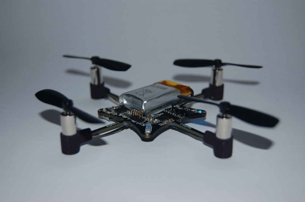
One of the ideas with the Crazyflie was to make a simple flying platform and what’s simpler than just attaching the motors directly to the PCB? On our first prototypes we used hot-glue to attach the motors which work out pretty well. The problem was that when you crashed the motors often came loose, and in some cases, so did the wires attached to the motors. Reparing this turned out to be pretty teadious and it makes flying it a lot less fun, since the iteration time for trying new things becomes longer. We did a few tests with different protections, like soldering a ring of piano-wire, but when we decided to make a kit out of the Crazyflie we realized that we needed something that was easier to manufacture.
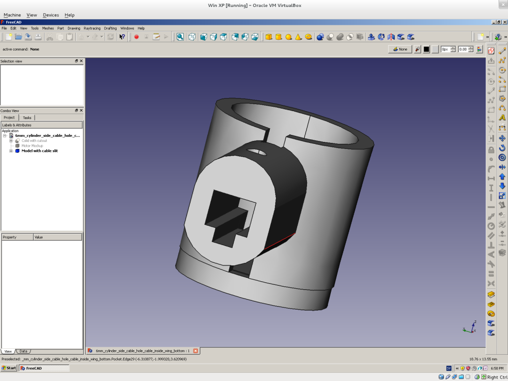
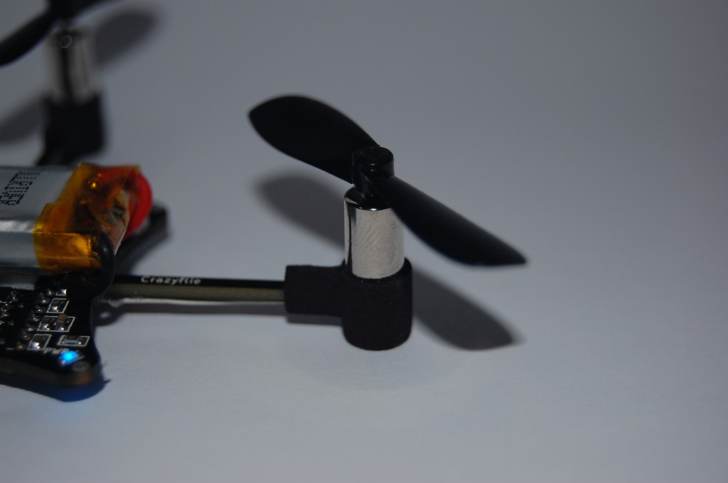
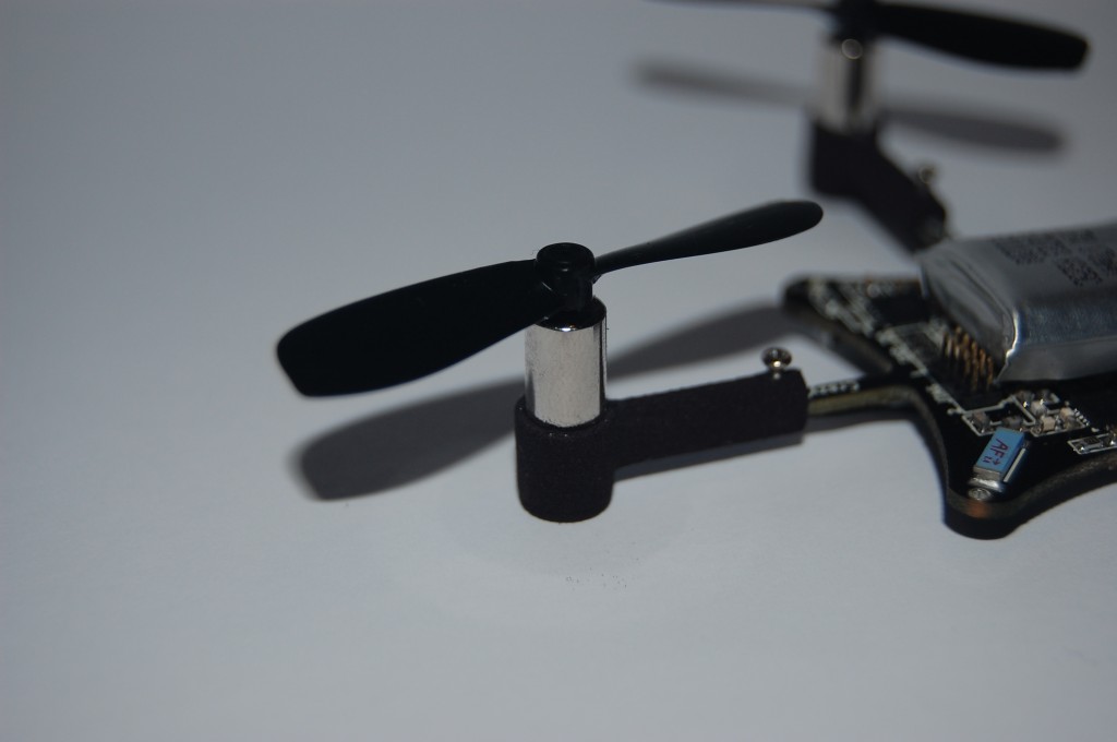
Since we could not find any off-the-shelf motor mounts we decided to make our own. Our idea is to place the motor in the mount and the mount on the wing. We have tried a few different solutions but the current leading design is one where we feed the cable from the mount out under the wing and to the soldering point for the wire. We have also made a telescopic version so it is possible to adjust the arm length for adjustable flight dynamics or to attach bigger propellers. After some more testing we will decide which one we will go for.
The CAD work is done in an open-source CAD tool named FreeCAD. After struggling for a while with an unstable versions, the 0.12 branch finally became very stable. The images below is the second iteration of prototypes that we have done using Shapeways. It’s is a 3D printing house in the Netherlands that has a great service where you upload models, choose what material you want them printed in, and then two weeks later you receive them in the mail! The durability is pretty good as well. We have only managed to break one, and that’s after a lot of violent crashes and a more fragile design.


I can’t wait to order one of these :) I wonder though, will the battery life be only 7 minutes still? Also I note you use the PC to control it, does the hardware that sends the radio signal to the quadcopter come with it or will it be a separate purchase?
One more question.. is it going to be hackable? I’d love to turn it into an autonomous quad later :D
will 3d printer owners be able to produce their own motormounts?
@njssjhhsh
Well if you want to print some mounts we will not stop you :-), but it might be though meeting the same precision, so the CAD certainly have to modified. Our plan is to evetually plastic mould the mounts, but it all comes down to cost. We have to make many mounts/crazyflies for a mould to be cost efficient.
@Don
Yes, the battery life will still be around 7 min. It is possible to change to a bigger battery but that adds weight which makes the motor less efficient and we think our current setup is a good trade-off. And yes, the idea is that it should be hackable. The tricky thing is to make the addons small enough.
Jag tror ni är fel ute med 3D-utskriven plast..
Tänk på gamla telefoner från Nokia och Ericson – de var designade att falla isär när man tappade dem, och det var det som tog upp kraften så inte något gick sönder. Vore det inte smartare att använda en stiftlist eller liten “molex”-kontakt? Då skulle det gå lätt att montera ner också så ni får mindre paket att skicka. Dessutom kan det bli så motorn håller fast för flygning men om man kraschar åker den av, som på de gamla telefonerna.
3D-plast är skört och dyrt imho.
Ser fram emot att kunna beställa denna – ni borde lägga upp en kickstarter-sida ;)
I’ll write the answer in english, hope you don’t mind.
I agree with that 3D-printed plastic is not as durable as a molded one but it all comes down to cost. It might be that we make a pre-series for developers with printed parts and make a mold after that.
As you are pointing out breaking apart at a crash isn’t always something bad since the breaking absorb energy. However it is also important that things are attached firmly otherwise the motor vibrations are enhanced and it doesn’t fly that well anymore. It’s a tricky thing to get right…
Awesome. I imagine the motors could be upgraded to carry more weight etc the more it gets tinkered with depending upon a person’s needs. Simply cannot wait for this :)
SoooO awesome!!! Can’t wait !!! Any time frame when it be available to pepurchase ?:)
Would you say at this point that the board revision is final and the electronic hardware (motors not included) are ‘set in stone’?
@Yugi
We are aiming to have it ready not later than the first half of 2012. We hope it will be ready soon and that we can keep our estimation.
@Don
Yes, the electronics is pretty much finished but we are doing some final fixes. The Micro-b-usb connector we use is a bit week and there are the issues mentioned in one of the posts.
will it be sold RTF or do you have to do the assembly of the ciurcut by yourself? And what contry are you from? sweden?
What propellers do you use? Where can they be bought?
Awesome work.
we are currently working on a microcopter like this. we are using Atmega328 controller and got stuck with the motor driver system. which motor drivers are you using? we want to try it with pager motors, Do you think that is a good idea?
We use coreless brushed pager/toy motors 6x15mm but they come in many different sizes. Our motors can at best genereate 7-10 gram of thrust with our propellers (Silverlit X-Twin size). Selecting the right motor/prop combo is important and at the micro quad sizes there are not that many alternatives to choose from.