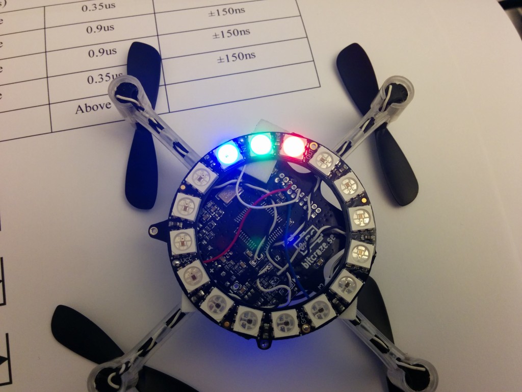
A couple of weeks ago we found the NeoPixel ring from Adafruit at a local shop, we had to attach this neat board to our copter and see what cool effect we could make with it. The ring has 16 RGB LEDs that can be driven independently with only one data wire. The LEDs the Neopixel contains are called WS2812.
This post is describing the development of a WS2812 driver for the Crazyflie. A later post will show the usage we did of it (fairly limited in comparison of the seemingly endless possibility, as usual we have more ideas than time to execute them :-).
The WS2812 LED
First of all we needed to see how to control the LEDs. The protocol used by the WS2812 is quite simple but special. All LED on the ring have a data input and a data output pin in a chained manner. Colors of the LED is send over the Data line to the first LED that will save it internally. When sending a second color the first LED will send the saved color to the second LED. And so on, by sending 16 color data we can set the color of all LEDs of the ring independently. Colors are sent as 24 bits (8 bits per component).
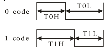
Up to there nothing is really peculiar, the system is pretty neat and allows to control a lot of LEDs with just one IO. The problems comes with the Bit encoding:
Bits are encoded with pulse width: a short pulse means 0 and a long pulse means 1. The bitrate is of about 800KHz and the tolerances on bit timing is pretty tight. As there is no hardware peripheral dedicated for this (on common microcontrollers), this bitstream needs to be implemented either by bit-banging or by being a bit creative with the peripheral we actually have at our disposal.
Driver implementation
Adafruit did implement a driver for the WS2812 for Arduino, this is a software implementation that uses the CPU to implement the signal. However at that bitrate a software/bit-bang implementation have to be timed carefully and the easiest for that is actually to implement it in assembler. Arduino runs on an AVR processor and these processor are very predictable: each instruction runs in a specified number of clock cycle which makes it possible to implement a timed loop like the one of Adafruit. However this becomes impractical on bigger CPU that implements caches and other optimization that makes it really hard to predict how much cycle each instruction will take.
The Crazyflie runs a STM32F103 based on an ARM Cortex-M3. This is just complex enough to make the ASM-timed loop impractical: The CPU core runs at 72MHz but the flash is slower so a simple cache memory is inserted in the middle and depending of the state of this cache it may take from 1 to 3 cycles to execute an instruction. There is an even bigger problem: a CPU timed loop requires to stop all interrupt and to have the CPU running exclusively on updating the WS2812. We cannot allow that on the Crazyflie that require a 250Hz control loop to stay (controllably) airborne.
We asked Google to see if someone already came with a solution and actually someone did. The Elia’s Electronics Blog posted a neat, well documented, solution using the STM32 Pulse Width Modulation (PWM) capabilities of the STM32 to generate signals that the WS2812 understands. All we needed was a timer/pwm output then. It happens that we have one timer1 output on the Crazyflie extension port:
This is only 3 wires: VCOM for the battery voltage, GND and the timer output.
I started porting the Elia’s code to the Crazyfle. The only free timer we could easily use was different and much more complex than the one Elia uses. So part of the frustrating implementation was to figure out WHY the signal was looking weird on the scope! Finally after an hour or so the code was working:
Enhancements
Now that was not quite enough. The driver is using the PWM to generate the 1’s and 0’s pulse width and the DMA is used to feed the bit width independently of the CPU (so that it can do something else, like controlling the copter attitude…). It requires all the 16 LEDs data to be written in the memory buffer before starting the DMA. Each LED has 24 bits color data and each bit will be encoded as 16bit pulse length for the timer. It means that the full ring will take 768Bytes in RAM. It sounds small but its a bit too much for us and, most importantly, it does not scale: if we want a second ring the ram requirement will double.
To fix this I implemented two things: An easy one is that the DMA can do some type conversion and one of these is that it can read 8 bit in memory and write 16 bit in the peripheral. This allows to store only 8 bits pulse width in memory and so divides by 2 the memory requirement, but it still doesn’t scale.
The fix to scaling is double buffering. The STM32F103 does not implement DMA double buffering as such but what it has is close enough: circular DMA with half-transfer interrupt. The idea is to load the 2 first LED in a buffer and to start the DMA for 42 bytes in circular mode. When the DMA has transferred the first LED it triggers the half-transfers interrupt which allows the CPU to replace the first LED data by the 3rd. When the 2nd LED is transferred the transfer-complete interrupt is triggered by the DMA and the CPU fills in the 4th LED in place of the 2nd one. The DMA roll-over at the beginning of the buffer and sends what is now the 3rd LED data. This continues until all the LEDs has been sent. This solution scales: it requires a 42 bytes buffer for as many LED as we want!
Conclusion
All that process was not really simple. However the result is simple, now the only thing required to control a Neopixel ring in the Crazyflie is:
#define BLACK {0x00, 0x00, 0x00}</span>
static uint8_t color[][3] = {{40, 40, 40}, {32, 32, 32}, {16,16,16}, {8,8,8},
                             {4,4,4}, {2,2,2}, {1,1,1}, BLACK,
                             BLACK, BLACK, BLACK, BLACK,
                             BLACK, BLACK, BLACK, BLACK,
                            };

/* ... */
ws2812Send(color, 16);
And it will run nicely without interrupting other tasks like control and communication. Replace 16 by 32 to control 2 Neopixel rings. The current implementation has been pushed in the crazyflie-firmware neopixel_dev branch (still require some clean-ups!). Actual implementation is in ws2812.c and neopixelring.c.
The only problem left is not software: At the end of the battery life, the voltage is not enough to fully lit the blue LED. That make all white look orange-ish. The only way to fix this problem would be to step-up the battery voltage higher then the forward voltage of the blue LED. Though it works well enough without that.
Stay tuned for a following post about actual usage of the ring.


I got the firmware compiled and loaded, the parameters show up in the client. I also tested out the Neopixel ring with an Arduino first. But after connecting up the ring as it appears in your photo I’m not seeing anything after setting the pattern parameter. But the crazyflie certainly doesn’t like the extra weight.
Maybe I’ll wait until you bake it a little more then try to follow along again :-)
I completed this mod! Works great for me and looks ultra cool (not as cool as Crazyflie 2.0 with the LED expansion board though). To mitigate the weight problem I used Adafruit’s 12x LED ring instead of the 16x ring. You can read all about it on my Crazyflie blog.
Thank you for excellent work!
But you should check transmission complete flag (so, condition will be like ‘DMA_ISR_bit.TCIF2 && current_led >= total_led+1’) at end of ISR function before disabling timer, or it will disable timer at half-transfer condition (if you will use LED_PER_HALF to make batch transfers). This can leave data line in high state between data packets, and break reset state of WS2812.