Year: 2014

We are always looking for fun things to hack together using the Crazyflie. The last couple of weeks we contributed to two exciting open hardware campaigns on Indiegogo that we are hoping to get our hands on soon.

The VoCore

First up is the VoCore, a coin-sized SoC breakout with WiFi running Linux. Based on the RT5350, it could be used for WiFi control (with AP support) or to add extra power for doing calculations.

The second one is the 3Dpad, an open source gesture controller. We have been using the Leap Motion for flying before, and we are really eager to try the concept but with an open source project. Even tough the 3Dpad doesn’t support the same hand/finger tracking as the Leap Motion, we are hoping that we can hack together a usable controller for the Crazyflie. It uses capacitive technology that makes it possible to place it behind materials that are not transparent. Imagine placing it under the desk and flying with your hand above the desk!

Best of luck to the projects with financing and development!

This week we were planning on recording some FPV videos around the office with a new transmitter that gives us better range. But after battling with our USB capture device for a while we finally gave up. We will have to try to find a better one (that hopefully works in Linux!). But until then here’s two videos. First one from BBC is about the exciting future for flying robots (thanks to phenoptix for tipping us off to this one) and the second one is the recording from our presentation at Devoxx France a couple of months ago. The presentation is in French and you can pretty quickly guess who is the native French speaker and who is not :-)

Last year we presented the Crazyflie at Devoxx Belgium and last month we got a chance to do it again at Devoxx France (but in french). To complete our Devoxx tour we also accepted an invitation to Devoxx UK. But this time we won’t be presenting, we will only be flying :-). Normally when we speak conferences we hang out at the conference before and after the presentation. It’s a really great way to meet other geeks, discuss and have a lot of fun. So this time around we will only be hanging out in the exhibition hall. If you are going make sure to come by our table and do some flying!

It’s been a while since we summed up things happening in the community so here’s some of the things that are happening. There’s lots of more things, so if you think we are missing something, then post it in the comments below.

Ralph has been doing some work on an semi-automatic flip feature in the client. There’s more info on the forum and video below.

Last week we tested some modifications made by otto for a headfree mode (i.e yaw only rotates the platform, not the referance direction). It’s a really nice feeling just rotating without taking care of the direction you are going in :-) There’s more information and links to code on the forum.

The SHERPA project have been working on swarm algorithms using a vision system and the Crazyflie.

Geof from Centeye have been working on optical flow stabilization using the Crazyflie. He has a prototype board working and there’s lots of information in the forum about this build. To see the results have a look at the video below.

Thanks to Victor the Deviation firmware for Devo-7e (custom firmware for Devo RC-controllers) now has support for the Crazyflie (needs hardware hack). If you would like to give it a try have a look at the code or grab one of the nightlies.

Researchers at the University of Tokyo have been testing a new concept for a HoverBall using the Crazyflie. Imagine throwing a ball into the air that doesn’t come down (well not right away at least..). Here’s some more info and a picture.

We have also seen some nice stand alone controllers for the Crazyflie, one by  MidLifeCrisis (more info here) and one by ivandevel (video below) . There’s also more info in the forum.

There also some updates on the work done by Oliver on the Kinect tracking of the Crazyflie. A demo video is shown below (it looks great!) and there’s more information on the forum.

And finally here’s a nice video we found on Youtube showing position control of the Crazyflie using a VICON system.

Continuing our post last week here’s a video showing the Adafruit NeoPixel ring and some of the effects that we did. The client code still needs some cleaning up, but the firmware is pushed here.

The firmware implementation includes two parameters, ring.neffect and ring.effect. The first parameter is used to know how many effects are implemented and the second one is used to set the index of the effect that should be used. For our current implementation we just loop though all the effects with either a joystick button or using the thumb together with the Leap Motion. It’s also possible to use these parameters directly from the UI as seen in this blog post.

Params for NeoPixel


Some of the effects we implemented are just blinking patterns, but we also wanted the ability to show feedback from the firmware using the ring. This has been enabled by adding an API in the firmware to access variables exposed though the logging framework. Using this API the firmware can access the same variables in the logging as the client. This enables all kinds of fun possibilities. In the video you can see (blurred) our implementation showing which direction the Crazyflie is tilting, but we have also been working on showing thrust (think rocket :-) ) as well as other things. We have done our best to implement a couple of effects, but there is so much more cool effects that could be done. So the firmware allows for custom effects and also for mixing multiple effects together (see this code).

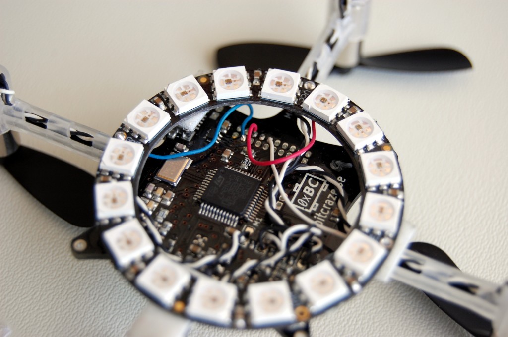
A couple of weeks ago we found the NeoPixel ring from Adafruit at a local shop, we had to attach this neat board to our copter and see what cool effect we could make with it. The ring has 16 RGB LEDs that can be driven independently with only one data wire. The LEDs the Neopixel contains are called WS2812.

This post is describing the development of a WS2812 driver for the Crazyflie. A later post will show the usage we did of it (fairly limited in comparison of the seemingly endless possibility, as usual we have more ideas than time to execute them :-).

The WS2812 LED

First of all we needed to see how to control the LEDs. The protocol used by the WS2812 is quite simple but special. All LED on the ring have a data input and a data output pin in a chained manner. Colors of the LED is send over the Data line to the first LED that will save it internally. When sending a second color the first LED will send the saved color to the second LED. And so on, by sending 16 color data we can set the color of all LEDs of the ring independently. Colors are sent as 24 bits (8 bits per component).

Up to there nothing is really peculiar, the system is pretty neat and allows to control a lot of LEDs with just one IO. The problems comes with the Bit encoding:

ws2812_format

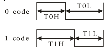
Bits are encoded with pulse width: a short pulse means 0 and a long pulse means 1. The bitrate is of about 800KHz and the tolerances on bit timing is pretty tight. As there is no hardware peripheral dedicated for this (on common microcontrollers), this bitstream needs to be implemented either by bit-banging or by being a bit creative with the peripheral we actually have at our disposal.

Driver implementation

Adafruit did implement a driver for the WS2812 for Arduino, this is a software implementation that uses the CPU to implement the signal. However at that bitrate a software/bit-bang implementation have to be timed carefully and the easiest for that is actually to implement it in assembler. Arduino runs on an AVR processor and these processor are very predictable: each instruction runs in a specified number of clock cycle which makes it possible to implement a timed loop like the one of Adafruit. However this becomes impractical on bigger CPU that implements caches and other optimization that makes it really hard to predict how much cycle each instruction will take.

The Crazyflie runs a STM32F103 based on an ARM Cortex-M3. This is just complex enough to make the ASM-timed loop impractical: The CPU core runs at 72MHz but the flash is slower so a simple cache memory is inserted in the middle and depending of the state of this cache it may take from 1 to 3 cycles to execute an instruction. There is an even bigger problem: a CPU timed loop requires to stop all interrupt and to have the CPU running exclusively on updating the WS2812. We cannot allow that on the Crazyflie that require a 250Hz control loop to stay (controllably) airborne.

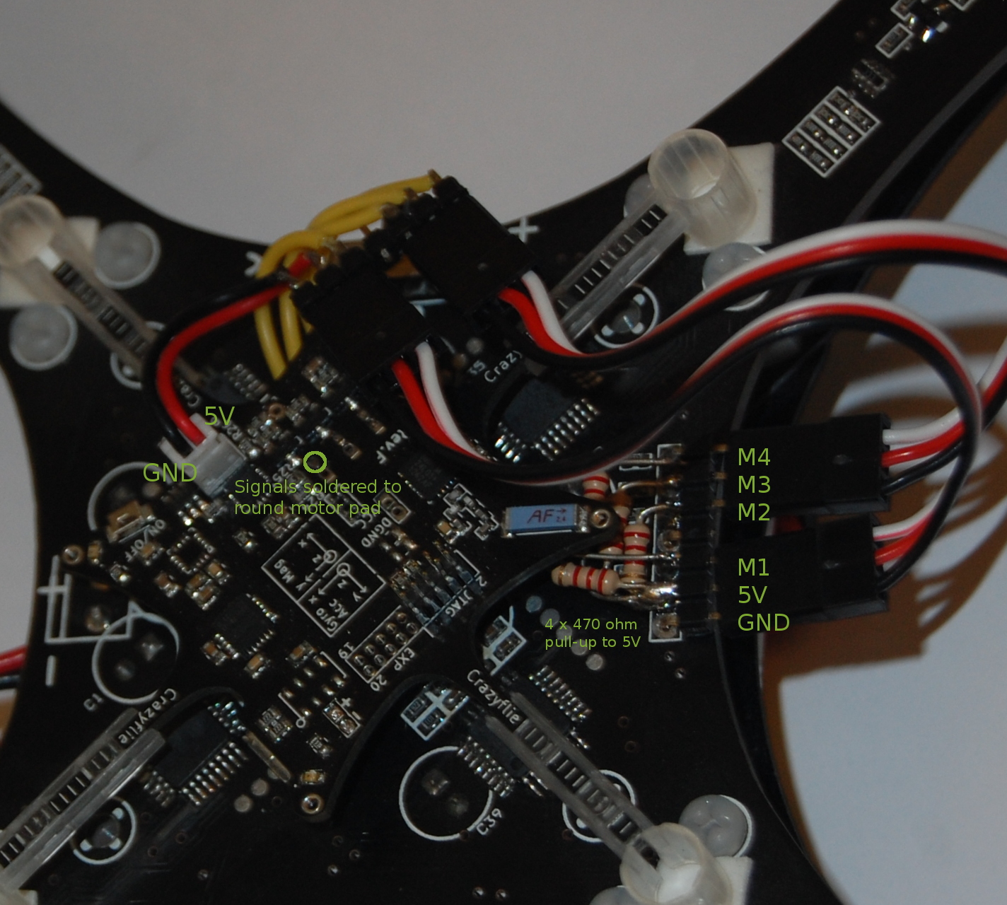
We asked Google to see if someone already came with a solution and actually someone did. The Elia’s Electronics Blog posted a neat, well documented, solution using the STM32 Pulse Width Modulation (PWM) capabilities of the STM32 to generate signals that the WS2812 understands. All we needed was a timer/pwm output then. It happens that we have one timer1 output on the Crazyflie extension port:

crazyflie_neopixelring

This is only 3 wires: VCOM for the battery voltage, GND and the timer output.

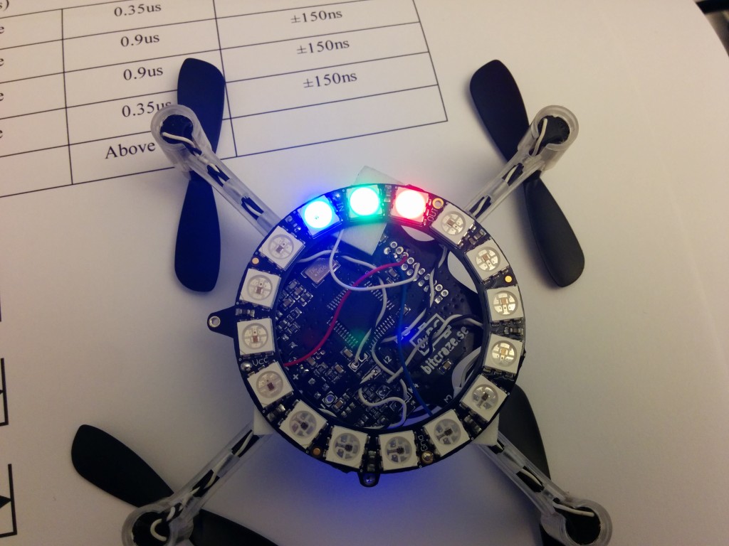
I started porting the Elia’s code to the Crazyfle. The only free timer we could easily use was different and much more complex than the one Elia uses. So part of the frustrating implementation was to figure out WHY the signal was looking weird on the scope! Finally after an hour or so the code was working:

IMG_20140411_202251

Enhancements

Now that was not quite enough. The driver is using the PWM to generate the 1’s and 0’s pulse width and the DMA is used to feed the bit width independently of the CPU (so that it can do something else, like controlling the copter attitude…). It requires all the 16 LEDs data to be written in the memory buffer before starting the DMA. Each LED has 24 bits color data and each bit will be encoded as 16bit pulse length for the timer. It means that the full ring will take 768Bytes in RAM. It sounds small but its a bit too much for us and, most importantly, it does not scale: if we want a second ring the ram requirement will double.

To fix this I implemented two things: An easy one is that the DMA can do some type conversion and one of these is that it can read 8 bit in memory and write 16 bit in the peripheral. This allows to store only 8 bits pulse width in memory and so divides by 2 the memory requirement, but it still doesn’t scale.

The fix to scaling is double buffering. The STM32F103 does not implement DMA double buffering as such but what it has is close enough: circular DMA with half-transfer interrupt. The idea is to load the 2 first LED in a buffer and to start the DMA for 42 bytes in circular mode. When the DMA has transferred the first LED it triggers the half-transfers interrupt which allows the CPU to replace the first LED data by the 3rd. When the 2nd LED is transferred the transfer-complete interrupt is triggered by the DMA and the CPU fills in the 4th LED in place of the 2nd one. The DMA roll-over at the beginning of the buffer and sends what is now the 3rd LED data. This continues until all the LEDs has been  sent. This solution scales: it requires a 42 bytes buffer for as many LED as we want!

Conclusion

All that process was not really simple. However the result is simple, now the only thing required to control a Neopixel ring in the Crazyflie is:


#define BLACK {0x00, 0x00, 0x00}</span>
static uint8_t color[][3] = {{40, 40, 40}, {32, 32, 32}, {16,16,16}, {8,8,8},
                             {4,4,4}, {2,2,2}, {1,1,1}, BLACK,
                             BLACK, BLACK, BLACK, BLACK,
                             BLACK, BLACK, BLACK, BLACK,
                            };

/* ... */
ws2812Send(color, 16);

And it will run nicely without interrupting other tasks like control and communication. Replace 16 by 32 to control 2 Neopixel rings. The current implementation has been pushed in the crazyflie-firmware neopixel_dev branch (still require some clean-ups!). Actual implementation is in ws2812.c and neopixelring.c.

neopixel_flying

The only problem left is not software: At the end of the battery life, the voltage is not enough to fully lit the blue LED. That make all white look orange-ish. The only way to fix this problem would be to step-up the battery voltage higher then the forward voltage of the blue LED. Though it works well enough without that.

Stay tuned for a following post about actual usage of the ring.

Most of last week was spent at the Devoxx France conference in Paris. Even though we didn’t have our talk until the end of the week, we hung around most of the time just developing and working. And of course we also got the chance to meet lots of interesting people and demo the Crazyflie. We worked on some code for the NeoPixel ring from Adafruit, implementing some different effects. We also did a quick hack to be able to change effects when flying using the Leap Motion. Since we haven’t had any time to prepare videos/photos of it and to clean up the code, we will post more about that next week.

We also got a chance to do some other fun things, like flying the FPV Crazyflie over the crowd at one of the keynotes and also record some video while flying though the conference.


[pe2-gallery album=”http://picasaweb.google.com/data/feed/base/user/115721472821530986219/albumid/6002584693333310545?alt=rss&hl=en_US&kind=photo” ]

This week we are heading off to Paris in France to present our project at Devoxx France. So if you are there and want to listen, then drop by the Ella Fitzgerald room at 10:40. The presentation will be in french and it will of course end with some demos :-) We will also hang around after the presentation just in case someone wants to test their flying skills. We are currently working on some nice light-effects using the Adafruit Neo Pixel ring that we will show off.

Also the Crazyflie is finally back in stock at Seeedstudio!

A while ago we posted a tutorial on how to modify the firmware to add logging/parameters and to plot/modify them from the client. We have done a continuation on this tutorial to show how to modify the client to integrate logging and parameters directly into the UI (like we have done on the flight tab). For the tutorial we use our virtual machine to do the development and running the code. Since we continue on the concepts and design made in the first video, it might be a good idea to see that one first.


A while ago I started working on a brushless motor control driver for the Crazyflie. I implemented most of it but did not really have time to test it. Recently we have gotten some request and questions about it so we took some time to do some further testing.

Implementing a brushless motor control driver can be done in many ways. If you have brushlesss motor controllers that can be controlled over I2C that could have been one way but usually the brushless motor controller (BLMC) take a PWM input. This is most commonly a square wave with a period of 20ms and a pulse width of 1-2 ms high, were 1 ms is 0%, and 2 ms is 100%. A period of 20 ms means a frequency of 50Hz. This is most often a high enough update rate for R/C electronics like servos etc. but when it comes to BLMC that is not the case. Therefore many new BLMC can read a much higher update rate of up to 400 Hz were the pulse still is 1-2 ms high. That way you can match the BLMC input to the update rate of the stabilization control loop and increase stability. In the code we added a define BLMC_PERIOD where this can be set.

To test this we wanted a frame which was quick to setup and found this. It is based of a PCB just like the Crazyflie and has the four motor controllers with it, perfect! The built in BLMC are based on an the Atmel MCU Atmega8 which is very commonly used in the R/C BLMC which means it is possible to re-flash them with the SimonK firmware. This is know to be a great firmware and enables fast PWM update rate etc. So we built and flashed the firmware configured for the tgy6a which is compatible and it worked right away, yay!

Now we only had to connect the Crazyflie to the BLMC:s on the frame. The BLMC electrical interface for the PWM signal is often a 5V interface but the Crazyflie runs on 2.8V. 2.8V would in most cases be treated as an high input and can probably be used directly but there is no simple way to connect this signal on the Crazyflie. Instead one way is to use the existing motor connectors and the pull-down capability that is already there. Then it is also possible to pull this signal to 5V with a resistor to get a 5V interface so this is what we did. To power the Crazyflie we took the connector of an old battery and soldered it the 5V output of the frame.CF to BL Frame connections

Now it was just a matter of testing it! However as size increases so does the potential damage it can make. We therefore took some precaution and tied it down. First we tested the stability on each axis using the stock values and it worked really well so we decided to not tune it further. The only issue was that suddenly one of the BLMC mosfets burnt. We replaced it and it worked again but don’t know why it burnt. Later when we flew it something was still strange so we have to investigate this.

We will upload the code as soon as it has been cleaned up. Please enjoy a short video of the journey :)