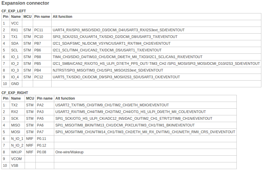
So last week we had a bit of fun connecting the Crazyflie 2.0 to a bigger quad frame. This is something we did a while ago with the Crazyflie Nano (1.0) , see this forum thread. This time it was the Crazyflie 2.0 turn and we wanted to use the deck port and the proto-deck so it would be easy to attach and remove, which is a great thing with the deck expansion port. Rewriting the current motor drivers would be the easiest way forward so finding 4 suitable timer outputs on the deck port was the first step. Looking at the pin mapping from the STM32F405 datasheet and the deck port you get something like this.
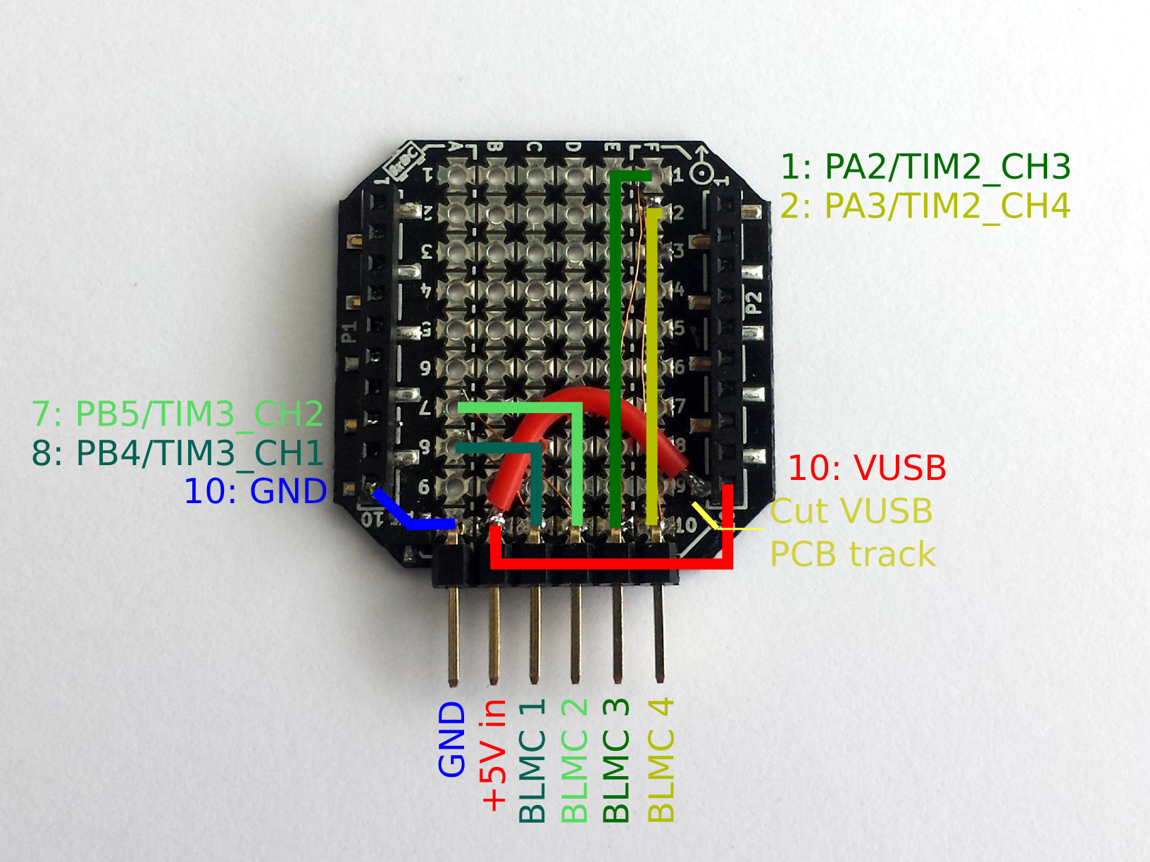
From this map one can identify a couple of timers and on pin 7,8 left as well as pin 1,2 right there are some suitable ones, TIM3_CH2, TIM3_CH1, TIM2_CH3 and TIM2_CH4 respectively. The timers will be used to generate a PWM control signal for the brushless motor controller (BLMC). As the deck port also has the VUSB input, from where the Crazyflie 2.0 can be powered (and charged), it can be externally powered from 4.5V – 6V. The Crazyflie 2.0 electronics consumes about 100mA without power optimization, can be good to keep in mind when powering it from something else. With all this information we took a prototype deck, a 2.54mm header, some small wire and got to work. As we already had a frame we wanted to interface with we tailored the output for this, but one could of course tailor it for other quad setups.
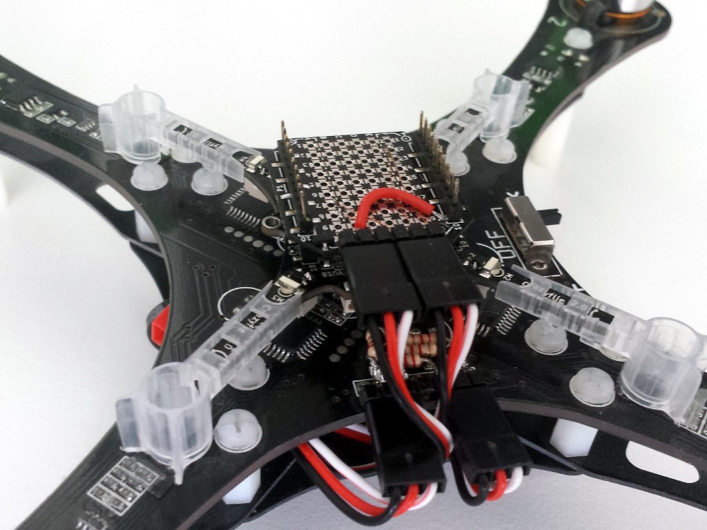
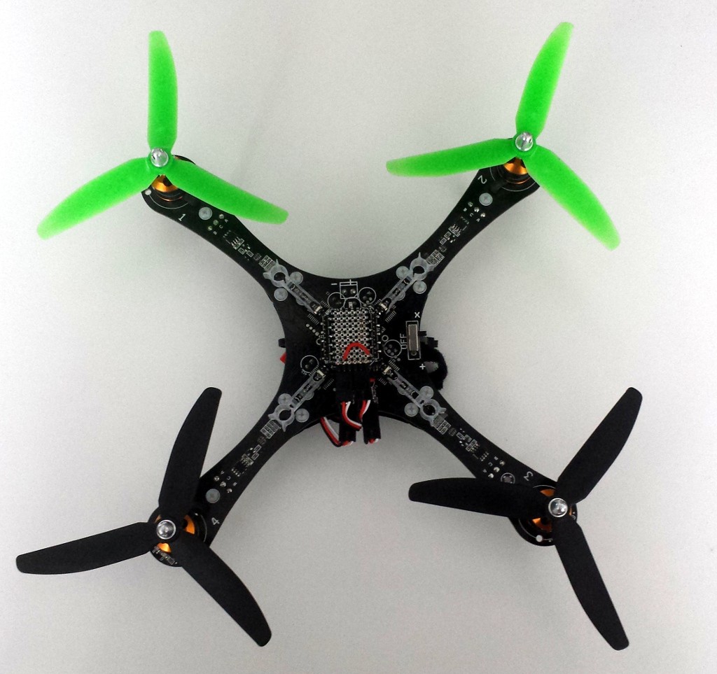
And viola, the final results looks like this.
We must inform you that this setup is very experimental, and as we are now dealing with dangerous things, much more care must be taken. So don’t do this if you don’t know what you are doing. The software also needs additional safety features before we think it is really usable in a bigger setup.
Next post will be about what to change in the software to make it all work, until then, happy hacking!
By the way Fred released a new version of the Android app last week, nicely done Fred!


