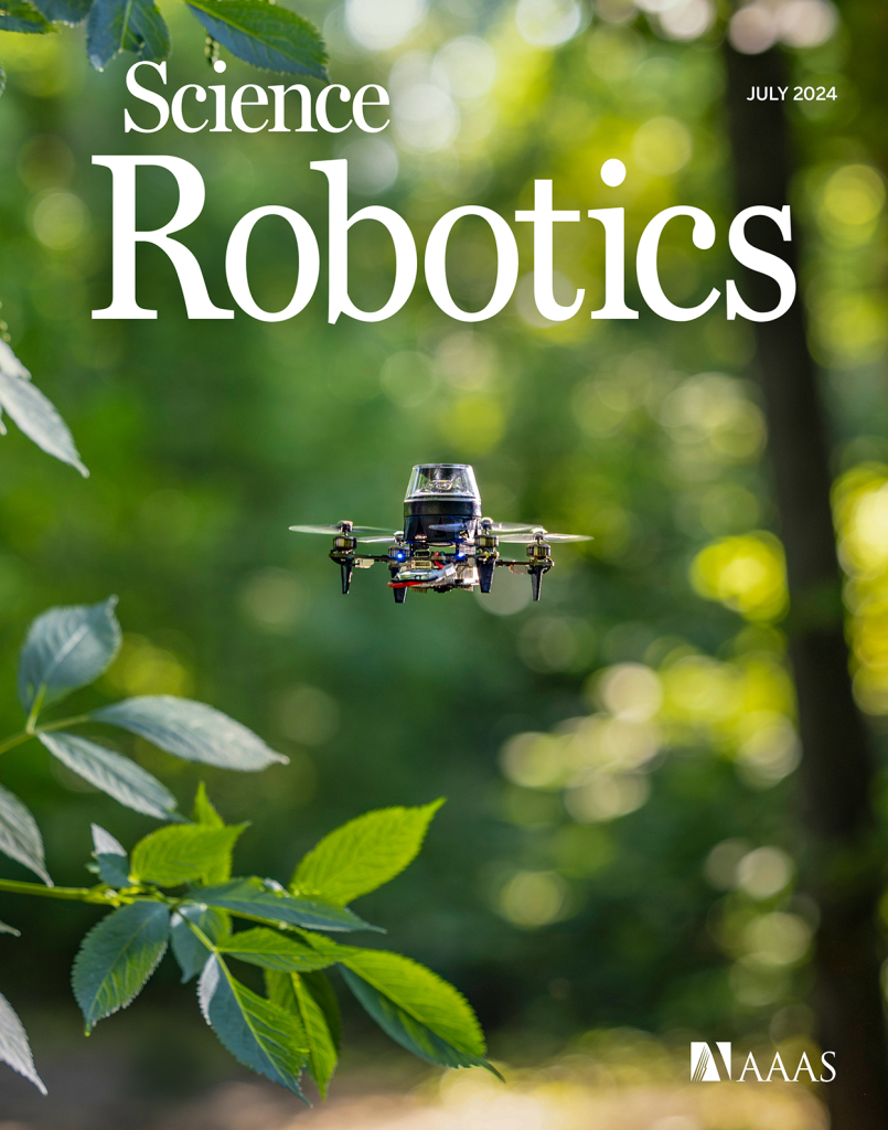
Drones can perform a wide range of interesting tasks, from crop inspection to search-and-rescue. However, to make drones practically attractive they should be safe and cheap. Drones can be made safer by reducing their size and weight. This causes less damage in a collision with people or the environment. Additionally, being cheap means that the drones can take more risk – as it is less expensive to lose one – or that they can be deployed in larger numbers.
To function autonomously, such a drone should at least have some basic navigation capabilities. External position references such as GPS or UWB beacons can provide these, but such a reference is not always available. GPS is not accurate enough in indoor settings, and beacons require prior access to the area of operation and also add an additional cost.
Without these references, navigation becomes tricky. The typical solution is to have the drone construct a map of its local environment, which it can then use to determine its position and trajectories towards important places. But on tiny drones, the on-board computational resources are often too limited to construct such a map. How, then, can these tiny drones navigate? A subquestion of this – how to follow previously traversed routes – was the topic of my MSc thesis under supervision of Kimberly McGuire and Guido de Croon at TU Delft, and my PhD studies. The solution has recently been published in Science Robotics – “Visual route following for tiny autonomous robots” (TU Delft mirror here).
Route following
In an ideal world, route following can be performed entirely by odometry: the measurement and recording of one’s own movements. If a drone would measure the distance and direction it traveled, it could just perform the same movements in reverse and end up at its starting place. In reality, however, this does not entirely work. While current-day movement sensors such as the Flow deck are certainly accurate, they are not perfect. Every time a measurement is taken, this includes a small error. And in order to traverse longer distances, multiple measurements are summed, which causes the error to grow impractically large. It is this integration of errors that stops drones from using odometry over longer distances.
The trick to traveling longer distances, is to prevent this buildup of errors. To do so, we propose to let the drone perform ‘visual homing’ maneuvers. Visual homing is a control strategy that lets an agent return to a location where it has previously taken a picture, called a ‘snapshot’. In order to find its way back, the agent compares its current view of the environment to the snapshot that it took earlier. The trick here is that the difference between these two images smoothly grows with distance. Conversely, if the agent can find the direction in which this difference decreases, it can follow this direction to converge back to the snapshot’s original location.

So, to perform long-distance route following, we now command the drone to take snapshots along the way, in addition to odometry measurements. Then, when retracing the route, the drone will routinely perform visual homing maneuvers to align itself with these snapshots. Because the error after a homing maneuver is bounded, there is now no longer a growing deviation from the intended path! This means that long-range route following is now possible without excessive drift.
Implementation
The above mentioned article describes the strategy in more detail. Rather than repeat what is already written, I would like to give a bit more detail on how the strategy was implemented, as this is probably more relevant for other Crazyflie users.
The main difference between our drone and an out-of-the-box one, is that our drone needs to carry a camera for navigation. Not just any camera, but the method under investigation requires a panoramic camera so that the drone can see in all directions. For this, we bought a Kogeto Dot 360. This is a cheap aftermarket lens for an older iPhone that provides exactly the field-of-view that we need. After a bit of dremeling and taping, it is also suitable for drones.

The very first visual homing experiments were performed on an ARDrone 2. The drone already had a bottom camera, to which we fitted the lens. Using this setup, the drone could successfully navigate back to the snapshot’s location. However, the ARDrone 2 hardly qualifies as small as it is approximately 50cm wide, weighs 400 grams and carries a Linux computer.
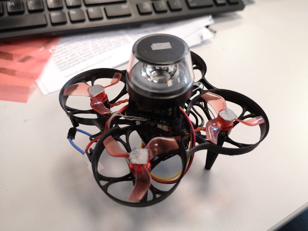
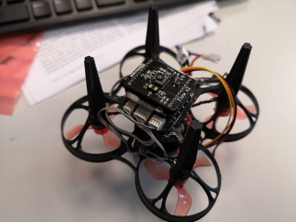
To prove that the navigation method would indeed work on tiny drones, the setup was downsized to a Crazyflie 2.0. While this drone could take off with the camera assembly, it would become unstable very soon as the battery level decreased. The camera was just a bit too heavy. Another attempt was made on an Eachine Trashcan, heavily modified to support both the camera, a flowdeck and custom autopilot firmware. While this drone had more than enough lift, the overall reliability of the platform never became good enough to perform full flight experiments.
After discussing the above issues, I was very kindly offered a prototype of the Crazyflie Brushless to see if it would help with my experiments. And it did! The Crazyflie brushless has more lift than the regular platform and could maintain a stable attitude and height while carrying the camera assembly, all this, with a reasonable flight time. Software-wise it works pretty much the same as the regular Crazyflie, so it was a pleasure to work with. This drone became the one we used for our final experiments, and was even featured on the cover of the Science Robotics issue.
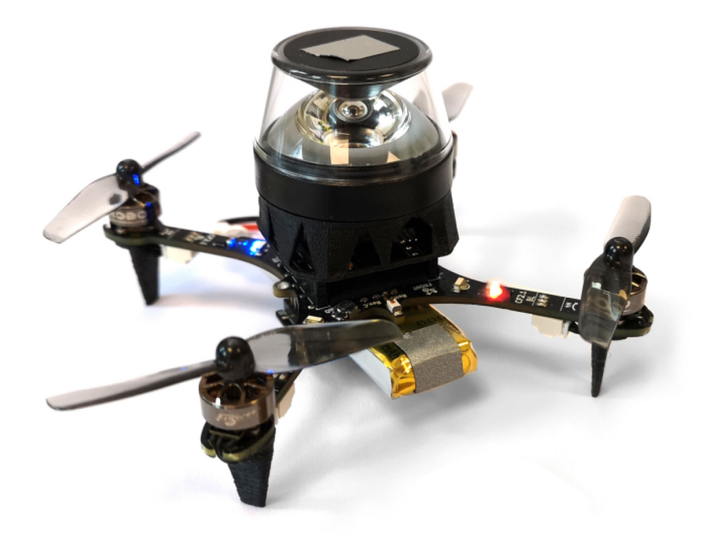
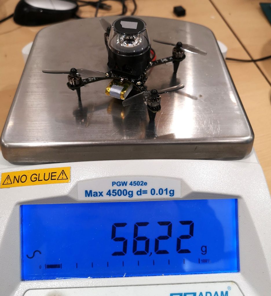
With the hardware finished, the next step was to implement the software. Unlike the ARDrone 2 which had a full Linux system with reasonable memory and computing power, the Crazyflie only has an STM32 microcontroller that’s also tasked with the flying of the drone (plus an nRF SoC, but that is out of scope here). The camera board developed for this drone features an additional STM32. This microcontroller performed most of the image processing and visual homing tasks at a framerate of a few Hertz. However, the resulting guidance also has to be followed, and this part is more relevant for other Crazyflie users.
To provide custom behavior on the Crazyflie, I used the app layer of the autopilot. The app layer allows users to create custom code for the autopilot, while keeping it mostly decoupled from the underlying firmware. The out-of-tree setup makes it easier to use a version control system for only the custom code, and also means that it is not as tied to a specific firmware version as an in-tree process.
The custom app performs a small number of crucial tasks. Firstly, it is responsible for communication with the camera. Communication with the camera was performed over UART, as this was already implemented in the camera software and this bus was not used for other purposes on the Crazyflie. Over this bus, the autopilot could receive visual guidance for the camera and send basic commands, such as the starting and stopping of image captures. Pprzlink was used as the UART protocol, which was a leftover from the earlier ARDrone 2 and Trashcan prototypes.
The second major task of the app is to make the drone follow the visual guidance. This consisted of two parts. Firstly, the drone should be able to follow visual homing vectors. This was achieved using the Commander Framework, part of the Stabilizer Module. Once the custom app was started, it would enter an infinite loop which ran at a rate of 10 Hertz. After takeoff, the app repeatedly calls commanderSetSetpoint to set absolute position targets, which are found by adding the latest homing vector to the current position estimate. The regular autopilot then takes care of the low-level control that steers the drone to these coordinates.
The core idea of our navigation strategy is that the drone can correct its position estimate after arriving at a snapshot. So secondly, the drone should be able to overwrite its position estimate with the one provided by the route-following algorithm. To simplify the integration with the existing state estimator, this update was implemented as an additional position sensor – similar to an external positioning system. Once the drone had converged to a snapshot, it would enqueue the snapshot’s remembered coordinates as a position measurement with a very small standard deviation, thereby essentially overwriting the position estimate but without needing to modify the estimator. The same trick was also used to correct heading drift.
The final task of the app was to make the drone controllable from a ground station. After some initial experiments, it was determined that fully autonomous flight during the experiments would be the easiest to implement and use. To this end, the drone needed to be able to follow more complex procedures and to communicate with a ground station.
Because the cfclient provides most of the necessary functions, it was used as the basis for the ground station. However, the experiments required extra controls that were of course not part of a generic client. While it was possible to modify the cfclient, an easier solution was offered by the integrated ZMQ server. This server allows external programs to communicate with the stock cfclient over a tcp connection. Among the possibilities, this allows external programs to send control values and parameters to the drone. Since the drone would be flying autonomously and therefore low-frequencies would suffice, the choice was made to let the ground station set parameters provided by the custom app. To simplify usability, a simple GUI was made in python using the CFZmq library and Tkinter. The GUI would request foreground priority such that it would be shown on top of the regular client, making it easy to use both at the same time.

To perform more complex experiments, each experiment was implemented as a state machine in the custom app. Using the (High-level) Commander Framework and the navigation routines described above, the drone was able to perform entire experiments from take-off to landing.
While the code is very far from production quality, it is open source and can be viewed here to see how everything was implemented: https://github.com/tomvand/2020-visualhoming-crazyflie . The PCB used to fit Crazyflie decks to the Eachine Trashcan can be found here: https://github.com/tomvand/cf-deck-carrier .
Outcome
Using the hardware and software described above, we were able to perform the route-following experiments. The drone was commanded to fly a preprogrammed trajectory using the Flow deck, while recording odometry and snapshot images. Then, the drone was commanded to follow the same route in reverse, by traveling short sections using dead reckoning and then using visual homing to correct the incurred drift.
As shown in the article, the error with respect to the recorded route remained bounded. Therefore, we can now travel long routes without having to worry about drift, even under strict hardware limitations. This is a great improvement to the autonomy of tiny robots.
I hope that this post has given a bit more insight into the implementation behind this study, a part that is not often highlighted but very interesting for everyone working in this field.
