Author: Tobias

If you have been reading our previous blog post you know that we redesigned the Crazyflie to use the MPU6050 instead of the IDG500-ISZ500-BMA145 combo. This was done because the IDG500 became obsolete, recently we found out it was because Invensens had production problems with this sensor, anyway when redesigning we managed to squeeze in a HMC5883l magnetometer and a MS5611 pressure sensor.  Now when we are getting close to actually making some kits we have to take some decisions and one of them is if we should build the Crazyflies with the HMC5883l magnetometer and the MS5611 pressure sensor mounted. This will of course increase the price which we have estimated to be about $20. Currently we do not use neither the magnetometer nor the pressure sensor. The yaw drift is so low that when you pilot the Crazyflie it isn’t noticeable and therefore we do not use the magnetometer. The pressure sensor we have just tested briefly and we do not really know how well it would work. Altitude hold might not be so useful inside but maybe outside.

Because of this little decision whether to mount the magnetometer and pressure sensor or not we would like to make a poll so please give us your thoughts.


Should we mount the pressure sensor and the magnetometer?

View Results

Loading ... Loading ...

One Sunday in March when we met up to work on the Crazyflie we suddenly realized that we do a lot of developing and discussing when we meet, but we don’t actually do that much flying. After realizing this we spent most of the Sunday just flying and playing around with the quadcopters.

So what could we try that we haden’t tried before…well we could try to crash each other while we are flying around: Crazyflie dogfight! The idea is that you should try to push the opponent out of the air without being dragged with him/her. This is easiest done by flying above the opponent making his/her crazyflie unstable and crash, however it is easier said then done!

This is not the first time two Crazyflies crash into each other in the air, but it’s the first time it’s actually intentional! It was a lot of fun but it can quickly end if something breaks. This dogfight however ended up with nothing to repair :-)

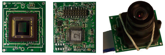
During this spring we have been involved in a Master thesis together with Epsilon. The goal for the thesis was to embed a camera module on the Crazyflie so it could be remotely controlled. Finding a lightweight camera module with access to documentation without buying a million units turned out to be trickier then we thought. The aptina MT9D131 was chosen as it can be bought from normal distributors, there is access to documentation and it has on-board JPG compression. The NRF24L01 radio was tested to see if it could handle low resolution video streaming, and it could, so no additional radio was needed. An addon board was built which could attach to the Crazyflie expansion port and it was called… Crazycam! (I wonder when we will become crazy for real :-)) . The Crazycam board uses the same STM32F103CB MCU that the Crazyflie uses to read out images from the camera chip.

Crazycam v0.1 (sensor side, mcu side, with mounted lens)

It turned out that the bandwidth to read out the images from the MT9D131 to the STM32 wasn’t enough and finding lightweight lenses was not that easy so the end result wasn’t as good as we hoped for. It wights about 5g and can stream images at about 6FPS. There are still things to try out and in theory it should handle 15-20FPS. It might be fixable so it ain’t over yet. If you would like to read the full report it is available at Linköpings university under the link “fulltext”. Even though we didn’t get all the way Thomas and Joakim, the authors, did a great job!

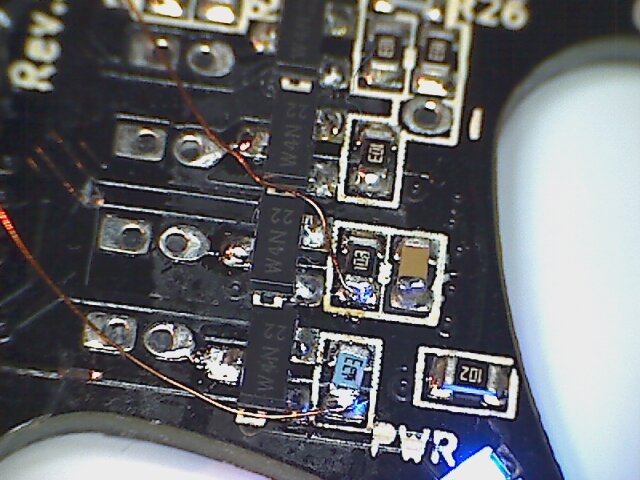
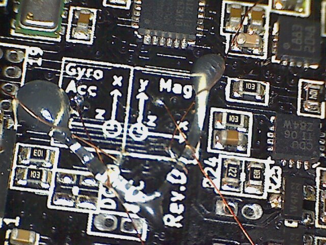
After investigating the problem with the MPU6050 from last week we found out that all our prototypes have defect MPU6050 sensors :-(. The bias offset values are way out of spec and several of the accelerometer axis is locked to their min or max value. The manufacturer must have dropped the hole batch in the floor or something because we would have expected at least one out of the six prototypes to have a working sensor. Without working sensors it is hard to make a maiden flight, which we are very eager to do. We will have to order new sensors and hopefully we can replace the new sensors without damaging them.

We also finished to patch all our test copters so that they will now be able to fly when we change the  sensor:


We don’t have that much new to write about this week. The software clean-up is slowly evolving and we have been working some more on the radio protocol and the ground station.

We hope that the new prototypes will be ready this week so maybe we could make a first flight with them in the beginning of next week :-)

A none return point has been passed as we have put in an order for a shit-load of motors. Now everything has to work out or we will be sitting with a hole bunch of motors and no money to do other fun stuff.


While we are waiting for our prototypes to arrive, the ETA is the 18th of may which is a looong wait, we thought we would play around with the Crazyflie outside now when spring has finally reached the south of Sweden. The drawback with a quadcopter this small is that it doesn’t work that well when it is windy outside but the upside is that it is pretty durable which makes great for some crazy testing :-). This Monday it was very calm outside and we got the idea to throw it in the air and try to make a “throwing start”. From the beginning we thought, no way, but it actually worked better then we thought. Here are some of the clips of  the more successful attempts :-)

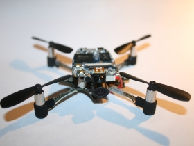
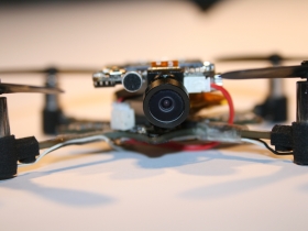
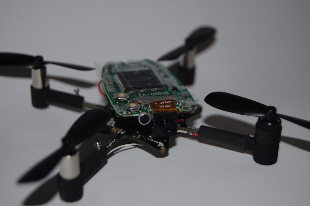
We also bought one of these very popular key chain spy cameras to try and get some on-board action footage. We removed the electronics from the casing, removed the battery and connected it to our battery instead. We even removed the mini-USB connector to save weight. It all ended up in about 25g including the Crazyflie which is OK. Now it is really starting to look as an insect of some sort…

Frame from onboard video footage

We managed to take a short on-board video but the camera doesn’t handle the battery voltage drop and resets pretty easily as soon as you hit the thrust. Maybe it is possible to power it from our stable 2.8V instead because now it is pretty useless. Also the view-angle is to narrow as well as the framerate being too low to get any good footage. We seem to have gotten the 808 #14 model which isn’t supposed to be the best. At least the Crazyflie is looking pretty mean with it attached :-). Further investigations will be done when we have some time left over.

We wish we had something interesting to write about, but recently we have just been cleaning up and reorganizing the Crazyflie firmware. We are doing this so it would be simpler to further develop the software when it is released. We have also been preparing the new drivers for the digital sensors so they will be ready when the next version of prototypes arrives within the next two weeks.

One funny thing we have though is this little teaser video we put together while testing the speed of the Crazyflie. It is not recommended crashing into something hard at this speed 8O

The last week we have been working hard on finishing the Crazyflie with the digital sensors, MPU-6050, HMC5883L and MS5611-01BA03. We are not so sure that the magnetometer,  HMC5883L, will work that well due to the strongly magnetized motors just a few centimeters from the sensor. That will be one of the upcoming tasks to find out.

Within 3-4 weeks we will receive what will hopefully be the final prototype version which later can be used for the first batch of Crazyflies. Until then we have plenty of work with software both on the PC side and the firmware. Now it is pretty late, the clock just passed 00:00 and writing at this hour is hard. We will post some video to compensate for this short post later this week :-)

When we built the latest prototypes we built two different versions. One with the ST accelerometer LIS344ALH and with the ISZ-IDG650 gyros. The other one with BOSH accelerometer BMA145 and with the ISZ-IDG500 gyros. It turned out that the LIS344ALH accelerometer is very vibration sensitive and doesn’t work that well for an application as this. If we would just have spent some time on the Internet we could have found this information in before hand… luckily we made the hardware design work with both and the BMA145 is working pretty well, however now we no longer have an alternative :-(.

The ISZ650 and IDG650 works pretty well even though they are less sensitive with their ±2000deg/s output. We can’t see any direct stability issues compared to the IXX500 versions with ±500deg/s output. Maybe we will stick with the IXX650, that way  we don’t limit the flip and loop speed to much. Not that the Crazyflie can do flips/rolls right now but we are very confident it will be able to in the future, judging from its agility.

We have also been working on getting the Crazyflie easier to control for beginners. With some slew rate limiting and thrust control we seem to be getting there. Now even Marcus can fly it without any problem. He used to hit the wall or ceiling all the time before :-).

We had to cancel our weekly Monday meeting due to illnesses but we have at least made some small progress we can write about.

The radio dongle code has been updated to flash either of the two LED’s when sending data or in case of bad transmission.

On our latest prototypes we discovered that the radio transmission went pretty bad on some copters as soon as the motors where turned on. This was not a nice discovery at this time of our project and we had not really seen it before. This kind of problem could require a big re-design of the PCB! After some debugging it turned out to be the PWM switching of the motors causing ripple on the digital supply voltage. It wasn’t that much, about 60mV peak-to-peak but enough to throw the radio off balance. After some tries with different decoupling techniques to get rid of the ripple, which showed only minor improvement, we increased the motor PWM frequency from 17kHz to 280kHz. That made the ripple go away, now about 10mV peak-to-peak, and so did the radio transmission problems, yeay!