We are excited to announce that we are working on several new link performance metrics for the Crazyflie that will simplify the troubleshooting of communication issues. Until now, users have had access to very limited information about communication links, relying primarily on a “link quality” statistic based on packet retries (when we have to re-send data) and an RSSI channel scan. Our nightly tests have been limited to basic bandwidth and latency testing. With this update, we aim to expose richer data that not only enables users to make more informed decisions regarding communication links but also enhances the effectiveness of our nightly testing process. In this blog post, we will explore the new metrics, the rationale behind their introduction, and how they will improve your interaction with the Crazyflie. Additionally, we will be holding a developer meeting on Wednesday November 13th to discuss these updates in more detail, and we encourage you to join us!
“Link Quality”—All or Nothing
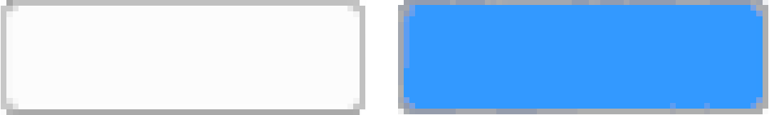
Until now, users of the Crazyflie have had access to a single link quality metric. Implemented in the Python library, this metric is based on packet retries—instances when data packets need to be re-sent due to communication issues. This metric indicates that for every retry, the link quality drops by 10%, with a maximum of 3 retries allowed. As a result, the link quality score usually ranges from 70% to 100%, with a drop to 0% when communication is completely lost. However, as packet loss occurs, users often experience a steep decline, commonly seeing 100% when packets are successfully acknowledged or dropping to 0% when communication is completely lost.
Client representation of link quality; no link, yes link
The current link quality metric has served as a basic indicator but provides limited insight, often making it difficult to gauge communication reliability accurately. Recognizing these limitations, we’re introducing several new link performance metrics to the Crazyflie Python library, designed to provide a far more detailed and actionable view of communication performance.
What’s Coming in the Upcoming Update
The first metric we are adding is latency. We measure the full link latency, capturing the round-trip time through the library, to the Crazyflie, and back. This latency measurement is link-independent, meaning it applies to both radio and USB connections. The latency metric exposed to users will reflect the 95th percentile—a commonly used measure for capturing typical latency under normal conditions.
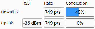
Next are several metrics that (currently) only support the radio link. For these, we distinguish between uplink (from the radio to the Crazyflie) and downlink (from the Crazyflie to the radio).
The first is packet rate, which simply measures the number of packets sent and received per second.
More interestingly, we are introducing a link congestion metric. Whenever there is no data to send, both the radio and the Crazyflie send “null” packets. By calculating the ratio of null packets to the total packets sent or received, we can estimate congestion. This is particularly useful for users who rely heavily on logging parameters or, for example, stream mocap positioning data to the Crazyflie.
The Received Signal Strength Indicator (RSSI) measures the quality of signal reception. Unlike our current “link quality” metric, we hope that a poor RSSI will serve as an early warning signal for potential communication loss. While RSSI tracking has been possible before with the channel scan example, this update will monitor RSSI in the library by default, and expose it to the user. The nRF firmware will also be updated to report RSSI by default. Currently, we only receive uplink RSSI, that is, RSSI measured on the Crazyflie side.
Work in progress client representation of new link performance metrics
We’ve already found these new metrics invaluable at Bitcraze. While we have, of course, measured various parameters throughout development, it was easy to lose track of the precise status of the communication stack. In the past, we relied more on general impressions of performance, but with these new metrics, we’ve gained a clearer picture. They’ve already shed light on areas like swarm latency, helping us fine-tune and understand performance far better than before.
You can follow progress on GitHub, and we invite you to try out these metrics for yourself. If there’s anything you feel is missing, or if you have feedback on what would make these tools even more helpful, we’d love to hear from you. Hit us up over on GitHub or join the developer meeting on Wednesday the 13th of November (see the join information on discussions).
We are happy to announce that release 2024.10 is now available! Special thanks to our community contributors for their valuable input and code contributions in this release!
We have some very busy weeks behind us and ahead! As we are working hard on releasing the new CF Brushless, we have been preparing for the upcoming ROSCon in Odense Denmark next week (see this previous blogpost) and we also featured on the latest OpenCV live episode as well! So more about both in this blogpost.
OpenCV Live! Demo Driven Development
We were featured as guests on the latest OpenCV Live! episode hosted by Phil Nelson and Satya Mallick, where we went through a bit of the history of the start of Bitcraze and all of the (crazy) demos done with the Crazyflie in the last decade. We have done a similar topic for our latest developer meeting, but for this episode we put the focus more on vision based demos, since OpenCV has been definitely used in the past at Bitcraze for various reasons! Just type in OpenCV in the top right search barto check out any of the blogs we have written.
During the OpenCV live episode of the 10th of October, Arnaud and Kimberly told the backstories of these demos that went from a manual flight fail where Arnaud flew the Crazyflie 1.0 in Marcus’ hair, using OpenCV and Aruco markers for positioning to flying a swarm in your kitchen. It was really fun to do and alos one lucky listener managed to answer the two questions the host Phil asked at the end, namely “Where does the name Crazyflie come from?” and “Why is the last part (‘-flie’) spelled this way?” and won a STEM ranging bundle. If you’d like to know the answers, go and watch the latest OpenCV! Live episode ;) Enjoy!
ROSCon – What to expect?
So next week we will be present as Silver Sponsor at ROSCon Odense, namely on Monday 21th and Wednesday 23rd of October. The Bitcraze booth will be located on number 21 so that should be near the coffee break place! We will have are old trusty cage with some upgrades with a nice ROS demo which is similar to the one explained in this Crazyflie ROS tutorial we have written a while ago, but then the swarming variant of it. We also hope to show a Brushless Crazyflie Prototype, and a new camera deck prototype, along with anything else we can find lying around at our office :D.
Moreover, Arnaud will be given a presentation on the lighthouse positioning system, namely at Wednesday 23rd of October 14:40 (2:30 pm) called ‘The Lighthouse project: from Virtual Reality to Onboard Positioning for Robotics’. The lighthouse positioning system will also be the system that we will demo at our booth so if you’d like to see it for yourself, or perhaps (during downtime) hack around together with us, you are more than welcome to do so! Check out the Bitcraze ROSCon Eventpage for more details about our demo or the hardware we will show.
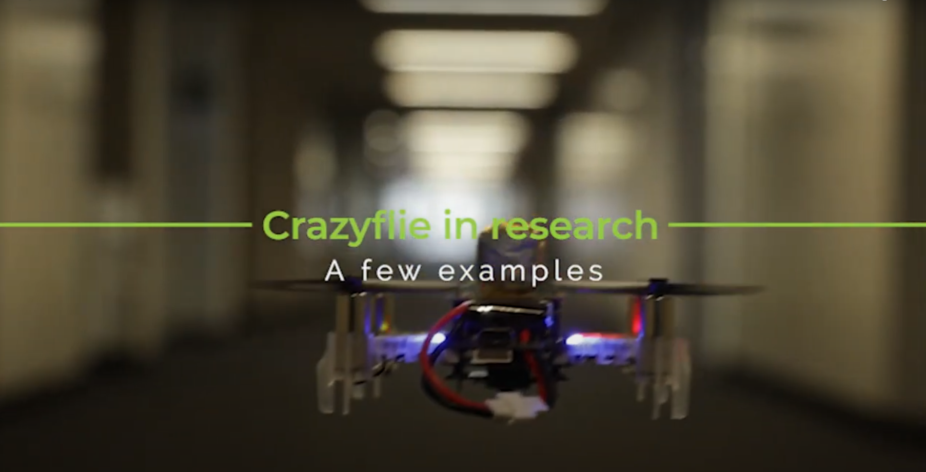
It’s now become a tradition to create a video compilation showcasing the most visually stunning research projects that feature the Crazyflie. Since our last update, so many incredible things have happened that we felt it was high time to share a fresh collection.
As always, the toughest part of creating these videos is selecting which projects to highlight. There are so many fantastic Crazyflie videos out there that if we included them all, the final compilation would last for hours! If you’re interested, you can find a more extensive list of our products used in research here.
The video covers 2023 and 2024 so far. We were once again amazed by the incredible things the community has accomplished with the Crazyflie. In the selection, you can see the broad range of research subjects the Crazyflie can be a part of. It has been used in mapping, or swarms – even in heterogeneous swarms! With its small size, it has also been picked for human-robot interaction projects (including our very own Joseph La Delfa showcasing his work). And it’s even been turned into a hopping quadcopter!
Here is a list of all the research that has been included in the video:
Energy efficient perching and takeoff of a miniature rotorcraft Yi-Hsuan Hsiao, Songnan Bai, Yongsen Zhou, Huaiyuan Jia, Runze Ding, Yufeng Chen, Zuankai Wang, Pakpong Chirarattananon City University of Hong Kong, Massachusetts Institute of Technology, The Hong Kong Polytechnic University
But enough talking, the best way to show you everything is to actually watch the video:
A huge thank you to all the researchers we reached out to and who agreed to showcase their work! We’re especially grateful for the incredible footage you shared with us—some of it was new to us, and it truly adds to the richness of the compilation. Your contributions help highlight the fantastic innovations happening within the Crazyflie community. Let’s hope the next compilation also shows projects with the Brushless!
There is one thing that has driven both the hardware/software and our enthusiasm forward in the last 13 years, and that is making demos! Whether it’s a new piece of hardware/deck for the Crazyflie or the integration with an existing software framework, it doesn’t matter, but we have got to show it and, by all means… it needs to fly!
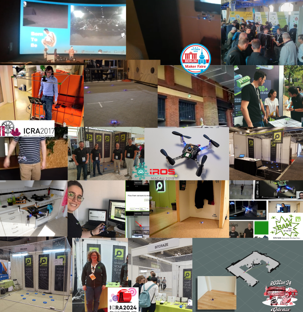
We have used fairs, conferences, and online meetings as perfect opportunities to push the capabilities of the little Crazyflie to the fullest. Of all the development goals we set, those self-made deadlines and over-ambitiousness have pushed both the hardware and software to the limit. In this blog post, we will take a look back at all of those demos we’ve done in the past and what we have learned from them.
2013 – 2017: Hacker and Developer Fairs
One of the very first conferences we were invited to was Devoxx in the UK. This was back in 2013, and we flew the Crazyflie (1) with an FPV camera over the actual crowd (blogpost, video), which was something we had already been working on for about half a year before showing it at the conference (blogpost, video). A year later, at Devoxx France (2014), they let us fly at the actual exhibition and over the booths, which showed much better quality (blogpost, video)! Not sure if they would still let us do this at fairs, but back then it was a bit of a wild west :D.
By the time the Crazyflie 2.0 was released, we started going to Makerfaires and even visited 3 of them, all in 2015! At the Makerfaire in the Bay Area (blogpost), New York, and Berlin (blogpost 1, blogpost 2), we prepared an external positioning system with the Kinect 2 and augmented reality markers (ArUco) (blogpost). That was one hectic year, and not without issues with the demo itself along the way (blogpost), but it showcased the Crazyflie and pushed the Crazyflie Python library and client to a more mature state.
Once 2016 came, the ultra-wideband positioning hacks reached a point where we could start demoing them as well. At first, the positioning was still calculated offboard with a ROS(1) node and transmitted to the Crazyflie, which was first showcased at Makerfaire Berlin 2016 (blogpost, video) at the booth itself. Eventually, a live demo was given at FOSDEM 2017 in the actual devroom for Embedded, Mobile, and Automotive (talk page). The Flowdeck was also in development at that time, and we had a small tabletop demo at Makerfaire Shenzhen 2017, where people could press a button, and the Crazyflie would take off, fly a circle, and land again (blogpost, video).
2017 – 2019: Academic Robotics Conferences
From 2017, we made it a habit to also meet with our research users, so we started going to academic robotics conferences as well, starting with ICRA 2017 in Singapore. Here, we showcased the Loco Positioning System, where the positioning was estimated onboard, so no external computer was required to perform the calculations (blogpost, video).
At IROS 2018, we took it up a notch by joining our collaborator Qualisys, showcasing the Loco Positioning System for a swarm, Motion Capture-based localization, and the brand new Lighthouse positioning prototype (blogpost 1, blogpost 2). We also added autonomous charging to it as well, so it was a great deal of work! Maybe we took on a bit too much, but one thing is for sure—we learned a lot by doing it (blogpost 1, blogpost 2, video)! With ICRA and IROS 2019, we perfected the circling swarm demo so that it was fully autonomous. However, this time we only used the Lighthouse positioning system since it was a bit easier to set up (blogpost 1, blogpost 2, video). The computer still had to command which Crazyflie to start flying, but other than that, we didn’t have to mind it that much and had plenty of time to talk with the users.
2020 – 2022: Covid and the Home Lab
As everyone knows—and probably tries to forget—2020 was the year that Covid hit us hard, and we couldn’t travel anywhere anymore. For us, it was quite an adjustment period, as we had to find another type of motivation to keep moving forward and continue development. We introduced the concept of the home lab and gave online talks and tutorials to still show cool stuff with the Crazyflie to the world (blogpost, video).
In 2020, we all joined together to work on the Hyper demo, which was a showcase that demonstrated the Crazyflie could fly with three positioning systems at the same time, enabling it to fly all the way from the meeting room to the flight arena (blogpost, video). We also celebrated Bitcraze’s 10-year anniversary with the BAM Days, a full 3-day online seminar about all things Crazyflie, for which we and our collaborators prepared a whole range of different demos, including a Rust-based app layer example and a peer-to-peer onboard swarming example (blogpost).
2022-now: Back to conferences
At the end of 2022, we managed to go to fairs again, namely IMAV and IROS 2022, where we showcased the fully autonomous swarm demo as before Covid hit. However, due to the demos we conducted during Covid, we also added full onboard peer-to-peer communication. This enabled the Crazyflies to negotiate which Crazyflie could take off, which pretty much completely eliminated the need for an external computer. Moreover, the Crazyflies communicated their positions to each other, which made it possible for them to avoid collisions on the fly (blogpost, video).
We have shown this demo as well for ICRA 2023 in London (blogpost) and ICRA 2024 in Yokohama (blogpost) with different variations and the upcoming brushless version as well (blogpost). The demo is quite robust, but it’s great to learn about the quality of the new motors and props, the guard prototypes of the Crazyflie Brushless, and the flight stability. But as you know us by now, it is time for something different!
Soon – ROSCon 2024
We have been to ROSCon before, back in 2022 (blogpost), but now we will be going to ROSCon 2024 for the first time as exhibitors (blogpost). ROS is a framework that is used by many researchers, including our users through Crazyswarm2, but ROSCon is more developer-oriented, and there will be more companies present that focus more on industry than academia. This time we won’t show our swarm demo as we usually do, but we will be showing demos more in line with what is presented in the ROS skill learning session of the robotics developer day (blogpost, video), but we will be hacking around on the spot! So this will be something new for us to try out, and we are very much looking forward to it!
Developer meeting, 9th of October 2024
This blog post only represents a subset of demos that we have done, but we will go into further detail at the next developer meeting on Wednesday, the 9th of October, at 3 PM CEST! Please join us to learn about all the great demos we have done in the past, get a glimpse of the history of Bitcraze, and discuss why demo-driven development is so important in moving your development forward.
Ever since we started going to fairs to show off the Crazyflies, we’ve been trying to push the boundaries for the demos. Often we’ve used the fairs as an opportunity to either develop new functionality or try out new ideas. Something we’ve always been interested in, especially for fairs, is autonomous flights. It’s hard to talk to people about the Crazyflie while trying to fly it at the same time. Back in 2015 we were using the Kinect for piloting the Crazyflie at the Bay Area Maker Faire. Although awesome, we had a slight issue: we needed to switch batteries on the Crazyflie each flight. We had a Qi deck for wireless charging but no positioning system good enough to use it for landing on a charger.
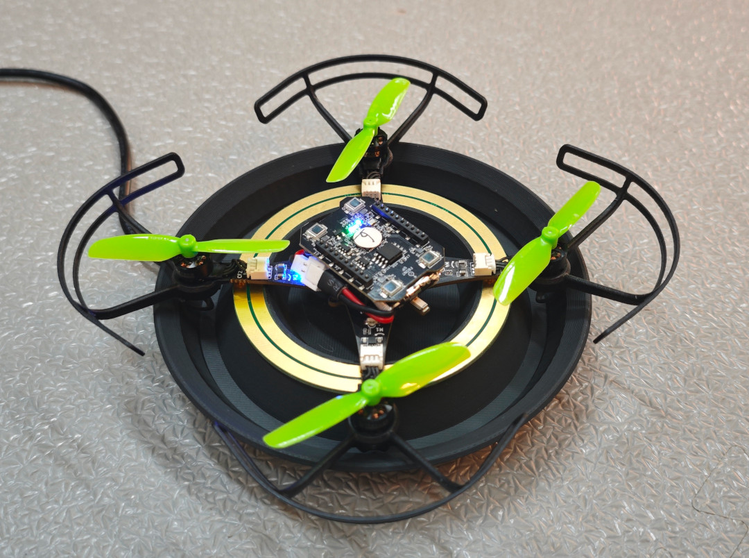
Latest iteration of the Crazyflie Brushless charger
In 2018 we were really excited when we got to borrow a motion capture system from Qualisys and could finally land on a Qi charger (3D printed base and an IKEA Qi charger). First time we showed this off was at IROS in Madrid 2018. The following year we improved the demo to have more Crazyflies and switched to the Lighthouse positioning system at ICRA 2019. Since then each year we have been improving the demo until we’ve reached the current state we showed off at IROS 2022 in Kyoto.
So since 2018 we’ve been using the Qi wireless charging for our demos. Many customers have purchased the Qi charging deck, but building a matching charging platform has always required some effort. So, a while back we started looking at something that could replace the Qi deck, with a lighter solution which would also allow users to have other decks with electronics facing downwards. The first prototypes were made with the Crazyflie 2.1 back in 2021 using decks, but they were a bit clumsy. For one thing you needed the charging solution to be integrated on each deck.
When work started on the Crazyflie Brushless we realized we had the possibility to integrate the charge points directly on the main PCB which meant we could still use any decks we wanted and get the charging. So the prototypes from 2021 were reshaped into something we could use with the Crazyflie Brushless. Although the prototypes worked well, they were pretty big and packed with features which weren’t needed for charging (like LED lights and WiFi). Another iteration and the chargers have now gone down in size and complexity. The latest iteration only has charging and is powered via our 12V power block or 5V USB-C.
Over the years lots of customers have asked us for buying the Qi charger, since many users do not have the capabilities to build their own. Unfortunately we’ve never gotten around to it, but with the release of the Crazyflie Brushless we would like to change this. The release is only a few months away so we’re short on time for remaking the design so it’s usable for plastic molding. Instead the plan is to make a limited amount of prototypes available to our users, based on the same 3D printed design and electronics we’re currently using in our flight lab, at the time of release. This will enable our users to easily try out the design and create their own autonomous demos which will keep flying for a long time.
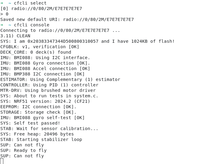
As you might expect, we use the Crazyflie python client a lot at Bitcraze. The client has a lot of features, ranging from setting up LPS/Lighthouse systems to turning on/off the headlight LEDs on the LED-ring deck. But some of the features we use the most is probably the console view as well as the logging/parameter subsystems. A lot of the time we modify firmware, flash it and want to tweak (via parameters) or to check if the changes are working as expected (via the console or logging). Then switching from the terminal, where we build/flash, to the Qt UI in the Crazyflie python client can be a hassle if you just want to do something quick. It would be great to be able to log/set variables directly from the terminal, well now you can!
Meet the Crazyflie command-line client, a fun Friday project I worked on a while back. The CLI is written in Rust and was made possible thanks to a previous fun Friday project by Arnaud on the Rust Crazyflie link/lib, which has now moved to the official Bitcraze repositories. The CLI project is still very limited, but has some basic functionality:
Scan for Crazyflies and pre-select one to interact with
List loggable variables, create log configurations and print their value
List parameters and get/set them
Show the Crazyflie console
Last week the first version, v0.1.0, was released on crates.io. So if you have Rust set up on your computer and want to test it out then all you need to do is to type “cargo install cfcli“. The CLI still only has some basic functionality, but hopefully it can be expanded in the future with more useful things! Feel free to leave any issues or comments you might have on the Github page.
ROSCon is a developer’s conference that focuses entirely on the Robot Operating System (ROS), bringing together developers from around the globe to learn, discuss, and network. It serves as a space for ROS developers to explore the latest advancements, share their experiences, and collaborate on cutting-edge robotics projects. We attended ROSCon 2022 in Japan, and it was a fantastic experience. So when the opportunity came to participate again this year, we couldn’t pass it up! Not only is this a conference that’s been close to our hearts, this year it’s also close to the office: it’s merely a 3hours train ride away.
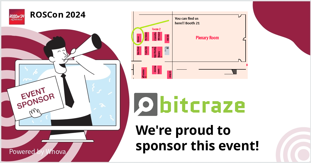
The 2024 edition is full of promises already, and we’re excited to be a part of it in several ways. We talked about how we helped out the diversity committee already, contributing to efforts that promote a more inclusive and diverse community within the robotics field. Moreover, we will have a booth there. We’ll be located at in Room 2, at booth 21. If you have trouble finding us, just listen closely to the sound of drones buzzing! ! We’ll be showcasing a live demo that’s still under construction. If you’re curious and want to know more about it, just keep an eye on our weekly blogposts to get an update once we finalize our plans.
In addition to being an exhibitor, we also have the honour of presenting a talk. Arnaud will be speaking on October 23 at 14:40 in Large Hall 4. His talk, titled “The Lighthouse Project: From Virtual Reality to Onboard Positioning for Robotics”, will dive into the Lighthouse system, as the title implies. He’ll explain how this technology, originally developed for virtual reality, is being adapted for onboard positioning in various types of robots.
We’re really looking forward to connecting with fellow developers, learning from the presentations, and sharing our own work with the community. If you’re attending ROSCon 2024, be sure to stop by Booth 21 and catch Arnaud’s talk—we can’t wait to see you there!
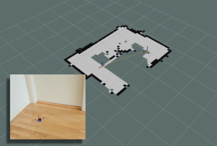
You might remember that at the beginning of this summer, we were invited to do a skill-learning session with the Crazyflie at the Robotics Developer Day 2024 (see this blog post) organized by The Construct. We showed the Crazyflie flying with the multi-ranger deck, capable of mapping the room in both simulation and the real world. Moreover, we demonstrated this with both manual control and autonomous wall-following. Since then, we wanted to make some improvements to the simulation. We now present an updated tutorial on how to do all of this yourself on your own machine.
Note: This tutorial was originally developed for a demonstration at Robotics Developer Day 2024. As the integration depends on specific versions of ROS 2, Gazebo, and related packages, it may require adjustments to work with current software. This post is no longer actively maintained by the Bitcraze team.
This tutorial will focus on using the multi-ranger ROS 2 nodes for both mapping and wall-following in simulation first, before trying it out on the real thing. You will be able to tune settings to your specific environment in simulation first and then use exactly the same nodes in the real world. That is one of the main strengths of ROS, providing you with that flexibility.
We have made a video of what to expect of the tutorial, for which you should use this blogpost for the more detailed instructions.
Watch this video first and then again with the instructions below
What do you need first?
You’ll need to setup some things first on the PC and acquire hardware to follow this tutorial in full:
Gazebo Harmonic – Install via these instructions This is not the recommended Gazebo for humble but we will install the specific ROS bridge for this later. Just make sure that you don’t have gazebo classic installed on your machine.
Hardware
You’ll need to components at least of the STEM ranging bundle
If you have any different setup of your computer or positioning system, it is okay as the demos should be simple enough to work, but, be prepared for some warning/error handling that this tutorial might have not covered.
Time to complete:
This is an approximation of how much time you need to complete this tutorial, depended on your skill level, but if you already have experience with both ROS 2/Gazebo and the Crazyflie it should take 1 hour.
If you have the Crazyflie for the first time, it would probably be a good idea to go through the getting started tutorial and connect to it with a CFclient with the Flowdeck and Multi-ranger deck attached as a sanity check if everything is working before jumping into ROS 2 and Gazebo.
Go to the ros2_ws workspace and build the packages
cd ~/crazyflie_mapping_demo/ros2_ws/
source /opt/ros/humble/setup.bash
colcon build --cmake-args -DBUILD_TESTING=ONCode language:JavaScript(javascript)
Building will take a few minutes. Especially Crazyswarm2 will show a lot of warnings and std_err, but unless the package build has ‘failed’, just ignore it for now until we have proposed a fix to that repository.
If the build of all the packages passes and non failed, please continue to the next step!
2. Simple mapping simulation
This section will explain how to create a simple 2D map of your environment using the multi-ranger. The ROS 2 package designed for this is specifically made for the multi-ranger, but it should be compatible with NAV2 if you’d like. However, for now, we’ll focus on a simple version without any localization inferred from the map.
Open up a terminal which needs to be sourced for both the gazebo model and the newly build ROS 2 packages:
If you get a ‘No such file or directory’ error on the model, try entering the full path in GZ_SIM_RESOURCE_PATH export.
Gazebo will start with the Crazyflie in the center. You can get a close-up of the Crazyflie by right-clicking it in the Entity tree and pressing ‘Move to’. You can also choose to follow it, but the camera tracking feature of Gazebo needs some tuning to track something as small as the Crazyflie. Additionally, you will see RVIZ starting with the map view and transforms preconfigured.
Open up another terminal, source the installed ROS 2 distro and open up the ROS 2 teleop keyboard node:
source /opt/ros/humble/setup.bash
ros2 run teleop_twist_keyboard teleop_twist_keyboard
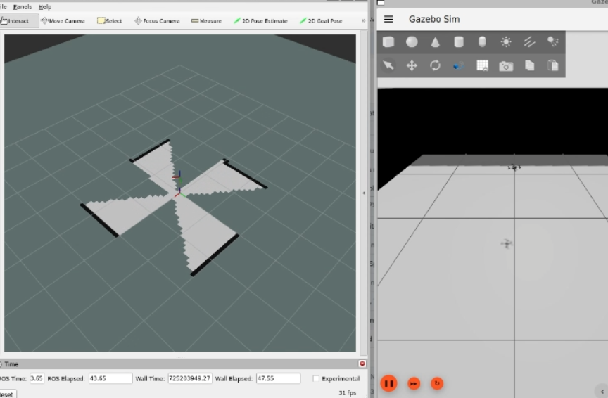
Have the Crazyflie take off with ‘t’ on your keyboard, and rotate it around with the teleop instructions. In RVIZ you should see the map being created and the transform of the Crazyflie moving. You should be able to see this picture, and in this part of the video.
Screenshot of the Crazyflie in Gazebo generating a map with Teleop (video)
3. Simple mapping real world
Now that you got the gist of it, let’s move to the real Crazyflie!
First, if you have a different URI of the Crazyflie to connect to, first change the config file ‘crazyflie_real_crazyswarm2.yaml’ in the crazyflie_ros2_repository. This is a file that Crazyswarm2 uses to know to which Crazyflie to connect to.
Open up the config file in gedit or your favorite IDE like visual code:
and change the URI on this line specifically to the URI of your Crazyflie if necessary. Mind that you need to rebuild ros2_ws again to make sure that this has an effect.
Now source the terminal with the installed ROS 2 packages and the Gazebo model, and launch the ROS launch of the simple mapper example for the real world Crazyflie.
Now open up another terminal, source ROS 2 and open up teleop:
source /opt/ros/humble/setup.bash
ros2 run teleop_twist_keyboard teleop_twist_keyboard
Same thing, have the Crazyflie take off with ‘t’, and control it with the instructions.
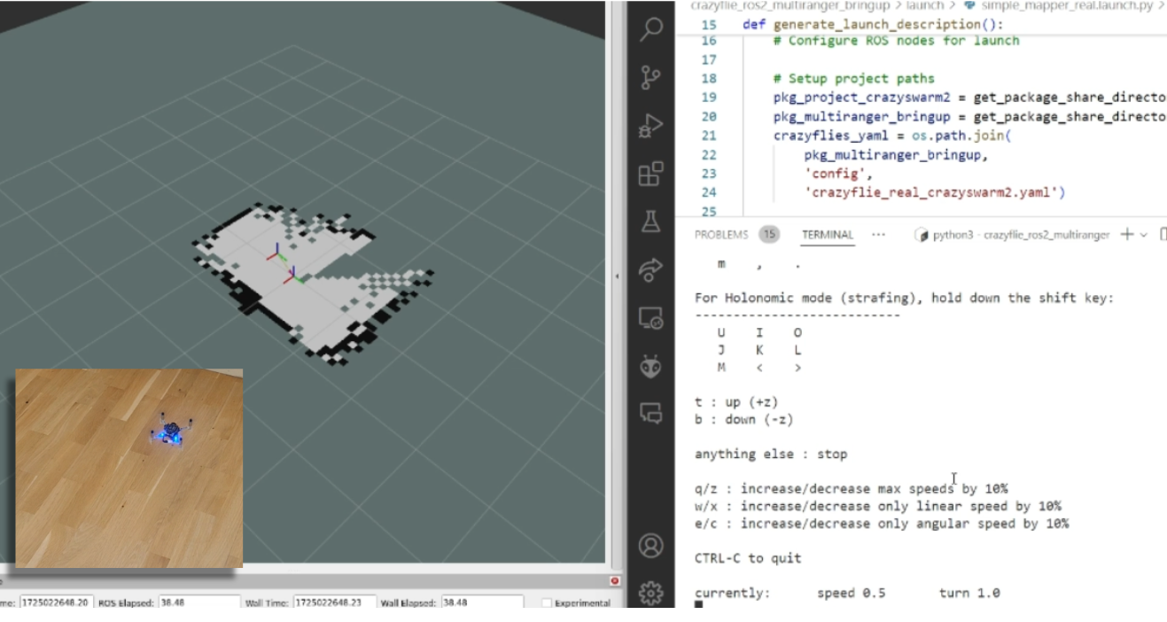
You should be able to see this on your screen, which you can also check with this part of the video.
Screen shot of the real Crazyflie mapping while being controlled with ROS 2 teleop (video)
Make the Crazyflie land again with ‘b’, and now you can close the ROS 2 node in the launch terminal with ctrl + c.
4. Wall following simulation
Previously, you needed to control the Crazyflie yourself to create the map, but what if you could let the Crazyflie do it on its own? The `crazyflie_ros2_multiranger` package includes a `crazyflie_ros2_multiranger_wall_following` node that uses laser ranges from the multi-ranger to perform autonomous wall-following. Then, you can just sit back and relax while the map is created for you!
Let’s first try it in simulation, so open up a terminal and source it if you haven’t already (see section of the Simple mapper simulation). Then launch the wall follower ROS 2 launch file:
Take off and wall following will go fully automatic. The simulated Crazyflie in Gazebo will fly forward, stop when it sees a wall with it’s forward range sensor and follow the wall on its left-hand side.
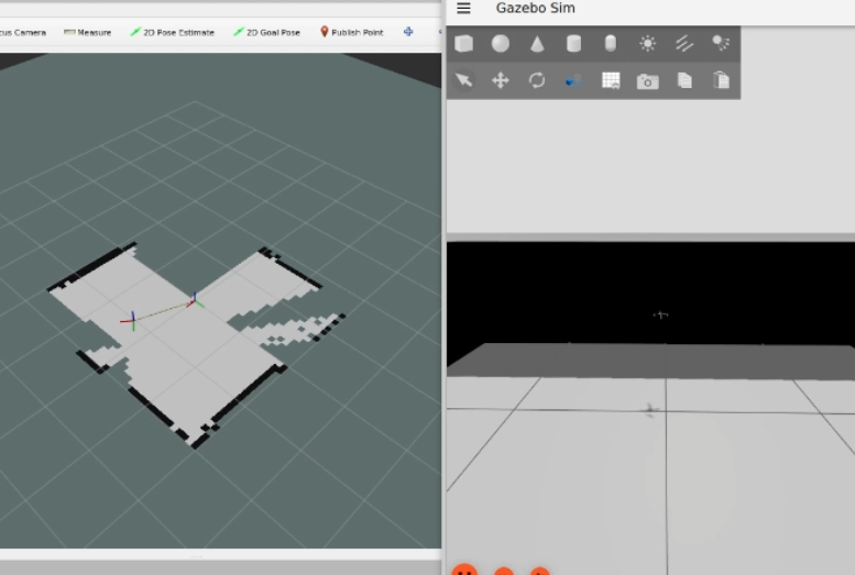
You’ll see on RVIZ2 when the full map is created like here below and this part of the tutorial video.
Screenshot of the simulated Crazyflie in Gazebo mapping will autonomously wall following (video)
You can stop the simulated Crazyflie by the following service call in another terminal that is sourced with ROS 2 humble.
ros2 service call /crazyflie/stop_wall_following std_srvs/srv/Trigger
The simulated Crazyflie will stop wall following and land. You can also just close the simulation, since nothing can happen here.
5. Wall following real world
Now that we have demonstrated that the wall-following works in simulation, we feel confident enough to try it in the real world this time! Make sure you have a fully charged battery, place the Crazyflie on the floor facing the direction you’d like the positive x-axis to be (which is also where it will fly first), and turn it on.
Make sure that you are flying with a room with clear defined walls and corners, or make something with cardboard such as a mini maze, but the current algorithm is optimized to just fly in a squarish room.
Source the ROS 2 workspace like previously and start up the wall follower launch file for the
Like the simulated Crazyflie, the real Crazyflie will take off automatically and automatically do wall following, so it is important that it is flying towards a wall. It should look like this screenshot, or you can check it with this part of the video.
The real crazyflie wall following autonomously while mapping the room (video).
Be careful here to not accidently run this script with the Crazyflie sitting on your desk!
If you’d like the Crazyflie to stop, don’t stop theROS2 nodes with ctrl-c, since it will continue flying until crash. It’s not like simulation unfortunately where you can close the environment and nothing will happen. Instead, use the ROS 2 service made for this in a different terminal:
ros2 service call /crazyflie_real/stop_wall_following std_srvs/srv/Trigger
Similar the real Crazyflie will stop wall following and land. Now you can close the ROS 2 terminals and turn off the crazyflie.
Next steps?
We don’t have any more demos to show but we can give you a list of suggestions of what you could try next! You could for instance have multiple Crazyflies mapping together like in the video shown here:
This uses the mapMergeForMultiRobotMapping-ROS2 external project, which is combined with Crazyswarm2 with this launch file gist. Just keep in mind that, currently, it would be better to use a global positioning system here, such as the Lighthouse positioning system used in the video. Also, if you’d like to try this out in simulation, you’ll need to ensure different namespaces for the Crazyflies, which the current simulation setup may not fully support.
Another idea is to connect the NAV2 stack instead of the simple mapper. There exists a couple of instructions on the Crazyswarm2 ROS2 tutorials so you can use those as reference. Check out the video below here.
Moreover, if you are having difficulties setting up your computer, I’d like to remind you that the skill-learning session we conducted for Robotics Developer Day was entirely done using a ROSject provided by The Construct, which also allows direct connection with the Crazyflie. The only requirement is that you can run Crazyswarm2 on your local machine, but that should be feasible. See the video of the original Robotics Developer Day skill-learning session here:
The last thing to know is that the ROS 2 nodes in this tutorial are running ‘offboard,’ so not on the Crazyflies themselves. However, do check out the Micro-ROS examples for the Crazyflie by Eprosima whenever you have the time and would like to challenge yourself with embedded development.
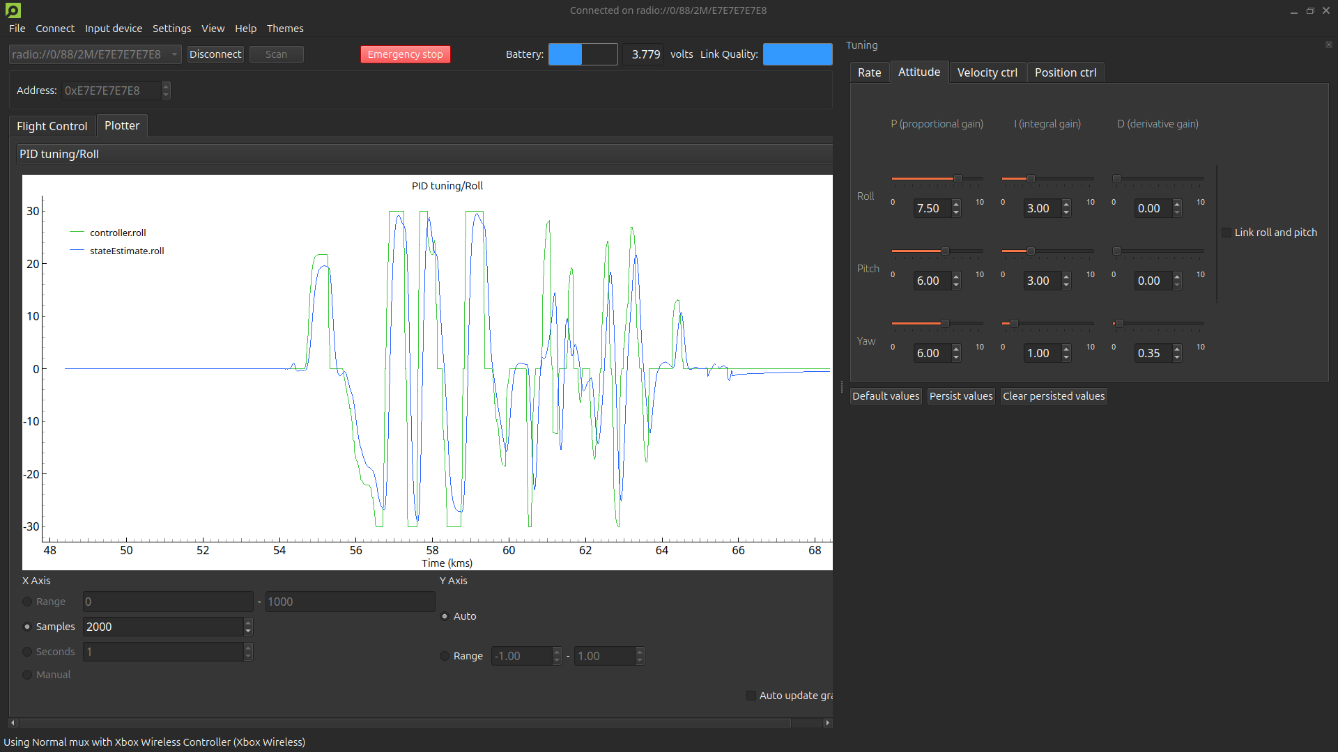
We are excited to announce the release of our new PID Tuning Guide! This guide is designed to help users understand and apply the basics of PID tuning within our ecosystem, making it easier to achieve stable and responsive flight for your Crazyflie. This guide is particularly useful if you’ve modified your drone, such as adding expansion decks or changing its motor and/or propeller configuration. While our default tuning is designed to work in a wide range of situations and configurations, fine-tuning your PID settings can enhance performance for your specific setup and flight profile.
Interface with tuning toolbox and plotter displaying the roll angle setpoint and the roll angle state estimate.
What’s in the guide?
The guide covers essential topics, including:
Fundamental PID Concepts: Understand the role of Proportional, Integral, and Derivative parameters in controlling your Crazyflie’s movements.
Step-by-Step Instructions: Learn how to set up your software, and use cfclient for tuning.
Practical Tuning Tips: Get insights on adjusting PID gains, using the tuning toolbox, and conducting safe manual flight tests.
Why this guide is useful
Even though this guide focuses on the basics, it provides a solid foundation for anyone new to PID tuning. Whether you’re using the Crazyflie 2.1, Crazyflie 2.0, or a custom-built quadcopter with the Crazyflie Bolt, this guide will help you:
Understand how PID controllers work and why they are important.
Use the cfclient for PID tuning within our ecosystem.
Safety first
We prioritize safety in our guide. Always secure your quadcopter in a safe environment, use protective gear, and configure an emergency stop on your controller to ensure a safe tuning process.
Get started with PID tuning today!
Ready to improve your quadcopter’s flight performance? Check out our PID Tuning Guide and start tuning.