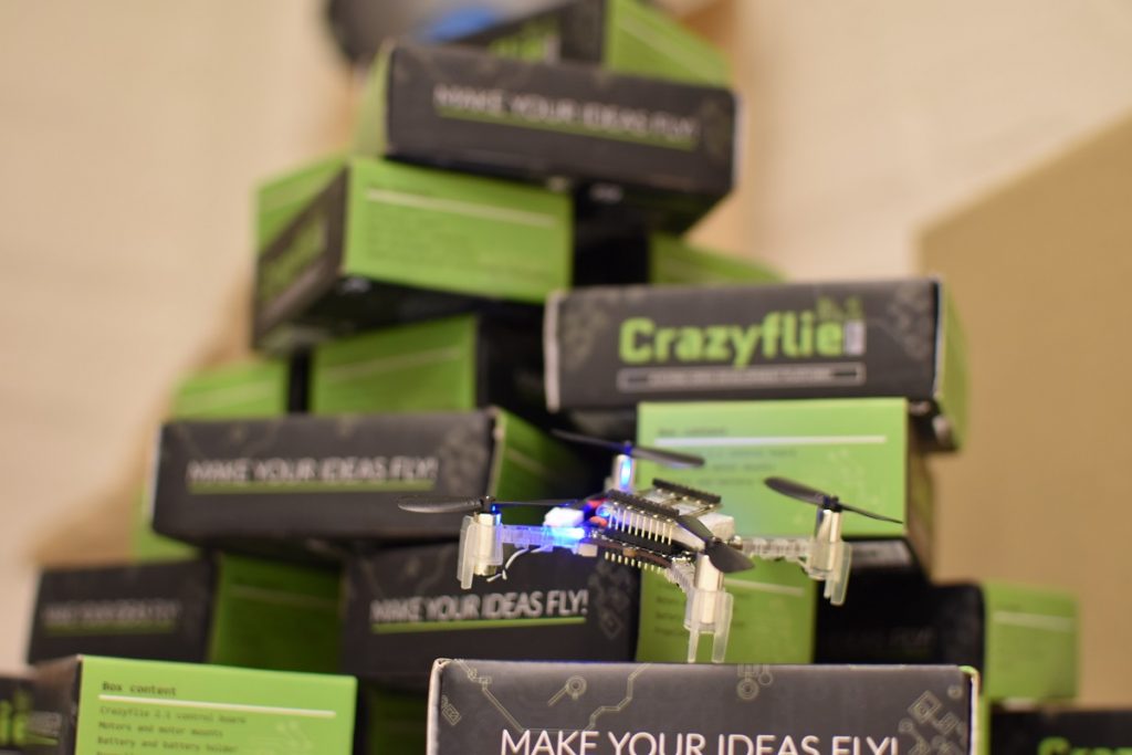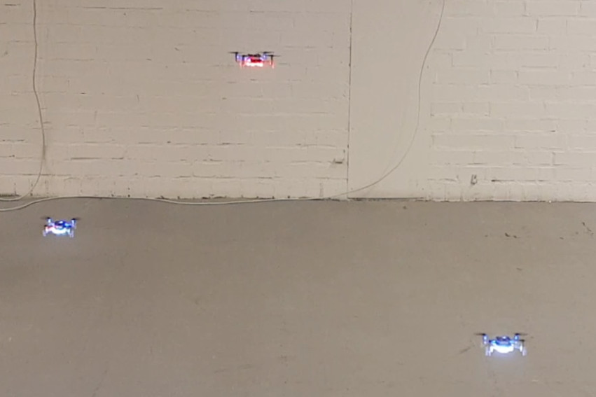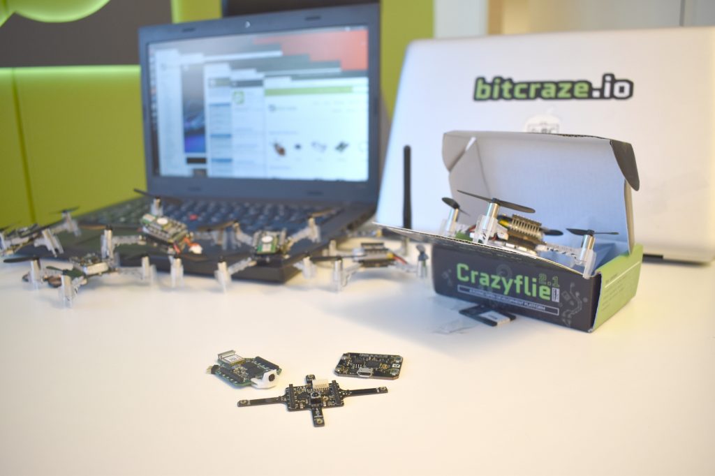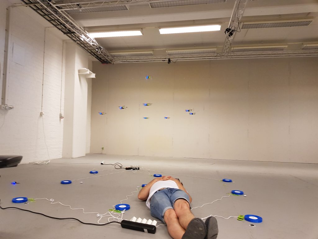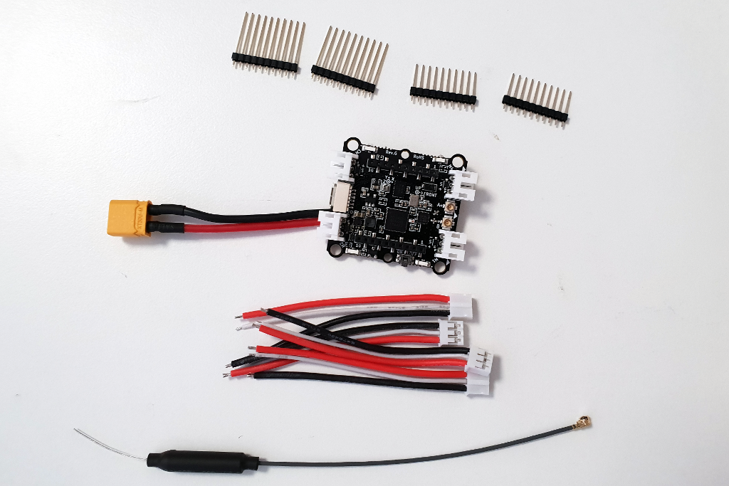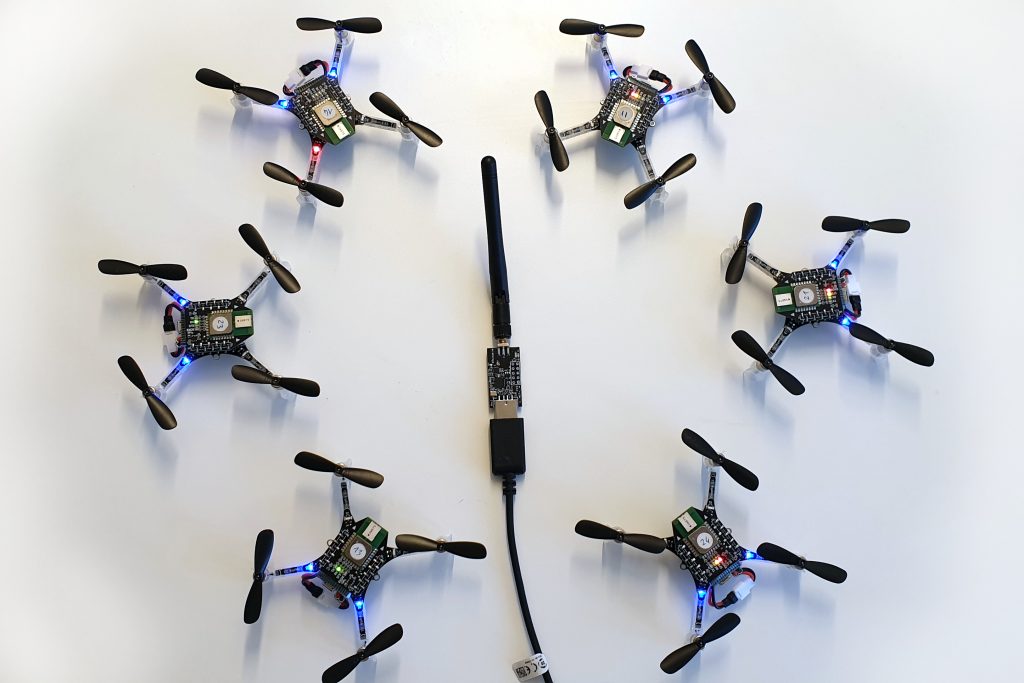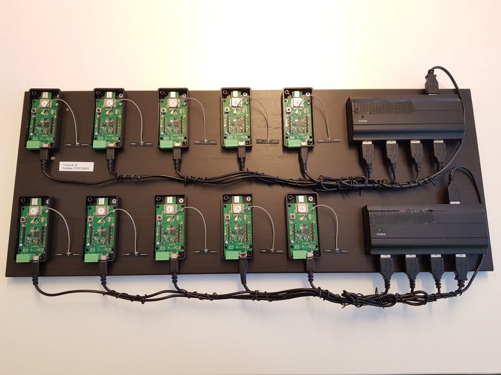
The Crazyflie 2.0 has been flyable in MoCap systems such as Qualisys, Vicon or Optitrack for quite a while thanks to the Crazyswarm project. For the MoCap systems to be able to track the Crazyflie it needs to be fitted with reflective markers. These can be attached on e.g the motor mounts which in some cases might be the best solution, however we also liked the idea of creating a deck where the markers easily can be attached and in many, repeatable configurations, that is why we created the Mocap deck. This deck is now soon to be released but before we start manufacturing it would be great to get some feedback.
The deck has M3 sized holes which is spaced on a 5mm grid. The deck also has footprints for two optional push buttons that can be used to e.g. trigger a take-off or start of a demo. And as the battery holder deck, which has no electronics, so this can be mounted upside down for better fitting of the markers, if the buttons aren’t mounted of course.
We are collaborating with Qualisys, also based in Sweden (in Gothenburg), to make the Crazyflie more moCap friendly and make it easy to use together with the Qualisys system as well as other mocap systems. Qualisys will provide the markers for the moCap deck.
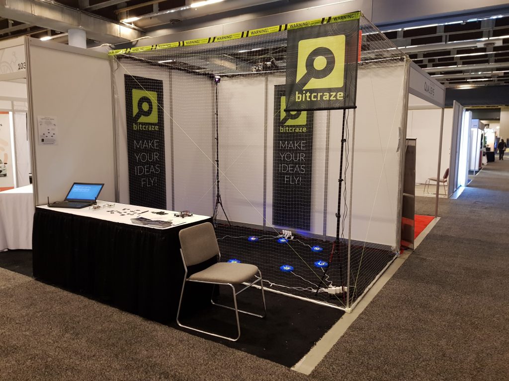
Qualisys and Bitcraze are exhibiting together at IROS in Madrid where we will show some awesome demos with a moCap system as well as other position technologies and we are also hoping to fly a Crazyswarm. We will publish more information when we get closer to the conference.
A lot of awesome things have been going on at Bitcraze during the last couple of months (like TDoA3, Swarm shows and a new front page), but on the logistics side we’ve been struggling. Like we wrote a couple of weeks ago we’ve been having huge issues with out 3rd party warehouse supplier. Unfortunately the issues have continued and we’ve been working hard on patching things together to get orders to our customers as soon as possible, but it’s not a sustainable situation and some of our customers have unfortunately had to wait too long for their orders to arrive.
So a couple of weeks ago we took the decision to move handling of the E-store from the 3rd party in Hong Kong to our office in Sweden. This will initially mean more work for us, but we feel that it’s something we need to do in order to keep the level of service we want to give our customers. So for the time being orders will be shipped from our office in Sweden.
So what does this mean in practice? Except for things hopefully working much more smoothly there won’t be any noticeable change for non-EU customers. However for EU customers there’s a big improvement: previously our EU customers had to import the products into the EU where the orders where subject to VAT and import duties. With the E-store moved to Sweden these orders are now subject to Swedish VAT (25%) directly on the order and customers will not have to import the goods so no additional VAT or duties are added upon receiving the order. Since this makes things easier and faster for our EU customers we’re really happy about this. Note that for customers with valid EU VAT numbers the VAT can be deducted directly in the E-store, you can either enter your VAT number directly in the cart or in your account if you have created one.
We’re doing our best to sort out the new situation and if there’s any issues along the way please let us know so we can work on fixing them.
We have now worked a few weeks on the new TDoA 3 mode for the Loco Positioning System. We are happy with the results so far and think we managed to do what we aimed for: removing the single point of failure in anchor 0 and supporting many anchors as well as larger spaces.
We finished off last week by setting up a system with 20 anchors covering two rooms down in the lunch area of the office. We managed to fly a scripted autonomous flight between two rooms.
Work so far on the anchors
Messages from the anchors are now transmitted at random times, which removes the dependency on anchor 0 that used to act as a master that all other anchors were synchronized to. The drawback is that we get problems with collisions when two anchors happens to transmit at the same time. Experiments showed that at 400 packets/s (system rate) we ended up at a packet loss of around 15% and 340 TDoA measurements/s sent to the kalman filter for position estimation. We figured that this was acceptable level and added an algorithm in the anchors that reduces the transmission rate based on the number of anchors around them. If more anchors are added to a room they all reduce their transmission rate to target 400 packets/s in total system rate.
The anchors continuously keeps track of the clock drift of all other anchors by listening to the messages that are transmitted. We know that clocks do not change frequency suddenly and can use this fact to filter the clock correction to reduce noise in the data. Outliers are detected and removed and the resulting correction is low pass filtered. We have done some experiments on using this information and compare it to the time stamp of a received message to detect if the time stamp is corrupt or not, but this idea requires more work.
One interesting feature of the anchors is the limited CPU power that is available. The strategy we have chosen to handle this fact has been to create an algorithm that is efficient when handling messages. A timer based maintenance algorithm (@1 Hz) examines the received data and makes demissions on which anchors to include in the messages in the future as well as purges old data.
The Crazyflie
The implementation in the Crazyflie is fairly straight forward. The biggest change to TDoA 2 is that we now can handle a dynamic number of anchors and have to chose what data to store and what to discard. We have also extracted the actual TDoA algorithm into a module to separate it from the TDoA 3 protocol. The clock correction filtering algorithm from the anchors has also been implemented in the Crazyflie.
An experimental module test has been added where the TDoA module is built and run on a PC using data recorded from a sniffer. We get repeatability as well as better tools for debugging and this is something that we should explore further.
Work remaining
The estimated position in the Crazyflie is still more noisy than in TDoA 2 and we would like to improve it to at least the same level. We see that we have outliers in the TDoA measurements that makes the Crazyflie go off in a random direction from time to time, we believe it should be possible to get rid of most of these.
The code is fairly hackish and there are no structured unit or module tests to verify functionality. So far the work has been in an exploratory phase but we are getting closer to a set of algorithms that we are happy with and that are worth testing.
We have not done any work on the client side, that is support for visualizing and configuring the system. This is a substantial amount of work and we will not officially release TDoA 3 until this is finished.
How to try it out
If you are interested in trying TDoA 3 out your self, it is all available on github. There are no hardware changes and if you have a Loco Positioning system it should work just fine. There is a short description on the wiki of how to compile and configure the system. The anchor supports both TDoA 2 and TDoA 3 through configuration while the Crazyflie has to be recompiled to change between the two. The support in the client is limited but will basically handle anchors 0 – 7.
Things are moving fast here at Bitcraze and we have lots of exciting things going on. So it’s time to grow the team and try to add one or two new team-members to increase the tempo and bring more awesome products to our customers. The normal case might be that you would post a job ad describing what kind of skill-set potential new members should have, but we would like to try something different. So today we added a jobs page describing a bit about how we work and what we do. Our goal is to give a picture of what it’s like to work at Bitcraze and try to find individuals who like what we do and how we work. If you would be interested in joining the team let us know on jobs@bitcraze.io who you are, what you like and how you think you could contribute.
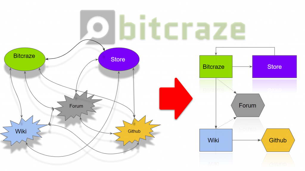
Returning visitors of our website might have noticed that we recently released a new and fresh design of our website’s front page.
The goal has been to make a front page that better reflects Bitcraze and what we do, so together with the updated design and new cool images (credit to USC) we have also added two new sections to the front page. First off we have extended the blog post section to show the three latest blog posts instead of just the latest one. Different users have different interests so by showing a bit wider range of blog topics the hope is that even more people will discover our blog and start following it. Our blog is a big part of how we communicate to the outer world so by adding a whole new section for the blog giving it more room on the front page feels exciting.
The testimonials section is the second part that we have added to the new front page. Here we are finally taking the opportunity to show some of the amazing work our community members have been doing using our Crazyflie. Each testimonial consist of a guest blog post that people from our community have contributed. It is pretty cool to show how researchers around the world are basing their projects on our products. If it’s by adding wheels to the drone or making LED lit swarms we are always happy to promote and show how the community are using our Crazyflie.
Next step
Our website is under constant improvement and the grand master plan for the near future is to update the content and design of the different portals and clean up the website in general. If you have any suggestions on what kind of content you would like to see in the portals or otherwise please send us feedback. As I mentioned in the beginning of the blog post, the new beautiful open shutter swarming photos we use on the front page is contributed to us by the researchers at USC. If you have any cool photos of the Crazyflie we would be more than happy to use them.
First of all we are happy to announce that (almost) all products have been stocked in the new warehouse and are now shipping! The last orders that were on hold are on their way out and new orders placed in the store will now be shipped again within a few days.
We released the TDoA mode, a.k.a. swarm mode of the Loco Positioning System back in January. TDoA supports positioning of many Crazyflies simultaneously which makes it possible to fly a swarm of Crazyflies with the LPS system. The release in January was actually the second iteration of the TDoA implementation (the first iteration was never publicly released) and it is also known as TDoA 2.
TDoA 2 works well but there are a couple of snags that we would like to fix and we have now started the work on the next iteration, TDoA 3.
Single point of failure
TDoA 2 is based on a fixed transmission schedule with time slots when each anchor transmits its ranging packet. All anchors listen to anchor 0 and use the reception of a packet from anchor 0 to figure out when to transmit. The problem with this solution is that if anchor 0 stops transmitting for some reason the full system will stop transmitting positioning information. This is clearly a property that would be nice to get rid of.
Limited number of anchors
The packets in the TDoA 2 protocol have 8 slots for anchor data that are implicitly addressed through the position in the packet. First slot is anchor 0, second slot anchor 1 and so on. This setup is easy to use but creates an upper limit of 8 anchors in the system.
The maximum radio reach of an anchor depends mainly on the transmitted power and the environment. This distance, in combination with a maximum of 8 anchors and that all anchors must be in range of anchor 0, sets an upper limit of the volume that an LPS system can cover, basically one large room. When we designed TDoA 2 we were happy to be able to support a swarm of Crazyflies and did not really bother too much about the covered volume. We get more and more questions about larger areas and more anchors though and it would be nice to have a positioning system that could be expanded.
The solution – maybe…
What we want to do in TDoA 3 is to transmit packets at random times and add functionality to handle the collisions and packet loss that will happen in a system like this. The idea is that the even if some data is lost, the receiving side will get enough packets to be able to calculate the distance to other anchors or a position as needed. By removing the time slots and synchronization to anchor 0, we get rid of the single point of failure.
In the TDoA 3 protocol, we have added explicit ids to the anchor data, and thus removed the implicit addressing of anchors. We have 8 bits for anchor ids and the system will handle 256 anchors for sure. We do think that it will be possible to design larger systems though by reusing ids and making sure that the radio ranges of anchors with the same ids do not overlap.
The UWB radios have a nice property that makes this a bit easier to handle collisions than one might first think, if they receive two packets at the same time, they will most likely “pick” one of the packets and discard the other. The drawback is that it is likely that the receive time of the packet will be less accurate. We are not completely sure it will be possible to detect and handle the added noise in the time stamps but we have good hope!
The current state of the project
Last week we did a proof of concept hack when we modified the old TDoA 2 implementation to transmit at random times, as well as minor modifications to handle random receive order of packets. It all worked out beautifully and we could fly a short sequence in the office with the new mode. The estimated position was a bit more shaky which is not surprising, considering that the receive times are more noisy.
We have just started with the real deal. We have designed a draft spec of the protocol and have also started to implement the new protocol on top of the old TDoA2 algorithms in the anchors and the Crazyflie to get started. Next steps will be to introduce random transmission times, dynamic anchor management and better error handling. The TDoA 3 implementation will exist in parallel with the current TDoA2 implementation and should not interfere.
If you want to contribute, are interested in what we do or have some input, please comment this blog post or contact us in any other way.
Something we seldom write about on the blog is production and supply chain. It’s a big part of what we do, both in time and business wise. Even though we spend most of our time on firmware/software we’re actually only selling hardware. So this blog-post is about how we’ve set this up and the problems we’ve been facing the last month due to our 3rd party warehouse moving to a new location.
The current set-up
Currently we’re using Seeedstudio for our manufacturing. They do varying batch sizes, but most of the batches we produce are between 300 and 2000 units. We’ve been experimenting a bit with varying size of batches, too large and you tie up too much funds in stock while with smaller batches you spend most of you’re time tending to manufacturing. Another issue with large batches are things like battery shelve life and changing market (i.e suddenly some parts are EOL or have been replaced when it’s time for the next batch). Finding a good level for different products depending on production cost, complexity and shelf-life is tricky.
After production the goods are moved to a number of warehouses. Part of the goods are warehoused at Seeedstudio, part of them are sent to our 3rd party warehouse in Hong Kong serviced by Shipwire and a small amount is sent to our office for testing/development/customers. The products in Seeedstudio’s warehouses services a number of distributors though their wholesale channels as well as end-users though their Bazaar. We service our E-store though Shipwire in Hong Kong and a few customer though our Swedish office.
Scaling up
Since the end of last year we’ve seen an increase of sales, which we are of course really happy about! More sales will mean more resources for development which translates into more awesome products and features for everyone. The problem is that it takes time to scale up the supply chain on the back. Today we have have 27 SKUs and 7 bundle SKUs “virtually” made out of combining products into bundles. Out the 27 SKUs we control the manufacturing of 17 SKUs (like PCBs and plastic parts) and 5 SKUs are things we buy (like the USB-cable). Typically the lead time for simpler products is 1 month and more complex products 2 months, with an additional lead-time of at least a week to reach our Hong Kong warehouse and become available in the E-store. Creating bundles by “virtually” tying together a number of products is great since it gives us more flexibility but if one of the bundled SKUs is out of stock the bundle will also be our of stock.
Controlling this complex situation while scaling up for larger sales has proved challenging, also when everything works as expected (see below). Most of our customers have gotten their things in time, but we’ve had to put a lot of hours into juggling products around between warehouses to make it happen.
Warehouse issues
Back in February we were notified by Shipwire that they would be moving the operation to a new warehouse in Shenzhen/Hong Kong. The timeline that was communicated was that the inventory would be offline 3rd – 6th of April. This might seem optimistic for a warehouse that is about 10 000 m2, but since they have a large amount of warehouses around the globe we assumed they would pull this off. Unfortunately this wasn’t the case, a number of factors played in to delay the move. Since the first week of delays the expected timeline has been “next week”, which unfortunately hasn’t held. Finally we’re at a point where our old inventory has been moved into the new warehouse and is available. The next problem we’re facing is getting our incoming goods into the inventory, which is currently expected to be finished by the end of this week. To say the least we’re unhappy about this situation, but unfortunately we have had very little control. We don’t have a large number of products available in any other warehouse so we haven’t been able to “switch over” to another solution. We’ve done our best to keep the effected customers updated on the situation and calling support every day to get an update.
Moving forward
We’re a small team of 5 people and we’ve always been most focused on product development. It’s what we like to do and it’s what we’re best at. So an easy way forward would be to pay someone else to handle all of the above. Unfortunately this has proven to be tricky for us. Basically handing over everything that generates revenue for our company to someone else is a huge risk, to say the least. So we’ve realized that this has to be a central part of what we do, just like development. This was the main reason for starting our own E-store last year and it’s something we’re continuously working on improving.
Moving forward the overall goal is to minimize the work spent on production and stock management while making sure to not run out of stock or tie up all our funds in stock. We think that one key to this is being proactive instead of reactive. So we have integrated this into our daily work just as much as development. Next to the “development” board with stories/tasks we have an even bigger kanban board with production/logistics/warehouses and it’s something that is constantly part of the planning/status meetings. We’ve also been gearing up for producing batches of popular products more often and increasing the batch sizes to meet the increased demand and to lower the risk of being out of stock. The last part is an internal system we’ve been developing during the last couple of years that keeps track of stock, production, customer shipments and stats in general. More on this in a future blog-post!
The Bitcraze Virtual Machine is designed as a quick and isolated way to start development with Crazyflie and other bitcraze projects.
The current VM is starting to get very old, even though we keep it updated it is based on XUbuntu LTS 14.04. This month Ubuntu LTS 18.04 is being release which is a good reason to upgrade the VM!
The main update will then to switch from XUbuntu 14.04 to XUbuntu 18.04. There is a couple more things that we are looking at updating:
Updating Eclipse and CDT to the latest version Oxygen.3a
Fixing Eclipse code completion and hinting configuration
Pre-configuring eclipse with gnu-mcu-eclipse to make it easier to flash and debug Crazyflie.
Fixing the virtual machine Crazyradio communication bugs
We are writing this blog post as a request for comment:
Is there anything else that you would like to add/remove in the new virtual machine?
Anything we could do to make it easier to start developing for Crazyflie?
The virtual machine is generated automatically using packer and VirtualBox, the code is hosted on GitHub. If you want to help making the VM or want functionality to be added to it do not hesitate to open a ticket in the bug tracker.
It’s time for an update on the Multi-ranger deck (see previous updates here: 1, 2, 3). Back in February/March we were just about to start the production of the Multi-ranger deck when the new VL51L1 ToF sensor from ST became available. Among the interesting features for the new sensor is increased range and ROI (region of interest) settings. We felt that the improvement was enough to consider using the new sensor for the Multi-ranger so we got some sensors and started testing.
Point cloud
We’ve made a little example where you can control the Crazyflie with a keyboard (using velocity mode) that records estimated position, body attitude and all the distances (down/up, left/right, front/back) from the ToF sensors. We then did some post-processing of the log data and plotted it using pyntcloud, you can see the results in the point cloud. There are still lots of possible improvements (like taking body attitude into consideration) to be made on the script, but once we’ve cleaned it up a bit we’ll publish it on GitHub so others can play around with it. Note that in the plot the blue points are up/down sensors (i.e Crazyflie movement) and the red points are the side sensors (front/back/left/right).
The room that was mapped
So far we’re happy with the results. We feel that the increased range and new features enables users to work on more interesting problems with the deck, so we’ve decided to switch our the sensors and go to production with the new one. Right now we’re running a 0-series of 10 units using the real production manufacturing fixture (for the standing PCBs with sensors) as well as the production test rig. Our best estimate for when the deck will become available for purchase is some time during the summer. Below is a picture of the latest prototype. We’ll make sure to keep you updated on the progress!
Warehouse issues
On an additional note we’re having some issues with our warehouse provider which ships out orders from our E-store. In the beginning of the month the provider hade scheduled a move of the warehouse to a new physical location which would delay handling of orders for max a week. Unfortunately the move, which should have been finished mid last week, is still in progress which means we can’t ship out any orders for the moment. We’re working hard on trying to work this out with the provider.
I’ve spent the last 5 years of my career at Microsoft on the team responsible for HoloLens and Windows Mixed Reality VR headsets. Typically, augmented reality applications deal with creating and manipulating digital content in the context of real-world surroundings. I thought it’d be interesting to explore some applications of using an augmented reality device to manipulate and control physical objects and have them interact with the real world and/or digital content.
Phase 1: Gesture Input
The HoloLens SDK has APIs for consuming hand gestures as input. For the first phase of this project, I modified the existing Windows UAP/UWP client to handle these gestures and convert them to CRTP setpoints. I used the “manipulation gesture” which provides offsets in three dimensions for a tap-and-drag gesture, from the point in space where the initial tap occurred. These three degrees of freedom are mapped to thrust, pitch and roll.
For the curious, there’s an article on my website with details about the implementation and source code. Here’s a YouTube video where I explain the concept and show a couple of quick demos.
As you can see in the first demo in the video, this works but isn’t entirely useful or practical. The HoloLens accounts for head movements (otherwise moving the head to the left would produce the same offset as moving the hand to the right, requiring the user to keep his or her head very still) but the user must still take care to keep the hand in the field of view of the device’s cameras. Once the gesture is released (or the hand goes out of view) the failsafe engages and the Crazyflie drops to the ground. And of course, lack of yaw control cripples the ability to control the Crazyflie.
Phase 2: Position Hold
Adding a flow deck makes for a more compelling user experience, as seen in the second demo in the video above. The Crazyflie uses the sensors on the flow deck to hold its position. With this functionality, the user is free to move about the room and make shorter “adjustment” hand gestures, instead of needing to hold very still. In this mode, the gesture’s degrees of freedom map to an x/y velocity and a vertical offset from the current z-depth.
This is a step in the right direction, but still has limitations. The HoloLens doesn’t know where it is in space relative to the Crazyflie. A gesture in the y axis relative to the device will always result in a movement in the y direction of the Crazyflie, which begins to feel unnatural if the user moves around. Ideally, gestures would cause the crazyflie to move in the same direction relative to the user, not relative to the ‘front’ of the Crazyflie. Also, there’s still no control over yaw.
The flow deck has some limitation as well: The z-range only goes to 2 meters with any accuracy. The flow sensor (for lateral stabilization) has a strong dependency on the patterns on the floor below. A flow sensor is a camera that relies on measuring pixel deltas from frame to frame, so if the floor is blank or has a repeating pattern, it can be difficult to hold position properly.
Despite these limitations, using hand gestures to control the Crazyflie with a flow deck installed as actually quite fun and surprisingly easy.
Phase 3 and Beyond: Future Work & Ideas
I’m currently working on some new features that I hope will open the door for more interesting applications. All of what follows is a work in progress, and not yet implemented or functional. Dream with me!
Shared Coordinate System
The next phase (currently a work in progress) is to get the HoloLens and the Crazyflie into a shared coordinate system. Having spatial awareness between the HoloLens and the Crazyflie opens up some very exciting scenarios:
The orientation problem could be improved: transforms could be applied to gestures to cause the Crazyflie to respond to commands in the user’s frame of reference (so ‘pushing’ away from one’s self would cause the Crazyflie to fly away from the user, instead of whatever direction is ‘forward’ to the Crazyflie’s perspective).
A ‘follow me’ mode, where the crazyflie autonomously follows behind a user as he or she moves throughout the space.
Ability to walk around and manually set waypoints by selecting points of interest in the environment.
The Loco Positioning System is a natural fit here. A setup step (where a spatial anchor or similar is established at same physical position and orientation as the LPS origin) and a simple transform for scale and orientation (HoloLens and the Crazyflie define X,Y,Z differently) would allow the HoloLens and Crazyflie to operate in a shared coordinate system. One could also use the webcam on the HoloLens along with computer vision techniques to track the Crazyflie, but that would require constant line of sight from the HoloLens to the Crazyflie.
Obstacle Detection/Avoidance
The next step after establishing a shared coordinate system is to use the HoloLens for obstacle detection and avoidance. The HoloLens has the ability to map surfaces in real time and position itself in that map (SLAM). Logic could be added to the HoloLens to consume this surface map and adjust pathing/setpoints to avoid these obstacles without reducing the overall compute/power budget of the Crazyflie itself.
Swarm Control and Manipulation
As a simple extension of the shared coordinate system (and what Bitcraze has been doing with TDoA and swarming lately) the HoloLens could be used to manipulate individual Crazyflies within a swarm through raycasting (the same technique used to gaze at, select and move specific holograms in the digital domain). Or perhaps a swarm could be controlled to move out of the way as a user passes through the swarm, and return to formation afterward.
Augmenting with Digital Content
All scenarios discussed thus far have dealt with using the HoloLens as an input and localization device, but its primary job is to project digital content into the real world. I can think of applications such as:
Games
Flying around through a digital obstacle course
First person shooter or space invaders type game (Crazyflie moves around to avoid user or fire rendered laser pulses at user, etc)
Diagnostic/development tools
Overlaying some diagnostic information (such as battery life) above the Crazyflie (or each Crazyflie in a swarm)
Set or visualize/verify the position of the LPS nodes in space
Visualize the position of the Crazyflie as reported by LPS, to observe error or drift in real time
Conclusion
There’s no shortage of interesting applications related to blending augmented reality with the Crazyflie, but there’s quite a bit of work ahead to get there. Keep an eye on the Bitcraze blog or the forums for updates and news on this effort.
I’d love to hear what ideas you have for combining augmented reality devices with physical devices like the Crazyflie. Leave a comment with thoughts, suggestions, or any other relevant work!