Blog

Historically our server environment has been pretty basic and manual. The main focus in the company has been to build awesome copters, so managing the infrastructure for delivering services such as web, forum and wiki has been low priority. The services has been up and running most of the time, which after all is the most important property, but making changes has required a fair amount of manual work and has also been associated with some unknowns and risks. When you don’t feel safe, or if the procedure is not sufficiently simple we have a tendency to avoid doing stuff. The end result has been that we have not updated our web as often as we would have liked.

During the summer we are trying to catch up and clean out some of the technical debt we have left behind – including the infrastructure for the web. In this post I will outline what we are doing.

Goals

So, we want to simplify updates to our web, but what does that mean to us?

  1. It should be dead simple to set up a development environment (or test environment) that has exactly the same behaviour as the production environment.
  2. We want to know that when we make a change in a development environment, the exact same change will go into production – without any surprises.
  3. After developing a new feature in your development environment, it should be ultra simple to deploy the change to production. In fact, it should be so simple that anyone can do it, and so predictable that it is boring.
  4. We want to make sure our backups are working. Too many people did not discover that their backup procedures were buggy until their server crashed and had to be restored.

We want to move towards Continuous Delivery for all our systems and development, and these goals would be baby steps in the right direction.

Implementation

We decided that the first step would be to fix our web site, wiki and forum. The web is based on WordPress, the wiki on DocuWiki and the forum on PhpBB and they are all running on apache with a mysql database server on a single VPS . We wanted to stay on the VPS for now but simplify the process from development to production. We picked my new favourite tool: Docker.

Docker

Docker is by far the coolest tool I have used the last couple of years. I think it fundamentally will change the way we use and manage development-, test- and production environments, not only for the web or backend systems, but probably also for embedded systems. For anyone that wants to move in the direction of continuous delivery, docker is a must to try out.

So, what is Docker? If you don’t know, take a look at https://www.docker.com/

The typical workflow when creating new functionality could be

  1. Make some changes to the codebase and commit the source code to your repository.
  2. Build and run automated test
  3. Build a docker image from the source code
  4. Deploy the image in a test environment and run more tests
  5. Deploy the image to production

Preferably steps 2 to 5 are automated and executed by a server.

In the docker world images are stored in a registry to be easily retrievable on any server for deployment. One part of the docker ecosystem is the public registry called Docker Hub where people can upload images for others to use. There are a lot of good stuff to use, especially the official images created by docker for standard applications such as Apache, MySql, PHP and so on. These images are a perfect staring point for your own images.  In the workflow above we would push the image in step 2 to the registry and pull it in step 3 and 4.

Private registry

It is possible to push your images to the public Docker Hub but our images will contain information that we don’t want to share such as code and SSL certificates, so we needed a private registry. You can pay for that service in the cloud, but we decided to go for our own private registry as a start.

There is an official docker image that contains a registry that we used. Your registry requires some configuration, and you could create your own image from the official image + configuration. But, then where do you store the image? Luckily it is possible to run the registry image and pass the configuration as parameters at start up. The command to start the registry ended up something like this:

docker run -d --name=registry -p ${privateInterfaceIp}:5000:5000 -v ${sslCertDir}:/go/src/github.com/docker/distribution/certs -v ${configDir}:/registry -v ${registryStoragePath}:/var/registry registry:2.0 /registry/conf.yml

The default docker configuration is to use https for communication so we give the registry the path to our ssl certificate, the path to a configuration file and finally somewhere to store the files in our file system. All these paths are mapped into the file system of the container with the -v switch.

The configuration file conf.yml is located in the configDir and the important parts are:

version: 0.1
log:
  level: debug
  fields:
    service: registry
    environment: development
storage:
    filesystem:
        rootdirectory: /var/registry
    maintenance:
        uploadpurging:
            enabled: false
http:
    addr: :5000
    secret: someSecretString
    debug:
        addr: localhost:5001
    tls:
        certificate: /go/src/github.com/docker/distribution/certs/my_cert.fullchain
        key: /go/src/github.com/docker/distribution/certs/my_cert.key

The file my_cert.fullchain must contain not only your public certificate, but also the full chain down to some trusted entity.

Note: this is a very basic setup. You probably want to make changes for production.

Code vs data

A nice property with docker is that it is easy to separate code from data, they should basically go into separate containers. When you add functionality to your system, you create a new image that you use to create a container from in production. These functional containers have a fairly short lifecycle, they only live until next deploy. To create a functional image, just build your image from some base image with the server you need and add your code on top of that. Simply put, your image will contain both your server and application code, for instance Apache + WordPress with our tweaks.

When it comes to data there are a number of ways to handle it with docker and I will not go into a discussion of pros and cons with different solutions. We decided to store data in the filesystem of data containers, and let those containers live for a long time in the production environment. The data containers are linked to the server containers to give them access to the data.

In our applications data comes in two flavors: SQL database data and files in the filesystem. The database containers are based on the official mysql images while filesystem data containers are based on the debian image.

Backups

To get the data our of the data containers for backups, all we have to do is to fire up another container and link it to the data container. Now you can use the new container to extract the data and copy it to a safe location.

docker run --rm --volumes-from web-data -v ${PWD}:/backup debian cp -r /var/www/html/wp-content/gallery /backup

will start a debian container and mount the volumes from the “web-data” data container in the filesystem, /var/www/html/wp-content/gallery in this case. We also mount the current directory on the /backup directory in the container. Finally we copy the files from /var/www/html/wp-content/gallery (in the data container) to /backup, so they will end up in our local filesystem. When the copy is done the container will die and automatically removed.

Creating data containers

We need data containers to run our servers in development and test. Since we don’t have enormous amounts of data for these applications we simply create them from the latest backup. This gives us two advantages; first we can develop and test on real data, and secondly we continuously test our backups.

Development and production

We want to have a development environment that is as close to the production environment as possible. Our solution is to run the development environment on the same image that is used to build the production image. The base image must contain everything needed except the application, in our case Apache and PHP with appropriate modules and extensions. Currently the docker file for the base image looks like

FROM php:5.6-apache
RUN a2enmod rewrite
# install the PHP extensions we need
RUN apt-get update && apt-get install -y libpng12-dev libjpeg-dev && rm -rf /var/lib/apt/lists/* \
	&& docker-php-ext-configure gd --with-png-dir=/usr --with-jpeg-dir=/usr \
	&& docker-php-ext-install gd
RUN docker-php-ext-install mysqli
RUN docker-php-ext-install exif
RUN docker-php-ext-install mbstring
RUN docker-php-ext-install gettext
RUN docker-php-ext-install sockets
RUN docker-php-ext-install zip
RUN echo "date.timezone = Europe/Berlin" > /usr/local/etc/php/php.ini
CMD ["apache2-foreground"]

An example will clarify the concept

Suppose we have the source code for our wiki in the “src/wiki” directory, then we can start a container on the development machine with

docker run --rm --volumes-from=wiki-data -v ${PWD}/src/wiki:/var/www/html -p 80:80 url.to.registry:5000/int-web-base:3

and the docker file used to build the production image contains

FROM url.to.registry:5000/int-web-base:3
COPY wiki/ /var/www/html/
CMD ["apache2-foreground"]

For development the source files in src/wiki are mounted in the container and can be edited with your favourite editor, while in production they are copied to the image. In both cases the environment around the application is identical.

If we tagged the production image “url.to.registry:5000/int-web:3” we would run it with

docker run --rm --volumes-from=wiki-data -p 80:80 url.to.registry:5000/int-web:3

WordPress

WordPress is an old beast and some of the code (in my opinion) is pretty nasty. My guess is that it is mostly due to legacy and compatibility reasons. Any how this is something that has to be managed when working with it.

In a typical WP site, only a small portion of the codebase is site-specific, that is the theme. The rest of the code is WP itself and plugins. We only wanted to store the theme in the code repo and pull the rest in at build time. I found out that there are indeed other people that had the same problem and that they use the composer to do this (https://roots.io/using-composer-with-wordpress/). Nice solution! Now the code is managed.

Next problem is the data in the file system. WP writes files to some dirs in the wp-content directory, side by side with source code dirs and code pulled in with composer. There is no way of configuring these paths, but docker to the rescue! We simply created a docker data container with volumes exposed at the appropriate paths and mount it on the functional container. wp-content/gallery and wp-content/uploads must be writable and WP writes files here.

.
|-- Dockerfile
|-- composer.json
|-- composer.lock
|-- composer.phar
|-- index.php
|-- vendor
|-- wp
|-- wp-config.php
`-- wp-content
    |-- gallery
    |-- ngg_styles
    |-- plugins
    |-- themes
        |-- bitcraze
    `-- uploads

To create the data container for the filesystem and populate with data from a tar gz

docker create --name=web-data -v /var/www/html/wp-content/uploads -v /var/www/html/wp-content/gallery debian /bin/true
docker run --rm --volumes-from=web-data -v ${PWD}/dump:/dump debian tar -zxvf /dump/wp-content.tar.gz -C /var/www/html
docker run --rm --volumes-from=web-data debian chown -R www-data:www-data /var/www/html/wp-content/uploads /var/www/html/wp-content/gallery

To create the database container and populate it with data from a sql file

docker run -d --name web-db -e MYSQL_ROOT_PASSWORD=ourSecretPassword -e MYSQL_DATABASE=wordpress mysql
docker run -it --link web-db:mysql -v ${PWD}/dump:/dump --rm mysql sh -c 'exec mysql -h"$MYSQL_PORT_3306_TCP_ADDR" -P"$MYSQL_PORT_3306_TCP_PORT" -uroot -p"$MYSQL_ENV_MYSQL_ROOT_PASSWORD" --database="$MYSQL_ENV_MYSQL_DATABASE" < /dump/db-dump.sql'

Note that the wp-config.php file goes into the root in this setup.

Now we can start it all with

docker run --rm --volume=${PWD}/src/:/var/www/html/ --volumes-from=web-data --link=web-db:mysql -p "80:80" url.to.registry:5000/int-web-base:3

Wiki

DocuWiki is a bit more configurable and all wiki data could easily be moved to a separate directory (I used /var/wiki) by setting

$conf['savedir'] = '/var/wiki/data';

in conf/local.php. User data is moved by adding to inc/preload.php

$config_cascade['plainauth.users']['default'] = '/var/wiki/users/users.auth.php';
$config_cascade['acl']['default'] = '/var/wiki/users/acl.auth.php';

Create the data container

docker create --name wiki-data -v /var/wiki debian /bin/true

When data has been copied to the data container, start the server with

docker run --rm --volumes-from=wiki-data -v ${PWD}/src/wiki:/var/www/html -p 80:80 url.to.registry:5000/int-web-base:3

Forum

PhpBB did not hold any surprises. Directories that needed to be mapped to the data filesystem container are cache, files and store. Database container created in a similar way as for wordpress.

Reverse proxy

The three web applications are running on separate servers and to collect the traffic and terminate the https layer, we use a reverse proxy. The proxy is also built as a docker image, but I will not describe that here.

More interesting is how to start all docker containers and link them together. The simplest way is to use docker-compose and that is what we do. The docker-compose file we ended up with contains

proxy:
  image: url.to.registry:5000/int-proxy:2
  links:
    - web
    - wiki
    - forum
  ports:
    - "192.168.100.1:80:80"
    - "192.168.100.1:443:443"
  restart: always

web:
  image: url.to.registry:5000/int-web:3
  volumes_from:
    - web-data
  external_links:
    - web-db:mysql
  restart: always

wiki:
  image: url.to.registry:5000/int-wiki:1
  volumes_from:
    - wiki-data
  restart: always

forum:
  image: url.to.registry:5000/int-forum:1
  volumes_from:
    - forum-data
  external_links:
    - forum-db:mysql
  restart: always

To start them all simply

docker-compose up -d

Conclusions

All this work and the result for the end user is – TA-DA – exactly the same site! Hopefully we will update our web apps more often in the future, with full confidence that we are in control all the time. We will be happier Bitcraze developers, and after all that is really important.

During the design-phase of the Crazyflie 2.0 products last year, we sat down and had a long discussion about testing. In order to make sure things runs smoothly, it’s best to make sure that the hardware you’re designing can be tested properly in manufacturing. It could be as simple as adding a few test-points or a bit more complicated like making sure the product can run self-tests to cover some of the testing. There’s also other factors that count, such as the time it takes to test one unit. The better the tests are the less hassle you will get down the line and the happier your customers will be. The cost of finding a faulty board during production is very low, while finding faulty units in the field can be a costly process.

When it comes to the Crazyflie 2.0 we tried to think all of this though during the design-phase, walking though the schematic and making sure that everything could be tested properly in manufacturing. Since the new design is more complex then the old one, we also ended up with a test procedure with more steps and more things that could potentially go wrong. So we felt we needed some way to keep track of the products all the way from the production, to faulty units we might get from customers. Figuring out how faulty units might get passed the testing is crucial for improving it. But in order to acheieve this you need some way to track each board, thankfully for us this was already solved.

Both the Crazyflie 2.0 and all the decks fitted with a 1-wire memory have a unique identifier, a serial number. So these can easily be used for tractability. But without any information to trace it not very useful. So we built a simple framework for reporting as all of the test data back to our servers where we could easily look up what was happening. Here’s a screenshot of what it looks like for a tested Crazyflie 2.0 (1-wire memory products look similar):

cf2_testing

So what’s all the information? Well, here’s a quick rundown:

  • Run list: Each test that involves the serial is listed, so it’s easy to select which one you want information about
  • golden_sample: Serial of the golden sample unit
  • power and power_d: The measured power and power deviation from the golden sample
  • freq and freq_d: The measured frequency and frequency deviation from the golden sample
  • Tests: The framework allows for a number of tests to be defined, the result of each test is reported and if the test fails it’s possible to see in which step this happened
  • Console output: For the Crazyflie 2.0 there’s a special case of being able to see the console output when the unit is started

There’s of course a lot of other nifty features with having this setup, like getting production updates in real-time and being able to look at lots of statistics. All in all we’re pretty happy with the system, but there’s still lots of things to be added. Oh, and if anyone is wondering what happens if the internet connection is lost: It’s all saved locally as well (and uploaded when the connection is recovered). Plan for the worst and hope for the best :-)

If you’re interested in seeing what some of the rigs looks like, then have a look at this old post with some pictures from when we started up the Crazyflie 2.0 manufacturing.


Continuing from last Monday post where the hardware wiring part was discussed we now move on to the software side. The brushed motors are controlled with a normal PWM  where the duty cycle will adjust how much power goes into the motors. A brushless motor on the other hand needs more complicated controlling and uses it’s own micro-controller to handle this. These brushless motor controllers (BLMC or Brushless ESC) comes in many flavors and sizes but what is pretty common is how they are interfaced/controlled. This is inherited from how R/C receivers are controlling servos and how the receiver gets updates from the transmitter. This is a PWM where the width of the high pulse define the duty cycle. 1ms equals min and 2ms equals max and this is repeated every 20ms, thus giving an update rate of 50Hz.ServoPwm

This way of interfacing the BLMC is currently the most common way but interfacing with I2C, CAN, etc is getting more common.

To generate the servo PWM on the Crazyflie we have just reconfigured the timer a bit using a conversion macro so that setting the motor ratio of zero will result in a 1ms high pulse and setting it to max (uint16) will result in a 2ms pulse. The period time can be set with the BLMC_PERIOD define in motors.h. The standard period time of 20ms is actually a big drawback as it adds a latency from when a new output is calculated to when it is actually set. Therefore many motor controllers allow to shrink this period down to 2.5ms (400Hz) which result in lower latency and better flight stability.

Brushless prototype board

First you need to put together the brushless prototype board from the last post. The output will be generated on the pins marked BLMC 1,2,3,4 which should be connected in the same position an rotational direction as the brushed M1, M2, M3, M4 respectively. The output signal will be 0v – 3.0v which should work fine with 5V BLMC but it might be worth keeping that in mind.

BL proto descr

Building the brushless firmware

The code which contains the brushless functionality is currently on the bigmerge branch so start by pulling the latest changes and switching to that branch.

git pull
git checkout bigmerge

Then to activate the brushless functionality enable the brushless defines

BRUSHLESS_MOTORCONTROLLER
BRUSHLESS_PROTO_DECK_MAPPING

This can be done by by either creating defines in config.h or by creating  aconfig.mk file in the same directory as the Makefile with the content:

CFLAGS += -DBRUSHLESS_MOTORCONTROLLER
CFLAGS += -DBRUSHLESS_PROTO_DECK_MAPPING

The period time BLMC_PERIOD is by default set to 2.5ms (400Hz) so change that if needed.

Then build the firmware (make sure to clean first)

make clean
make

It will build for the Crazyflie 2.0 and for wireless bootloading by default. Put the Crazyflie 2.0 in bootloader mode by holding the power button until the blue led start to blink, then flash it with the wireless bootloader (Crazyradio required).

make cload

Causion!

You are now probably dealing with powerful and dangerous stuff so make sure to take precautions. E.g. don’t have propellers mounted when you test! When you have taken all the safety precautions do your first test. Remember the Crazyflie firmware has not yet been developed for big quads, it is all at your own risk! And another thing, even though the Crazyflie 2.0 can be controlled using a mobile device we don’t recommend this, use a Crazyradio.

Tuning

With that cautions being said it is great seeing a big quad fly and we will soon put out a video showing some of our builds. Our bigger quads have flown quite well with the stock tuning (PID parameters) but tuning should be done as well. Plenty of guides can be found on ways how to do it so I will not go into details here. The values can be found in pid.h and can be updated (but not saved) live using the cfclient. To save them the pid.h file must be changed and the firmware flashed again.

So last week we had a bit of fun connecting the Crazyflie 2.0 to a bigger quad frame. This is something we did a while ago with the Crazyflie Nano (1.0) , see this forum thread. This time it was the Crazyflie 2.0 turn and we wanted to use the deck port and the proto-deck so it would be easy to attach and remove, which is a great thing with the deck expansion port. Rewriting the current motor drivers would be the easiest way forward so finding 4 suitable timer outputs on the deck port was the first step. Looking at the pin mapping from the STM32F405 datasheet and the deck port you get something like this.Expansion deck pins

From this map one can identify a couple of timers and on pin 7,8 left as well as pin 1,2 right there are some suitable ones, TIM3_CH2, TIM3_CH1, TIM2_CH3 and TIM2_CH4 respectively. The timers will be used to generate a PWM control signal for the brushless motor controller (BLMC). As the deck port also has the VUSB input, from where the Crazyflie 2.0 can be powered (and charged), it can be externally powered from 4.5V – 6V. The Crazyflie 2.0 electronics consumes about 100mA without power optimization, can be good to keep in mind when powering it from something else. With all this information we took a prototype deck, a 2.54mm header, some small wire and got to work. As we already had a frame we wanted to interface with we tailored the output for this, but one could of course tailor it for other quad setups.

BL proto descr


And viola, the final results looks like this.

BL-proto on frame from side

BL-proto on frame

We must inform you that this setup is very experimental, and as we are now dealing with dangerous things, much more care must be taken. So don’t do this if you don’t know what you are doing. The software also needs additional safety features before we think it is really usable in a bigger setup.

Next post will be about what to change in the software to make it all work, until then, happy hacking!

By the way Fred released a new version of the Android app last week, nicely done Fred!

While we where in the US we finally received our long-awaited HackRF Blue. Our plan was to use it to sniff the Crazyradio and Crazyflie communication in order to be able to better debug the communication.

HackRF Blue is a lower cost build of the open source HackRF One. It is a Software Defined Radio (SDR), you can think of it as a sound card for radio. It allows to observe and manipulate radio signals from ~1MHz up to 6GHz within a maximum bandwidth of 20MHz. We use it with GNU Radio on the PC which is a signal processing library that contains all we need to do using SDR. Gnuradio has a nice GUI, the Gnu Radio companion, that allows to start testing without having to write code (this GUI actually output a Python program). Getting into SDR is not easy, we have been looking at the Michael Ossmann’s SDR videos (I suggest you look at them if you want to learn about SDR!) and it helps a lot understanding what to do. In this post I will try to briefly explain the step to detect and decode the Crazyradio nRF24 signal. We wrote an howto in the wiki if you want to set up an nRF24 sniffer.

To test the HackRF I just created a very simple python script that sends 10 packets per seconds with Crazyradio:

from crazyradio import Crazyradio
import time

cr = Crazyradio()
cr.set_channel(26)
cr.set_data_rate(cr.DR_1MPS)

while True:
    cr.send_packet((0,1,2,3,4))
    time.sleep(0.1)

Then we just tune HackRF to the Crazyradio frequency, and we can see the GFSK signal!

iq_scope_grciq_packet

GFSK is a kind of Frequency Modulation. Which means that it should be a cosine wave of constant amplitude. So calulating the magnitude of the complex signal allows to locate data packets by setting the scope trigger:

mag_grcmag

Now that we can synchronize on a packet, we can add a filter and a quadrature demodulator to demodulate the fm signal and show the data packet (in green):

mag_demod_grcmag_demod

The preamble (series of 0101010101) is clearly visible followed by the radio address which is 0xe7e7e7e7e7. Now the ‘only’ things left would be to decode the packet. Hopefully for us Cyber Explorer already did the hard work and all we have to do is to send the demodulated data in a unix fifo and send the fifo in the decoder. This procedure is explained in the wiki. As a result we receives the packets:

nrf24_recv

As a conclusion we found that with the current setup we have a lot of packet lost. We also have a sniffer made out of an nRF51 evaluation kit and it gets much more packets so it is still preferred to analyse protocols. However we can still enhance the SDR algorithm and the 20MHz bandwidth of the HackRF will allow us to sniff on many channels at once, making it perfect to debug channel hopping when we implement it for the Crazyflie.


More people

Bitcraze is expanding and we would like to present them

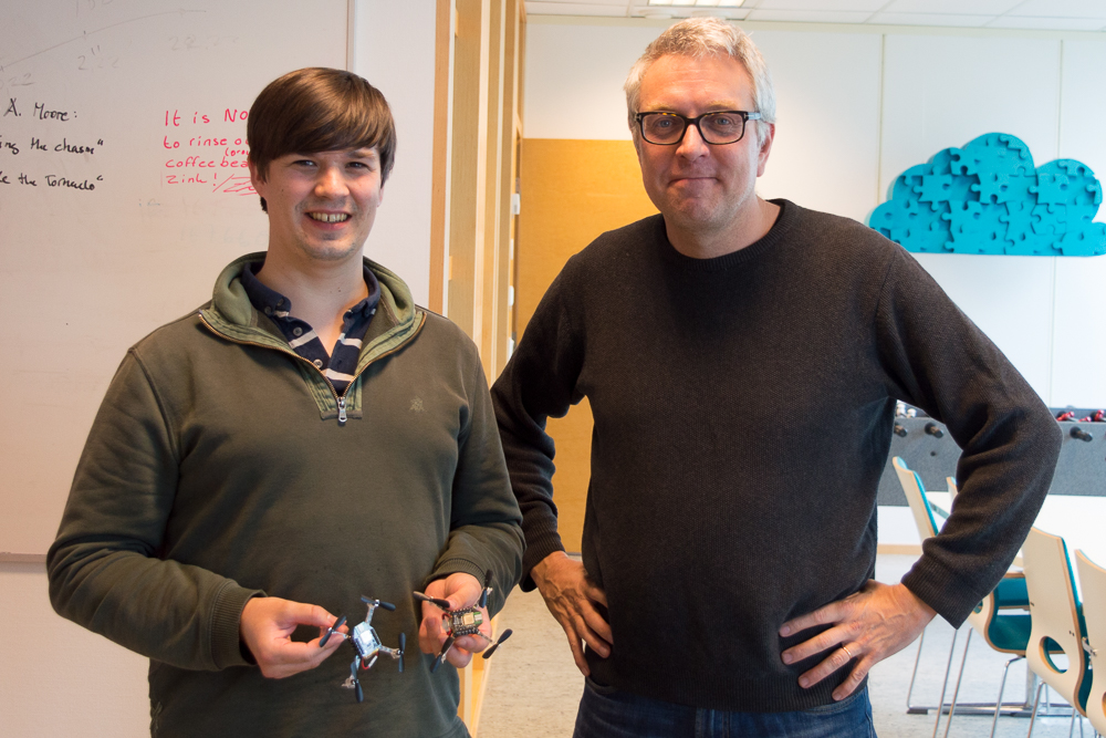
Kristoffer – co-worker

kristoffer

Kristoffer has a background as software developer in various areas such as synthesizers, audio/video compression, mobile phones, finance and web. Even though programming is his main trade, he has a keen interest in automation, test, agile methodologies and self organising companies. There will be interesting times ahead!

Theodor – intern

theodor

Theodor studies international trade in france and he will help us on the marketing side of our business.

Viswanth and Khalil – master theses

Viswanth and Khalil are studying wireless communication at LTH and are doing their master theses on dynamic mesh networks. They plan to finish their work in Q4.

MIT

While we are trying to fly over a kinect, this is what MIT is doing. Cool stuff!

Read the paper and look at the code in github.

On a side note, we have been featured on a website called eeweb. It contains lots of news about embedded electronics, nice to be featured.

So we are back at our office and the “great” Swedish weather. We don’t miss the California sunshine at all, we promise.

We have spent the last days documenting the setup we used to fly the Crazyflie autonomous using the Kinect2 for position control. It is still a work in progress but we think it worth sharing as we think many of you out there will be way better at improving it than we are. What we like so much with this setup is that it’s affordable compared to the professional systems such as VICON and PhaseSpace which makes it possible to play with at home, in the office or at school. It might be limiting in volume but until an affordable system such as the Valve’s lighthouse is available it is a pretty good alternative.

We have put all documentation on the wiki and hopefully it should be pretty straight forward to setup and get up and running.

crazyflie vision architecture


The Kinect uses its IR time of flight sensor to detect the altitude of the copter. The image processing is detecting the copter and then gets its position. The controller can the compare the current versus wanted position and then sends correction to bring the copter closer to the wanted position. These correction are sent to the copter until a new image is taken by the Kinect and a new correction is calculated. This closed loop process will keep the Crazyflie in the wanted position.

Here is a short video showing it in action.


We also thought it would be nice to show some more pictures from the Makar Faire Bay Area and our visit to USC!

We were at Maker faire bay area 2015 and that was an awesome experience! Thanks a lot to everyone that came to meet us.

Bitcraze booth

Our demos finally worked quite well. We had a Crazyflie flying autonomously for a total of about 24 hours during the faire and we could play music using a Crazyflie with a Buzzer expansion boards.

We are still in the US with limited Internet access but as soon as we return to the hyper-connected Sweden we will push codes and documentation Online so that you too can get autonomous flight with your Kinect 2.

So we did it again, forgot to post our Monday post on Monday. Are we getting sloppy or maybe it was the 16 hour travel to US that put us off track, well we need to shape up anyway! :) This Tuesday we have been visiting the USC robotics labs, more about that will come on a later post. Thanks Wolfgang for organising our visit and everybody for showing us around.

So now it is all about Maker Faire Bay Area for us. We have been putting in a lot of time to get the demos working and now we are getting really close. The autonomous control with Kinect 2 is starting to work but we must say, tuning the position PID controllers has turned out to be hard but we have some basic hovering working.

We have also been working on some LED-ring and buzzer control from the PC side. That is working really well and it is all setup using 0MQ to the cfclient. We are now able to play MIDI over the Crazyradio to the Crazyflie: MIDI -> 0MQ -> cfclient -> Crazyradio -> Crazyflie -> buzzer & LED-ring.

As soon as  we are back from Maker Faire we will make all the code available (because now it is in the quick and dirty stage)!

So once again, we would love to meet up so please come and visit ut as at our booth at the Maker Faire Bay Area!

Maker Faire Bay Area 2015

Yes, next week we are packing our bags and traveling the ~8500 Km from Malmö, Sweden to visit the Maker Faire Bay Area outside San Francisco and it is going to be great!

Malmö to Bay area We are planning some nice demos including autonomous flight with kinect2 and wireless computer controlled light effects using the LED-Ring so be sure to check us out! cf2 - kinect2 We are really looking forward to this event and we really hope you can pay us a visit if you are attending the Faire!

mf_bayarea_seeusthere