A while back we had a poll about when and how we should release new firmware and software. Since this we are aiming at at least doing a release every 7- 8 weeks of firmware/software that has been updated. So last week we branched and build release candidates of the firmware and the pc client. We will keep the RC until the end of the week or until we think it’s stable enough. During that time we will fix any serious bugs that come up. So if you are up for it download/flash it and give it a try. If you find any issues, don’t hesitate to let us know on the issue tracker (client / Crazyflie firmware).
Here are the files:
- Crazyfile PC client 2014.01-rc2 Windows Installer
- Crazyfile PC client 2014.01-rc2 source
- Crazyflie 2014.01-rc1 firmware
Some of the new features include:
- Client: Playstation 4 controller configuration
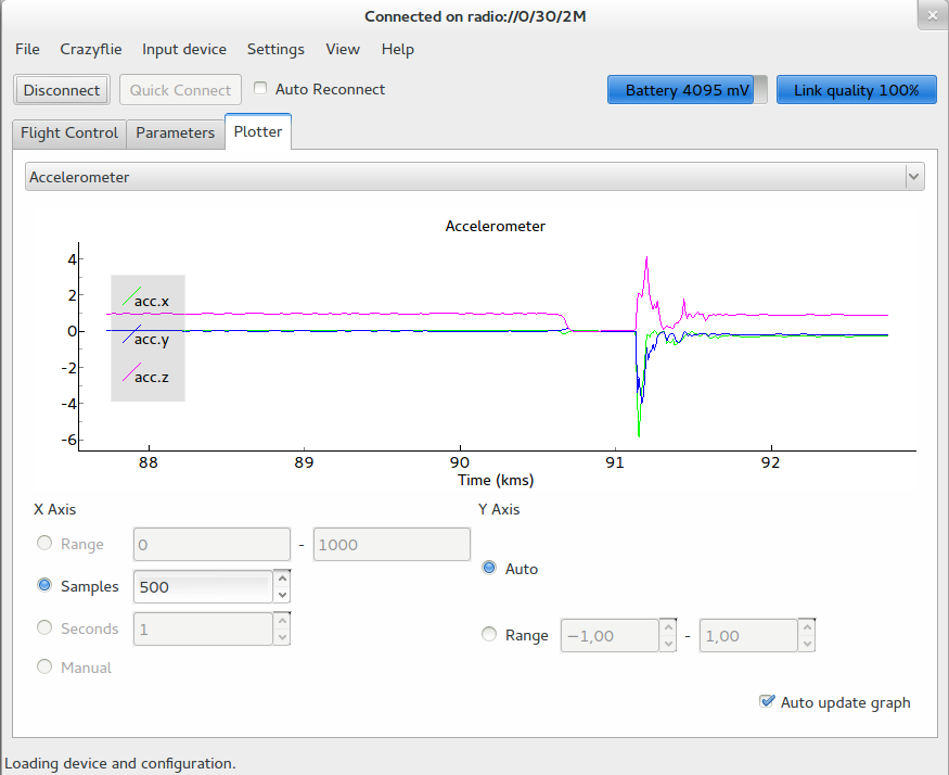
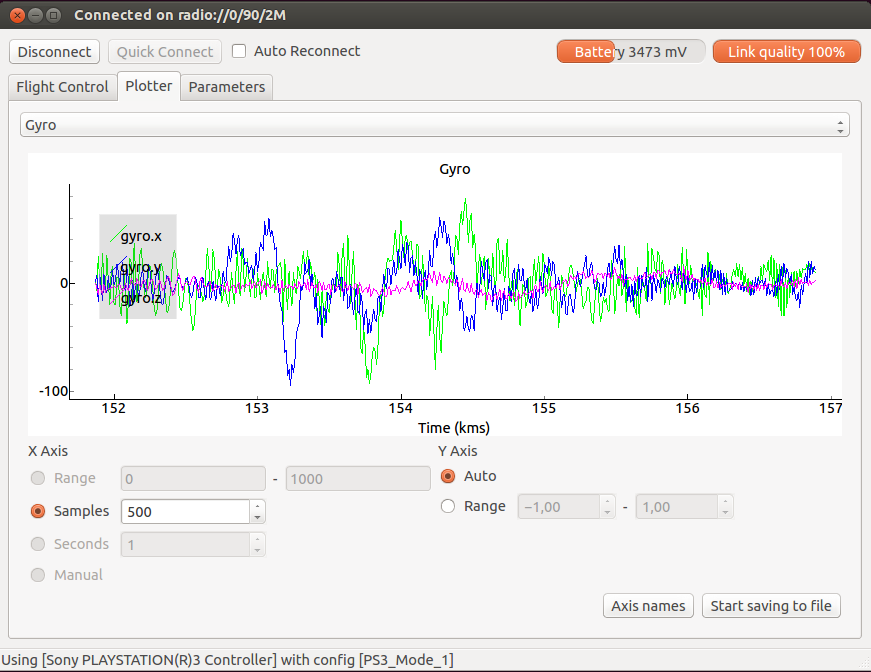
- Client: Improved plotting functionality (using PyQtGraph)
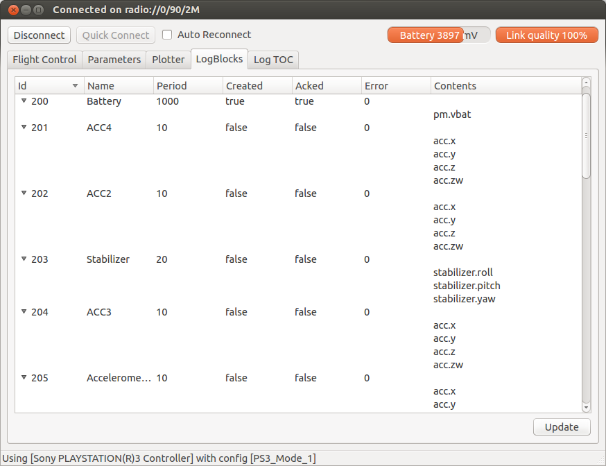
- Client: Improved logging functionality (UI and logging to file)
- Client: Added credits tab for Crazyflie PC client
- Client: Updated API for logging and crazyflie
- Client: Application icon added
- Client: Fixed bug that prevented using Crazyradio/pyusb if the software “gopro studio” was installed
- Client: Various bugfixes
- Firmware: A couple of new default log variables (acceleration, magnetometer)
- Firmware: Fix of the pitch/roll/yaw calculation: it is now correct all around roll.
We are also working on a Mac OSX release of the client using py2app. It’s not something that we have done before, but hopefully it will be ready by the next planned release (before 2014.03).
Last week we had a poll about moving to GitHub. For once there was a clear message from a poll, Move to GitHub! So after this release we will make the move. We will move things over gradually and in the move we will most likely make some structural changes as well, like splitting up the PC client and API into different repositories.
The last couple of weeks we have tried to become a bit more active on twitter (@bitcraze_se) and we will keep writing about smaller and bigger things that’s happening at Bitcraze. So if you are interested in keeping up to date this is a good source of info.