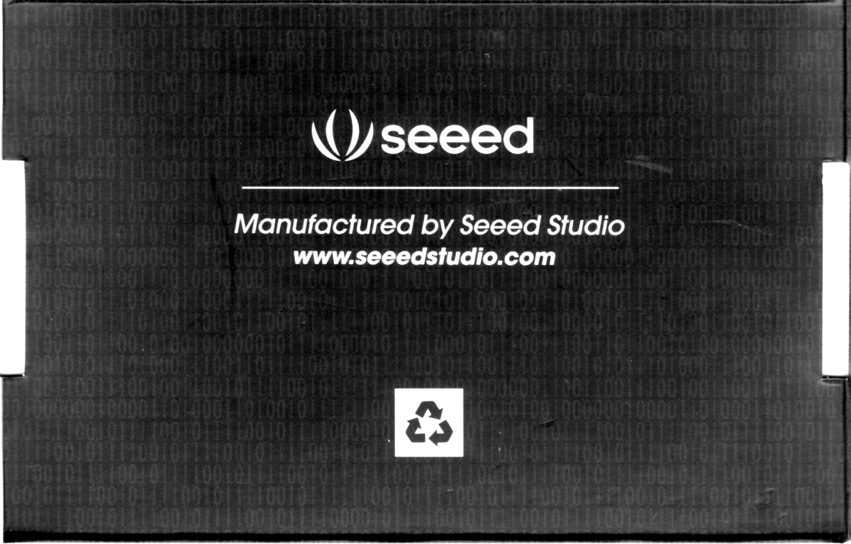
Blog

To begin with, we have just created a Bitcraze Announcement google-group that we will use as a very-low-volume mailing list to make big announcements like the release of Crazyflie. So if you are interested by buying Crazyflie just subscribe to the list and you will receive a mail as soon as it becomes available.


As for the project, we are now waiting for the next (and hopefully last) prototype run. In the mean time we are trying to fix everything from the todo-list. One item was to verify that the radio dongle can receive PPM signal from a RC remote, as it was designed for. This is what I  have been working on last week and the result hardware-wise is this kind of hacked programming/RC-training cable attached to our radio dongle:

The idea is to be able to control Crazyflie using a RC transmitter only (without a computer) so that the radio dongle would be powered and controlled by the RC transmitter. This kind of transmitter generates a PPM (Pulse Position Modulated) signal which is acquired from the training jack of our ‘Turnigy 9X’ transmitter. We do not plan to manufacture such cables right now as there are too much kind of RC transmitter around there  and we believe that you will be able to hook the Crazyradio dongle to your transmitter without problem :-).

As the cotper firmware can not fly easily without the PC yet (most of the settings are still sent from the PC software before flight) we decided, as a first step, to use the PC anyway but by using the radio dongle for the PPM acquisition:

A HID USB joystick mode has been added to the radio dongle so that it is now recognized as a joystick by the PC (in addition to the radio endpoints) and transmits the axis position of the RC transmitter to the PC. By mapping the axis the same way a Plastation3 gamepad is mapped we could fly Crazyflie with the RC remote and with an unmodified version of our PC software. This permitted to verify that the radio dongle can acquire PPM signals (with a little hardware change that has been sent just-in-time to our manufacturer for the next prototype) and so Crazyflie will also be able to fly without PC :-). In the case of our radio transmitter however we will have to connect the radio dongle to the TX module port instead of the training jack as the training jack does not provide power.

This is still work in progress and it is unlikely the ‘pc-free’ functionality will be finished before the copter release but at least now we know that the hardware can do it.

The last week we have been working hard on finishing the Crazyflie with the digital sensors, MPU-6050, HMC5883L and MS5611-01BA03. We are not so sure that the magnetometer,  HMC5883L, will work that well due to the strongly magnetized motors just a few centimeters from the sensor. That will be one of the upcoming tasks to find out.

Within 3-4 weeks we will receive what will hopefully be the final prototype version which later can be used for the first batch of Crazyflies. Until then we have plenty of work with software both on the PC side and the firmware. Now it is pretty late, the clock just passed 00:00 and writing at this hour is hard. We will post some video to compensate for this short post later this week :-)

Due to the IDG/ISZ-500 gyros EOL problem we are removing the  IDG/ISZ-500/BMA145 and going for the MPU-6050 instead. We where pretty certain the gyro part of the MPU-6050 would work but not so sure about the accelerometer.

To minimize the risk we wanted to try it out with our design before pushing the order button. We looked around for small IMUs with this chip and found that the FreeIMU uses the sensors that we are interested in testing. So we bought one and attached to the Crazyflie using the expansion connector. Here’s a image of what it looks like:

Since we now free up some space by replacing three sensor ICs with one we added a HMC5883L magnetometer and MS5611 pressure sensor which are the most common IMU sensors right now. If they will be mounted or not in the final version depends on cost and possible performance increase. If we don’t mount them there is always the possibility to do this yourself. Actually, as of this writing, we just made a virgin flight using the MPU-6050 data from the FreeIMU with good results.

We realized the other day that we have spent a lot of time discussing issues and developing stuff and not so much actual flying. We haven’t even left the rockie piloting stage… So when we met up on Sunday we spent a lot of time just flying around and having some fun :)

Here’s a first cut from some of the video we shot.

So as we were putting the finishing touches on what we hoped would be our last prototype before the final production version we noticed something rather serious on the InvenSense webpage. The IDG500/650 (and the ISZ-500/650) that we are using are EOL (and the LTB has passed). So this puts us in a rather tight spot where we have a couple of alternatives:

Stay with the IDG/ISZ 500/650 – We could stay with the sensors we have and try to source as many as possible but this would leave us in an awkward position if we get more demand than we can source gyros.

Analogue replacement – We could find an analogue replacement that would replace the X/Y and Z gyros we have today (that are analogue). The best candidate for this is currently the new ST gyro L3G462A but it is still under Evaluation and we don’t know if and when it will be available. It’s easy to put in our current design but we are unsure about the performance and immunity to vibrations.

Going digital – The most attractive option but the option that requires most work is switching from analogue to digital sensors. This is a step that we wanted to take eventually but taking it now delays everything but we do get a chance to get a bit more up to date by putting in a MPU-6050 and maybe a pressure sensor. But we are not sure how the sensors will respond to the vibrations and ripples on the supply voltage.

Our current plan is to drop the old analogue sensors from InvenSense and start on the digital design using the MPU-6050. We will keep the analogue ST gyro as a backup plan just in case we hit into any problems with the digital version.

Do you have any other ideas for sensors or comments about the performance of the MPU-6050 or L3G462A (if you managed to get a sample)?

When we built the latest prototypes we built two different versions. One with the ST accelerometer LIS344ALH and with the ISZ-IDG650 gyros. The other one with BOSH accelerometer BMA145 and with the ISZ-IDG500 gyros. It turned out that the LIS344ALH accelerometer is very vibration sensitive and doesn’t work that well for an application as this. If we would just have spent some time on the Internet we could have found this information in before hand… luckily we made the hardware design work with both and the BMA145 is working pretty well, however now we no longer have an alternative :-(.

The ISZ650 and IDG650 works pretty well even though they are less sensitive with their ±2000deg/s output. We can’t see any direct stability issues compared to the IXX500 versions with ±500deg/s output. Maybe we will stick with the IXX650, that way  we don’t limit the flip and loop speed to much. Not that the Crazyflie can do flips/rolls right now but we are very confident it will be able to in the future, judging from its agility.

We have also been working on getting the Crazyflie easier to control for beginners. With some slew rate limiting and thrust control we seem to be getting there. Now even Marcus can fly it without any problem. He used to hit the wall or ceiling all the time before :-).

Ever since we decided to make the Crazyflie available as a kit we have looked at different possibilities for manufacturing and selling it. Because we don’t have much time to spend (due to that we all have daytime jobs…) and rather spend or time doing development, we needed someone that could take care of manufacturing and selling it.

During development we have been cooperating with Seeedstudio for prototype manufacturing and component sourcing. We were really pleased with their work so we decided to continue the cooperation to also let them manufacture and sell the Crazyflie and the USBRadio dongle.

Currently the plan is to start out with a small series of 100 kits which will be a “DIY” version.  The motors/battery has to be soldered and the motor mounts attached. If you have some soldering skills it won’t be a problem to assemble.  The next step would then be to increase the volume and also offer a RTF kit where everything is assembled. The reason for not doing the RTF kit from the beginning is that it’s more time consuming since we have to specify testing requirements and packaging for the platform.

As for the price we still have no number but our hope are that it will be in the 100-200USD range. Since we are still working on the motor mounts and we are unsure of the assembly/testing cost for the platform we don’t know for sure how much the units will cost to produce. Once this is clear we will post more info of the pricing for the different kits (DIY/RTF and USBRadion dongle).


We had to cancel our weekly Monday meeting due to illnesses but we have at least made some small progress we can write about.

The radio dongle code has been updated to flash either of the two LED’s when sending data or in case of bad transmission.

On our latest prototypes we discovered that the radio transmission went pretty bad on some copters as soon as the motors where turned on. This was not a nice discovery at this time of our project and we had not really seen it before. This kind of problem could require a big re-design of the PCB! After some debugging it turned out to be the PWM switching of the motors causing ripple on the digital supply voltage. It wasn’t that much, about 60mV peak-to-peak but enough to throw the radio off balance. After some tries with different decoupling techniques to get rid of the ripple, which showed only minor improvement, we increased the motor PWM frequency from 17kHz to 280kHz. That made the ripple go away, now about 10mV peak-to-peak, and so did the radio transmission problems, yeay!

To communicate with the Crazyflie we are using a custom radio protocol with almost-baseband 2.4GHz radio chips: the nRF24 family from Nordic semiconductor. This kind of radio chip is easy to cable, easy to use and require a very minimal software stack. Wifi or bluetooth would have required a lot more electronic and software so we chose to not use them for the Crazyflie. We however made sure to keep the possibility to add other radio on an expansion board (ie. both UART and SPI are available on the expansion connector).

One things with using a custom radio is that we have to make a computer interface in order to be able to communicate with the copter. We called it the Crazyradio dongle:


This radio dongle is built around a nRF24LU1p chip which contains, among other things, the radio transceiver, a 8051 microcontroller and an USB device peripheral. We wrote the firmware running in the nRF24LU1 from scratch and it is compiled with the SDCC compiler. This firmware source code is going to be open like the rest of the copter code.

The radio is bidirectional which permits to send command and receive telemetry from the copter. The bandwidth is not great but has been enough to debug the regulation. On the computer side we are using python and pyUsb to interface the radio dongle.

We have added a 10 pins connector that can be used to program the dongle for development purposes (the dongle can also be updated via USB) or to power the electronic and provide signals input/output. We designed the dongle in such a way that it is going to be possible to power it with up to 15V and to input a PPM signal. This will permit to use this radio dongle with a RC remote control (ie. to control the copter without the need of a PC).

One of the ideas with the Crazyflie was to make a simple flying platform and what’s simpler than just attaching the motors directly to the PCB? On our first prototypes we used hot-glue to attach the motors which work out pretty well. The problem was that when you crashed the motors often came loose, and in some cases, so did the wires attached to the motors. Reparing this turned out to be pretty teadious and it makes flying it a lot less fun, since the iteration time for trying new things becomes longer. We did a few tests with different protections, like soldering a ring of piano-wire, but when we decided to make a kit out of the Crazyflie we realized that we needed something that was easier to manufacture.

Since we could not find any off-the-shelf motor mounts we decided to make our own. Our idea is to place the motor in the mount and the mount on the wing. We have tried a few different solutions but the current leading design is one where we feed the cable from the mount out under the wing and to the soldering point for the wire. We have also made a telescopic version so it is possible to adjust the arm length for adjustable flight dynamics or to attach bigger propellers. After some more testing we will decide which one we will go for.

The CAD work is done in an open-source CAD tool named FreeCAD. After struggling for a while with an unstable versions, the 0.12 branch finally became very stable. The images below is the second iteration of prototypes that we have done using Shapeways. It’s is a 3D printing house in the Netherlands that has a great service where you upload models, choose what material you want them printed in, and then two weeks later you receive them in the mail! The durability is pretty good as well. We have only managed to break one, and that’s after a lot of violent crashes and a more fragile design.


FreeCAD showing a model of the motor mount prototype


Prototype 1 (shown in CAD model above)

Prototype 2

Crazyflie with Prototype 1 motormounts