Category: Crazyflie

After a busy fall of testing and fine-tuning, we’re thrilled to announce that the Brushless is now available! Our team has put in a lot of effort to ensure it meets our high standards, and we can’t wait for you to experience it.

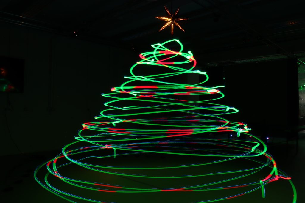
If you’re curious to see it in action, we’ve featured the Brushless in our recent Christmas video, where it showcases its capabilities by navigating through Christmas obstacles with precision.

For those interested in its application in research, our latest blog post demonstrates how the Brushless can be used in academic settings. It’s exciting to see the potential it holds for various fields!

If you need anything to keep your Brushless flying, all spare parts are already stocked in our store. Additionally, many of our bundles now offer Brushless versions, providing more options to suit your needs.

We’re eager to hear your thoughts and feedback as you explore the capabilities of our latest drone. Your insights are invaluable to us and help drive our continuous improvement.

We look forward to seeing what you’ll achieve with the Brushless!

Robotics and Simulation at FOSDEM 25

Arnaud will be at Fosdem the 1st and 2nd of February 2025 in Brussels, Belgium. He’s actually hosting with Kimberly the robotics and simulation dev-room! If you’re in Brussels, we’ll be happy to meet you.

Drones can perform a wide range of interesting tasks, from crop inspection to search-and-rescue. However, to make drones practically attractive they should be safe and cheap. Drones can be made safer by reducing their size and weight. This causes less damage in a collision with people or the environment. Additionally, being cheap means that the drones can take more risk – as it is less expensive to lose one – or that they can be deployed in larger numbers.

To function autonomously, such a drone should at least have some basic navigation capabilities. External position references such as GPS or UWB beacons can provide these, but such a reference is not always available. GPS is not accurate enough in indoor settings, and beacons require prior access to the area of operation and also add an additional cost.

Without these references, navigation becomes tricky. The typical solution is to have the drone construct a map of its local environment, which it can then use to determine its position and trajectories towards important places. But on tiny drones, the on-board computational resources are often too limited to construct such a map. How, then, can these tiny drones navigate? A subquestion of this – how to follow previously traversed routes – was the topic of my MSc thesis under supervision of Kimberly McGuire and Guido de Croon at TU Delft, and my PhD studies. The solution has recently been published in Science Robotics – “Visual route following for tiny autonomous robots” (TU Delft mirror here).

Route following

In an ideal world, route following can be performed entirely by odometry: the measurement and recording of one’s own movements. If a drone would measure the distance and direction it traveled, it could just perform the same movements in reverse and end up at its starting place. In reality, however, this does not entirely work. While current-day movement sensors such as the Flow deck are certainly accurate, they are not perfect. Every time a measurement is taken, this includes a small error. And in order to traverse longer distances, multiple measurements are summed, which causes the error to grow impractically large. It is this integration of errors that stops drones from using odometry over longer distances.

The trick to traveling longer distances, is to prevent this buildup of errors. To do so, we propose to let the drone perform ‘visual homing’ maneuvers. Visual homing is a control strategy that lets an agent return to a location where it has previously taken a picture, called a ‘snapshot’. In order to find its way back, the agent compares its current view of the environment to the snapshot that it took earlier. The trick here is that the difference between these two images smoothly grows with distance. Conversely, if the agent can find the direction in which this difference decreases, it can follow this direction to converge back to the snapshot’s original location.

The difference between images smoothly increases with their distance.

So, to perform long-distance route following, we now command the drone to take snapshots along the way, in addition to odometry measurements. Then, when retracing the route, the drone will routinely perform visual homing maneuvers to align itself with these snapshots. Because the error after a homing maneuver is bounded, there is now no longer a growing deviation from the intended path! This means that long-range route following is now possible without excessive drift.

Implementation

The above mentioned article describes the strategy in more detail. Rather than repeat what is already written, I would like to give a bit more detail on how the strategy was implemented, as this is probably more relevant for other Crazyflie users.

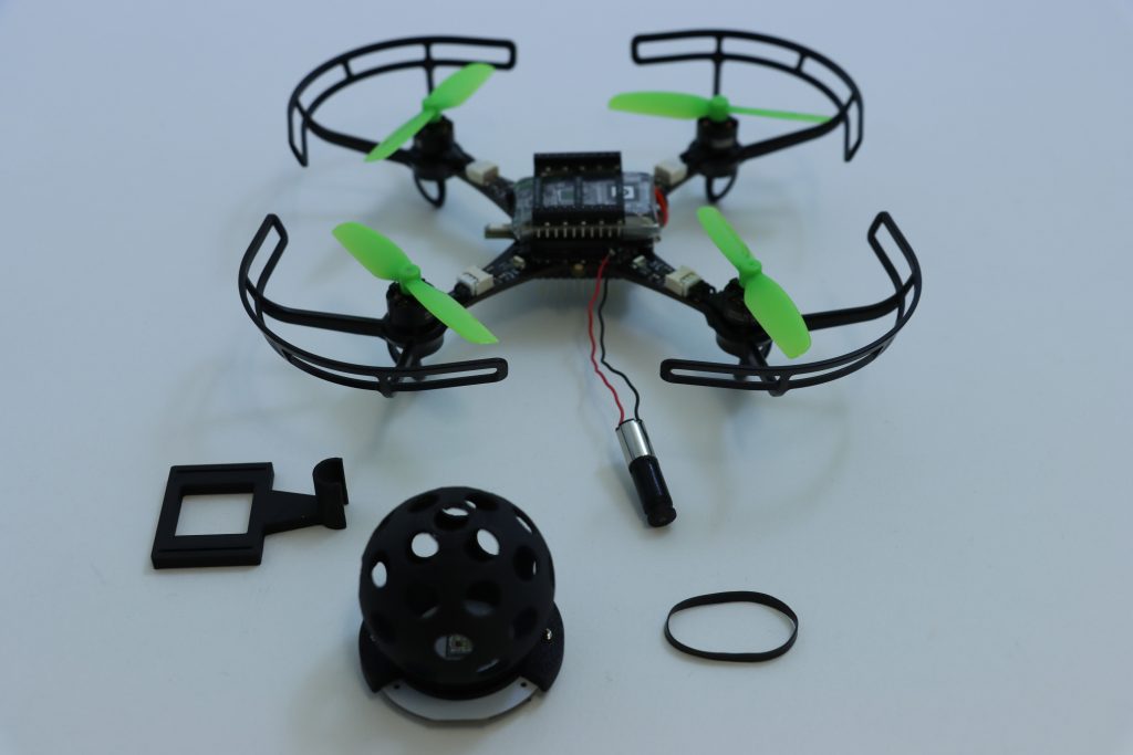
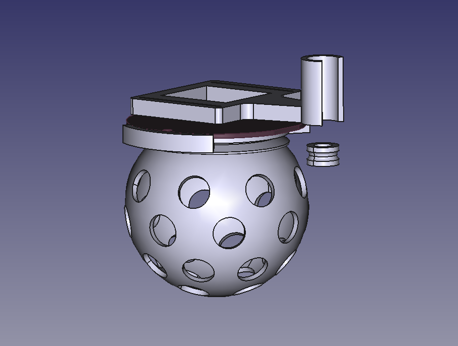
The main difference between our drone and an out-of-the-box one, is that our drone needs to carry a camera for navigation. Not just any camera, but the method under investigation requires a panoramic camera so that the drone can see in all directions. For this, we bought a Kogeto Dot 360. This is a cheap aftermarket lens for an older iPhone that provides exactly the field-of-view that we need. After a bit of dremeling and taping, it is also suitable for drones.

ARDrone 2 with panoramic camera lens.

The very first visual homing experiments were performed on an ARDrone 2. The drone already had a bottom camera, to which we fitted the lens. Using this setup, the drone could successfully navigate back to the snapshot’s location. However, the ARDrone 2 hardly qualifies as small as it is approximately 50cm wide, weighs 400 grams and carries a Linux computer.

To prove that the navigation method would indeed work on tiny drones, the setup was downsized to a Crazyflie 2.0. While this drone could take off with the camera assembly, it would become unstable very soon as the battery level decreased. The camera was just a bit too heavy. Another attempt was made on an Eachine Trashcan, heavily modified to support both the camera, a flowdeck and custom autopilot firmware. While this drone had more than enough lift, the overall reliability of the platform never became good enough to perform full flight experiments.

After discussing the above issues, I was very kindly offered a prototype of the Crazyflie Brushless to see if it would help with my experiments. And it did! The Crazyflie brushless has more lift than the regular platform and could maintain a stable attitude and height while carrying the camera assembly, all this, with a reasonable flight time. Software-wise it works pretty much the same as the regular Crazyflie, so it was a pleasure to work with. This drone became the one we used for our final experiments, and was even featured on the cover of the Science Robotics issue.

With the hardware finished, the next step was to implement the software. Unlike the ARDrone 2 which had a full Linux system with reasonable memory and computing power, the Crazyflie only has an STM32 microcontroller that’s also tasked with the flying of the drone (plus an nRF SoC, but that is out of scope here). The camera board developed for this drone features an additional STM32. This microcontroller performed most of the image processing and visual homing tasks at a framerate of a few Hertz. However, the resulting guidance also has to be followed, and this part is more relevant for other Crazyflie users.

To provide custom behavior on the Crazyflie, I used the app layer of the autopilot. The app layer allows users to create custom code for the autopilot, while keeping it mostly decoupled from the underlying firmware. The out-of-tree setup makes it easier to use a version control system for only the custom code, and also means that it is not as tied to a specific firmware version as an in-tree process.

The custom app performs a small number of crucial tasks. Firstly, it is responsible for communication with the camera. Communication with the camera was performed over UART, as this was already implemented in the camera software and this bus was not used for other purposes on the Crazyflie. Over this bus, the autopilot could receive visual guidance for the camera and send basic commands, such as the starting and stopping of image captures. Pprzlink was used as the UART protocol, which was a leftover from the earlier ARDrone 2 and Trashcan prototypes.

The second major task of the app is to make the drone follow the visual guidance. This consisted of two parts. Firstly, the drone should be able to follow visual homing vectors. This was achieved using the Commander Framework, part of the Stabilizer Module. Once the custom app was started, it would enter an infinite loop which ran at a rate of 10 Hertz. After takeoff, the app repeatedly calls commanderSetSetpoint to set absolute position targets, which are found by adding the latest homing vector to the current position estimate. The regular autopilot then takes care of the low-level control that steers the drone to these coordinates.

The core idea of our navigation strategy is that the drone can correct its position estimate after arriving at a snapshot. So secondly, the drone should be able to overwrite its position estimate with the one provided by the route-following algorithm. To simplify the integration with the existing state estimator, this update was implemented as an additional position sensor – similar to an external positioning system. Once the drone had converged to a snapshot, it would enqueue the snapshot’s remembered coordinates as a position measurement with a very small standard deviation, thereby essentially overwriting the position estimate but without needing to modify the estimator. The same trick was also used to correct heading drift.

The final task of the app was to make the drone controllable from a ground station. After some initial experiments, it was determined that fully autonomous flight during the experiments would be the easiest to implement and use. To this end, the drone needed to be able to follow more complex procedures and to communicate with a ground station.

Because the cfclient provides most of the necessary functions, it was used as the basis for the ground station. However, the experiments required extra controls that were of course not part of a generic client. While it was possible to modify the cfclient, an easier solution was offered by the integrated ZMQ server. This server allows external programs to communicate with the stock cfclient over a tcp connection. Among the possibilities, this allows external programs to send control values and parameters to the drone. Since the drone would be flying autonomously and therefore low-frequencies would suffice, the choice was made to let the ground station set parameters provided by the custom app. To simplify usability, a simple GUI was made in python using the CFZmq library and Tkinter. The GUI would request foreground priority such that it would be shown on top of the regular client, making it easy to use both at the same time.

Cfclient with experimental overlay (bottom right).

To perform more complex experiments, each experiment was implemented as a state machine in the custom app. Using the (High-level) Commander Framework and the navigation routines described above, the drone was able to perform entire experiments from take-off to landing.

While the code is very far from production quality, it is open source and can be viewed here to see how everything was implemented: https://github.com/tomvand/2020-visualhoming-crazyflie . The PCB used to fit Crazyflie decks to the Eachine Trashcan can be found here: https://github.com/tomvand/cf-deck-carrier .

Outcome

Using the hardware and software described above, we were able to perform the route-following experiments. The drone was commanded to fly a preprogrammed trajectory using the Flow deck, while recording odometry and snapshot images. Then, the drone was commanded to follow the same route in reverse, by traveling short sections using dead reckoning and then using visual homing to correct the incurred drift.

As shown in the article, the error with respect to the recorded route remained bounded. Therefore, we can now travel long routes without having to worry about drift, even under strict hardware limitations. This is a great improvement to the autonomy of tiny robots.

I hope that this post has given a bit more insight into the implementation behind this study, a part that is not often highlighted but very interesting for everyone working in this field.

As 2024 comes to an end, it’s the perfect time to reflect on what we’ve accomplished over the past year. A major highlight has been our work on the Crazyflie 2.1 Brushless. We’re thrilled that it will be available early in the new year! While much of our efforts focused on refining and preparing the platform as a whole, we also introduced some standout features like support for contact charging on a charging pad, perfecting the specially optimized motors, and propeller guards to enhance safety for both users and the drone.

Finalizing the integration of the Crazyflie 2.1 Brushless into our software ecosystem and expanding its documentation were key steps in preparing for its launch. These efforts ensure compatibility, improve the user experience, and make the platform more accessible to the community. We’re looking forward to a smooth launch and to seeing how the community will utilize the new platform!

This year, we introduced updates to the Crazyflie 2.1 kit, making the 47-17 propellers the new default and including an improved battery. These upgrades enhance flight performance and endurance, culminating in the release of the Crazyflie 2.1+—an optimized iteration of our established platform.

The Crazyflie 2.1 Brushless featured on the cover of Science Robotics vol. 9, no. 92

Community

In 2024, Bitcraze had an action-packed year, engaging with the robotics community through numerous conferences, workshops, and live events.

In May, we attended ICRA 2024 in Yokohama. We collected several research posters that now proudly feature at the office. Kimberly presented at the Robotics Developer Day, where she won Best Speaker Award for her impressive live hardware demos with ROS2. We co-organized the ‘Aerial Swarm Tools and Applications’ workshop at RSS 2024 in Delft. Arnaud and Kimberly shared insights on demo-driven development on an episode of OpenCV Live!. Additionally, we had a booth at ROSCon ’24 in Odense, connecting with the vibrant ROS community and showcasing our latest developments.

And don’t forget the developer meetings, where we shared some more behind the scenes information and collected invaluable feedback from the community.

We also released a new edition of our research compilation video, showcasing some of the coolest projects from 2023 and 2024 that highlight the versatility and impact of the Crazyflie platform in research.

Team

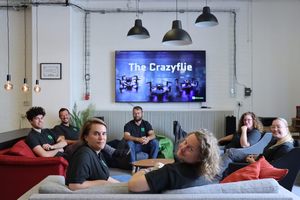
In the past year, Bitcraze saw significant changes within the team. in February, Rik rejoined the team. Tove started at Bitcraze in April. Mandy, with whom we’ve already worked extensively over the years, joined as our production representative in Shenzen. At the end of the year, we said goodbye to Kimberly, whose contributions will be deeply missed. Additionally, we had Björn with us for a few months, working on his master’s thesis on fault detection, and Joe continued his industrial postdoc at Bitcraze that began in December 2023. Looking ahead, Bitcraze is hiring for two new roles: a Technical Sales Lead and a Technical Success Engineer, to support our ongoing projects and customer collaborations.


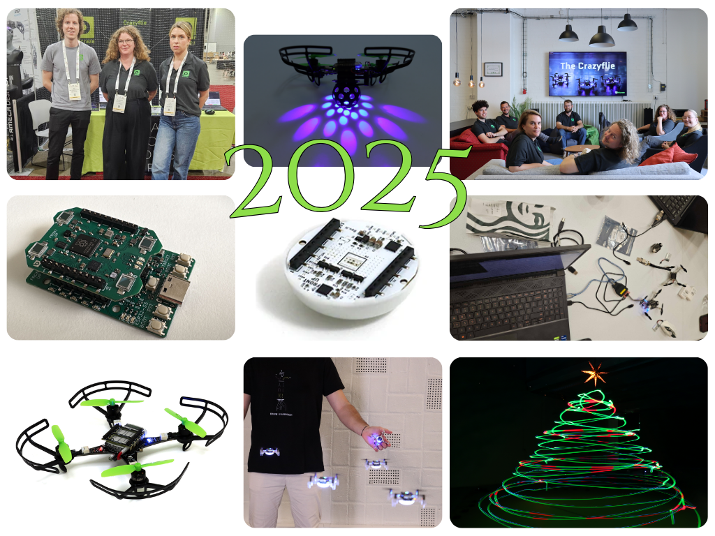
As we close the chapter on 2024, we’re proud of the progress we’ve made, the connections we’ve strengthened, and the milestones we’ve reached. With exciting launches, new faces on the team, and continued collaboration with our community, we’re ready to soar to even greater heights in 2025. Thank you for being part of our journey!

The last couple of months we have been working really hard on finalizing the Crazyflie 2.1 Brushless and we’re happy to say that we’re finally nearing the release date! The first units are scheduled to be finished during December with shipping in January. Make sure so sign up for the Crazyflie 2.1 brushless product notifications to not miss out once it’s available!

We’re also working hard to offer everything that complements the Brushless. You’ll have access to spare parts and the option to choose your platform for some bundles. Hopefully, the charger will also been available soon, to allow you to charge the Brushless effortlessly!

Today, we’re excited to share research from Vrije Universiteit Amsterdam, ‘From Shadows to Light,’ which presents an innovative swarm robotics approach where nano-drones autonomously track dynamic sources indoors.

Motivation

In dynamic and unpredictable indoor environments, locating moving sources—such as heat, gas, or light—presents unique challenges. GPS-denied settings, in particular, demand innovative and efficient onboard solutions for both control and sensing. Our research demonstrates how small drones, like Crazyflies, can be organized into a coordinated swarm to autonomously locate and follow these sources indoors, relying solely on onboard sensing and communication capabilities. Without sharing individual measurements, each drone adapts its behavior in response to its own sensor readings, allowing the swarm to collectively converge on the center of a light source through modified interactions with nearby agents.

Tugay Alperen (right) and Victor Retamal (left) during ICRA 2024 poster session

Method

Our approach enables each Crazyflie to function autonomously, using onboard sensing combined with continuous inter-agent communication at a frequency of 20 Hz. This methodology is structured around three core components:

Proximal Control and Collective Motion

Each drone broadcasts its position to nearby agents, enabling the calculation of relative positions to maintain safe distances. This proximal control ensures cohesive group movement by computing virtual force vectors for velocity commands, which are sent to onboard controllers operating at 20 Hz.

Source Seeking Through Adaptive Social Proximity

Drones use custom light sensors to detect local light intensity. Instead of directly adjusting positions based on this measurement, each drone modifies its social proximity to neighbors according to the sensed intensity without broadcasting this information. This adaptation allows the swarm to collectively follow the light gradient toward the source in a decentralized manner.

Obstacle Avoidance

Equipped with time-of-flight sensors, each drone independently detects obstacles and adjusts its trajectory to maintain safety. This ensures the swarm remains intact while navigating toward the source.

By combining continuous relative positioning, virtual force-based control, individual sensing, and adaptive social behavior, our methodology provides a robust framework for efficient source seeking in GPS-denied indoor environments.

Experimental Setup

Crazyflie equipped with Flow Deck v2, UWB Deck, Multi-Ranger Deck, and a custom-made deck that produces an analog voltage reading from an LDR for light intensity measurements.

The system architecture allowing us to achieve autonomous flocking and source localization with a swarm of Crazyflie

Our experiments take place in a 7×4.75-meter indoor arena with remotely controlled overhead light bulbs. These bulbs, activated individually or in pairs, create a moving light gradient. We tested our flocking swarm by initially positioning them at the edge of an illuminated area. As the light source shifted, we assessed the swarm’s performance by comparing their trajectories with the known centers of the illuminated areas without waiting for full convergence at each step. We also mapped our environment’s light intensity by moving a single Crazyflie randomly around the flight arena and recording the measurements to later merge on a single map to generate this light intensity heatmap.

The brightness values around the test environments, measured for each light source when only it was active.

Results

The flock flies as an ordered swarm, successfully localizing around the source with the swarm’s centroid positioned at the source center. (The centroid appears as a point without an arrow in the video.)

Even with an obstacle present within or between the illuminated regions, the flock successfully localizes around the center, avoiding the obstacle and maintaining order and cohesion within the swarm. The Multi-Ranger deck provides distance measurements for obstacle detection.

Future Directions

As the next step, we plan to apply our highly generalizable algorithm to various source types, including gas sources, radio signals, and similar sources that provide only scalar strength measurements rather than directional cues. Additionally, we have demonstrated that our flocking and source localization algorithms work effectively in 3D. We aim to showcase a fully functional application with a 3D-localized source and a flocking swarm operating in 3D space. Finally, we are working toward achieving fully onboard relative localization, which would eliminate the need for any indoor positioning system. This advancement would allow our swarm to operate autonomously in any environment, replicating the same behavior wherever it is deployed.

Links

The authors were with the Vrije Universiteit Amsterdam.

Please feel free to contact us with any questions or ideas: t.a.karaguzel@vu.nl

Please cite this as:

@ARTICLE{10314746,
  author={Karagüzel, Tugay Alperen and Retamal, Victor and Cambier, Nicolas and Ferrante, Eliseo},
  journal={IEEE Robotics and Automation Letters}, 
  title={From Shadows to Light: A Swarm Robotics Approach With Onboard Control for Seeking Dynamic Sources in Constrained Environments}, 
  year={2024},
  volume={9},
  number={1},
  pages={127-134},
  keywords={Robot sensing systems;Autonomous aerial vehicles;Position measurement;Vehicle dynamics;Sensors;Location awareness;Drones;Swarm robotics;aerial systems: perception and autonomy;multi-robot systems},
  doi={10.1109/LRA.2023.3331897}}

We are excited to announce that we are working on several new link performance metrics for the Crazyflie that will simplify the troubleshooting of communication issues. Until now, users have had access to very limited information about communication links, relying primarily on a “link quality” statistic based on packet retries (when we have to re-send data) and an RSSI channel scan. Our nightly tests have been limited to basic bandwidth and latency testing. With this update, we aim to expose richer data that not only enables users to make more informed decisions regarding communication links but also enhances the effectiveness of our nightly testing process. In this blog post, we will explore the new metrics, the rationale behind their introduction, and how they will improve your interaction with the Crazyflie. Additionally, we will be holding a developer meeting on Wednesday November 13th to discuss these updates in more detail, and we encourage you to join us!

“Link Quality”—All or Nothing

Until now, users of the Crazyflie have had access to a single link quality metric. Implemented in the Python library, this metric is based on packet retries—instances when data packets need to be re-sent due to communication issues. This metric indicates that for every retry, the link quality drops by 10%, with a maximum of 3 retries allowed. As a result, the link quality score usually ranges from 70% to 100%, with a drop to 0% when communication is completely lost. However, as packet loss occurs, users often experience a steep decline, commonly seeing 100% when packets are successfully acknowledged or dropping to 0% when communication is completely lost.

Client representation of link quality; no link, yes link

The current link quality metric has served as a basic indicator but provides limited insight, often making it difficult to gauge communication reliability accurately. Recognizing these limitations, we’re introducing several new link performance metrics to the Crazyflie Python library, designed to provide a far more detailed and actionable view of communication performance.

What’s Coming in the Upcoming Update

The first metric we are adding is latency. We measure the full link latency, capturing the round-trip time through the library, to the Crazyflie, and back. This latency measurement is link-independent, meaning it applies to both radio and USB connections. The latency metric exposed to users will reflect the 95th percentile—a commonly used measure for capturing typical latency under normal conditions.

Next are several metrics that (currently) only support the radio link. For these, we distinguish between uplink (from the radio to the Crazyflie) and downlink (from the Crazyflie to the radio).

The first is packet rate, which simply measures the number of packets sent and received per second.

More interestingly, we are introducing a link congestion metric. Whenever there is no data to send, both the radio and the Crazyflie send “null” packets. By calculating the ratio of null packets to the total packets sent or received, we can estimate congestion. This is particularly useful for users who rely heavily on logging parameters or, for example, stream mocap positioning data to the Crazyflie.

The Received Signal Strength Indicator (RSSI) measures the quality of signal reception. Unlike our current “link quality” metric, we hope that a poor RSSI will serve as an early warning signal for potential communication loss. While RSSI tracking has been possible before with the channel scan example, this update will monitor RSSI in the library by default, and expose it to the user. The nRF firmware will also be updated to report RSSI by default. Currently, we only receive uplink RSSI, that is, RSSI measured on the Crazyflie side.

Work in progress client representation of new link performance metrics

We’ve already found these new metrics invaluable at Bitcraze. While we have, of course, measured various parameters throughout development, it was easy to lose track of the precise status of the communication stack. In the past, we relied more on general impressions of performance, but with these new metrics, we’ve gained a clearer picture. They’ve already shed light on areas like swarm latency, helping us fine-tune and understand performance far better than before.

You can follow progress on GitHub, and we invite you to try out these metrics for yourself. If there’s anything you feel is missing, or if you have feedback on what would make these tools even more helpful, we’d love to hear from you. Hit us up over on GitHub or join the developer meeting on Wednesday the 13th of November (see the join information on discussions).

We are happy to announce that release 2024.10 is now available! Special thanks to our community contributors for their valuable input and code contributions in this release!

Release overview

crazyflie-firmware release 2024.10 GitHub

crazyflie2-nrf-firmware release 2024.10 GitHub

crazyflie2-nrf-bootloader release 2024.10 GitHub

cfclient (crazyflie-clients-python) release 2024.10 GitHub, PyPI

cflib (crazyflie-lib-python) release 0.1.27 on GitHub, PyPI

User upgrade notice

While older versions may still function, users are encouraged to upgrade:

  • Minimum supported Python version changed to 3.10
  • Supported Ubuntu versions changed to 22.04 and 24.04

Major changes

  • Enhanced out-of-tree (OOT) kbuild configuration, allowing users to perform full Kconfig configuration for app layer applications.
  • Introduced recovery functionality, allowing users or scripts to safely re-enable the system after a crash without reboot.
  • Added a timeout for auto-disarming, allowing the system to remain armed during brief landings in manual arming mode.
  • Introduced a workaround for PID derivative kick, improving the performance of the PID controller during large setpoint changes (#1337, #1403).
  • Spiral and constant velocity high-level commander segments (#1410).
  • Changed BLE name format to include part of the NRF MAC address, allowing users to easily differentiate between Crazyflies.

For detailed release notes, check out the individual releases on GitHub. Links can be found in the release overview above.

Ever since we started going to fairs to show off the Crazyflies, we’ve been trying to push the boundaries for the demos. Often we’ve used the fairs as an opportunity to either develop new functionality or try out new ideas. Something we’ve always been interested in, especially for fairs, is autonomous flights. It’s hard to talk to people about the Crazyflie while trying to fly it at the same time. Back in 2015 we were using the Kinect for piloting the Crazyflie at the Bay Area Maker Faire. Although awesome, we had a slight issue: we needed to switch batteries on the Crazyflie each flight. We had a Qi deck for wireless charging but no positioning system good enough to use it for landing on a charger.

Latest iteration of the Crazyflie Brushless charger

In 2018 we were really excited when we got to borrow a motion capture system from Qualisys and could finally land on a Qi charger (3D printed base and an IKEA Qi charger). First time we showed this off was at IROS in Madrid 2018. The following year we improved the demo to have more Crazyflies and switched to the Lighthouse positioning system at ICRA 2019. Since then each year we have been improving the demo until we’ve reached the current state we showed off at IROS 2022 in Kyoto.

So since 2018 we’ve been using the Qi wireless charging for our demos. Many customers have purchased the Qi charging deck, but building a matching charging platform has always required some effort. So, a while back we started looking at something that could replace the Qi deck, with a lighter solution which would also allow users to have other decks with electronics facing downwards. The first prototypes were made with the Crazyflie 2.1 back in 2021 using decks, but they were a bit clumsy. For one thing you needed the charging solution to be integrated on each deck.

When work started on the Crazyflie Brushless we realized we had the possibility to integrate the charge points directly on the main PCB which meant we could still use any decks we wanted and get the charging. So the prototypes from 2021 were reshaped into something we could use with the Crazyflie Brushless. Although the prototypes worked well, they were pretty big and packed with features which weren’t needed for charging (like LED lights and WiFi). Another iteration and the chargers have now gone down in size and complexity. The latest iteration only has charging and is powered via our 12V power block or 5V USB-C.

Over the years lots of customers have asked us for buying the Qi charger, since many users do not have the capabilities to build their own. Unfortunately we’ve never gotten around to it, but with the release of the Crazyflie Brushless we would like to change this. The release is only a few months away so we’re short on time for remaking the design so it’s usable for plastic molding. Instead the plan is to make a limited amount of prototypes available to our users, based on the same 3D printed design and electronics we’re currently using in our flight lab, at the time of release. This will enable our users to easily try out the design and create their own autonomous demos which will keep flying for a long time.

As you might expect, we use the Crazyflie python client a lot at Bitcraze. The client has a lot of features, ranging from setting up LPS/Lighthouse systems to turning on/off the headlight LEDs on the LED-ring deck. But some of the features we use the most is probably the console view as well as the logging/parameter subsystems. A lot of the time we modify firmware, flash it and want to tweak (via parameters) or to check if the changes are working as expected (via the console or logging). Then switching from the terminal, where we build/flash, to the Qt UI in the Crazyflie python client can be a hassle if you just want to do something quick. It would be great to be able to log/set variables directly from the terminal, well now you can!

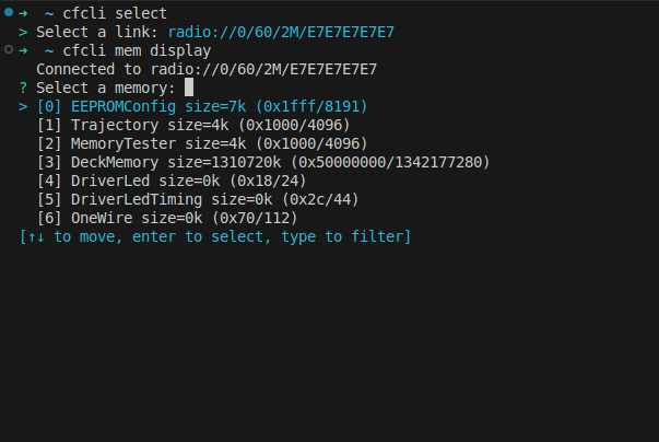
Meet the Crazyflie command-line client, a fun Friday project I worked on a while back. The CLI is written in Rust and was made possible thanks to a previous fun Friday project by Arnaud on the Rust Crazyflie link/lib, which has now moved to the official Bitcraze repositories. The CLI project is still very limited, but has some basic functionality:

  • Scan for Crazyflies and pre-select one to interact with
  • List loggable variables, create log configurations and print their value
  • List parameters and get/set them
  • Show the Crazyflie console

Last week the first version, v0.1.0, was released on crates.io. So if you have Rust set up on your computer and want to test it out then all you need to do is to type “cargo install cfcli“. The CLI still only has some basic functionality, but hopefully it can be expanded in the future with more useful things! Feel free to leave any issues or comments you might have on the Github page.

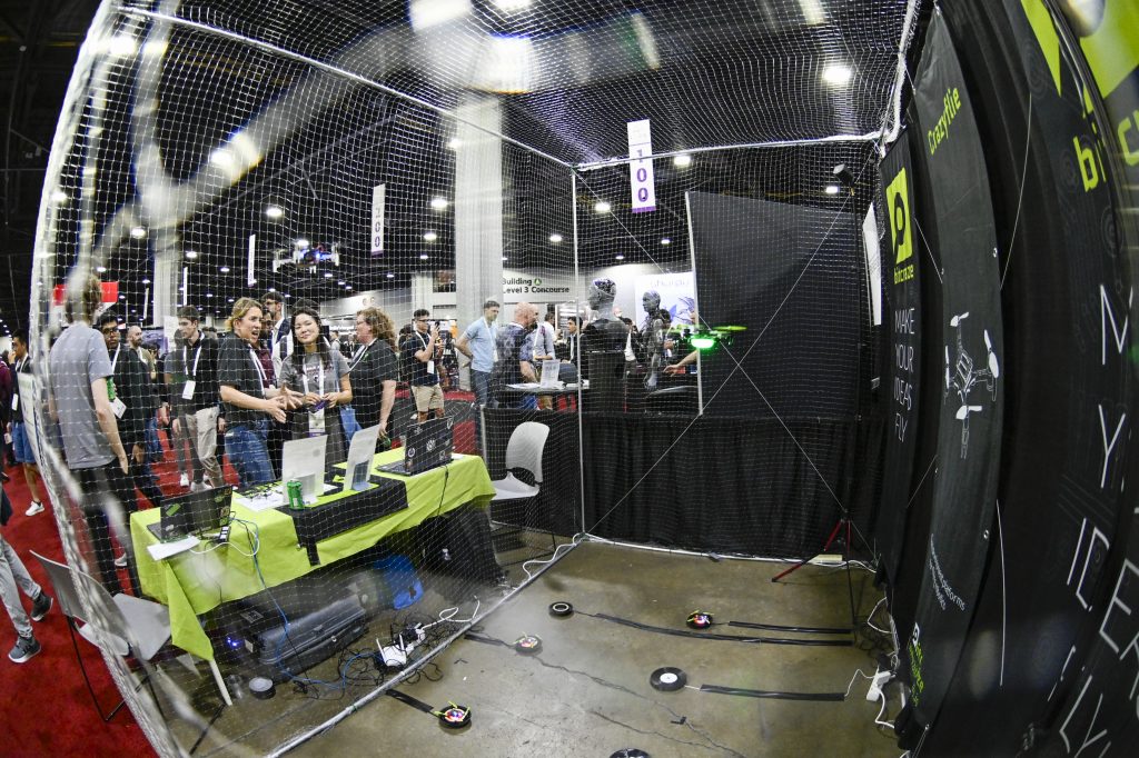
ROSCon is a developer’s conference that focuses entirely on the Robot Operating System (ROS), bringing together developers from around the globe to learn, discuss, and network. It serves as a space for ROS developers to explore the latest advancements, share their experiences, and collaborate on cutting-edge robotics projects. We attended ROSCon 2022 in Japan, and it was a fantastic experience. So when the opportunity came to participate again this year, we couldn’t pass it up! Not only is this a conference that’s been close to our hearts, this year it’s also close to the office: it’s merely a 3hours train ride away.

The 2024 edition is full of promises already, and we’re excited to be a part of it in several ways. We talked about how we helped out the diversity committee already, contributing to efforts that promote a more inclusive and diverse community within the robotics field. Moreover, we will have a booth there. We’ll be located at in Room 2, at booth 21. If you have trouble finding us, just listen closely to the sound of drones buzzing! ! We’ll be showcasing a live demo that’s still under construction. If you’re curious and want to know more about it, just keep an eye on our weekly blogposts to get an update once we finalize our plans.

In addition to being an exhibitor, we also have the honour of presenting a talk. Arnaud will be speaking on October 23 at 14:40 in Large Hall 4. His talk, titled “The Lighthouse Project: From Virtual Reality to Onboard Positioning for Robotics”, will dive into the Lighthouse system, as the title implies. He’ll explain how this technology, originally developed for virtual reality, is being adapted for onboard positioning in various types of robots.

We’re really looking forward to connecting with fellow developers, learning from the presentations, and sharing our own work with the community. If you’re attending ROSCon 2024, be sure to stop by Booth 21 and catch Arnaud’s talk—we can’t wait to see you there!