It has been a while since we have done an update on the AI-deck! However, as announced in the New Year post, we do have some important changes coming up for the next batch of production. These changes include updated version of the GAP8 chip and switching to a gray-scale camera. We will call this version the AI-deck 1.1, but its firmware should be compatible with the previous version. Currently we don’t have a clear time-line of when we will receive the next batch but it will be soon.
Newer version of GAP8
Together with our collaborators at Greenwaves technologies, we decided to update the GAP8 chip to the latest version available. Since this required a microchip change on the product and to prevent any confusion, we decided to call this version the AIdeck 1.1.
The new version of the GAP8 chip includes several improvements, which resolves 1. conflict problem between uart and hyperbus and 2. Cluster DMA when doing the data transfer between L2 and L1 Memory. The last issue is considered a corner case will only occur if the AI-deck 1.0 is pushed to its limit with a large deep neural network. Although we expect that both issues will not affect the current users if you are experiencing any related problems with the previous version (AI-deck 1.0), please send us an email to contact@bitcraze.io.
Gray-scale Camera
In July we have given an update where we discussed the color camera and how to process it on the GAP8 chip. Even though at the first we were pretty optimistic on the possibilities with the camera, after discussing with the community, ETH zurich and Greenwaves T., we have decided to switch back to a gray-scale camera.
This is because most examples in the gap_sdk repo mostly assume a gray-scale camera. And even though the color camera would be good for image processing with anything of color, it is less ideal for neural networks on edge machine learning devices.
For those who committed themselves to the color camera module, do not worry! We are planning to still offer the color camera module as a separate product in our store! Also we will have a limited amount of grayscale cameras available for those who are unhappy with their AI-decks 1.0’s color camera.
Firmware, Docs and Examples
Since the AI-deck is still in early release, have all the code and documentation in this github repository. This contains all the start-up guides and keeps track of all the bugs and fixes. Some months ago, we managed to update all of this to the latest GAP SDK (3.8.1), which fixed the streamer issues we are having.
However, the quickest way on how to improve this Early Release product is to get feedback by its users. So if you are having any problems at all, do not hesitate to ask a question on to forum or to open up a issue in the repository!
This autumn when we had our quarterly planing meeting, it was obvious that there would not be any conferences this year like other years. This meant we would not meet you, our users and hear about your interesting projects, but also that we would not be forced to create a demo. Sometimes we joke that we are working with Demo Driven Development and that is what is pushing us forward, even-though it is not completely true it is a strong driver. We decided to create a demo in our office and share it online instead, we hope you enjoy it!
The wish list for the demo was long but we decided that we wanted to use multiple positioning technologies, multiple platforms and multiple drones in a swarm. The idea was also to let the needs of the demo drive development of other technologies as well as stabilize existing functionality by “eating our own dogfood”. As a result of the work we have for instance:
improved the app layer in the Crazyflie
Lighthouse V2 support, including basic support for 2+ base stations
better support for mixed positioning systems
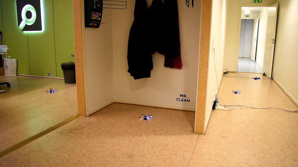
First of all, let’s check out the video
We are using our office for the demo and the Crazyflies are essentially flying a fixed trajectory from our meeting room, through the office and kitchen to finally land in the Arena. The Crazyflies are autonomous from the moment they take off and there is no communication with any external computer after that, all positioning is done on-board.
Implementation
The demo is mainly implemented in the Crazyflie as an app with a simple python script on an external machine to start it all. The app is identical in all the Crazyflies so the script tells them where to land and checks that all Crazyflies has found their position before they are started. Finally it tells them to take off one by one with a fixed delay in-between.
The Crazyflie app
When the Crazyflie boots up, the app is started and the first thing it does is to prepare by defining a trajectory in the High Level Commander as well as setting data for the Lighthouse base stations in the system. The app uses a couple of parameters for communication and at this point it is waiting for one of the parameters to be set by the python script.
When the parameter is set, the app uses the High Level Commander to take off and fly to the start point of the trajectory. At the starting point, it kicks off the trajectory and while the High Level Commander handles the flying, the app goes to sleep. When reaching the end of the trajectory, the app once more goes into action and directs the Crazyflie to land at a position set through parameters during the initialization phase.
We used a feature of the High Level Commander that is maybe not that well known but can be very useful to make the motion fluid. When the High Level Commander does a go_to for instance, it plans a trajectory from its current position/velocity/acceleration to the target position in one smooth motion. This can be used when transitioning from a go_to into a trajectory (or from go_to to go_to) by starting the trajectory a little bit too early and thus never stop at the end of the go_to, but “slide” directly into the trajectory. The same technique is used at the end of the trajectory to get out of the way faster to avoid being hit by the next Crazyflie in the swarm.
The trajectory
The main part of the flight is one trajectory handled by the High Level Commander. It is generated using the uav_trajectories project from whoenig. We defined a number of points we wanted the trajectory to pass through and the software generates a list of polynomials that can be used by the High Level Commander. The generated trajectory is passing through the points but as a part of the optimization process it also chooses some (unexpected) curves, but that could be fixed with some tweaking.
The trajectory is defined using absolute positions in a global coordinate system that spans the office.
Positioning
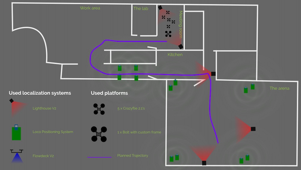
We used three different positioning systems for the demo: the Lighthouse (V2), the Loco Positioning system (TDoA3) and the Flow deck. Different areas of the flight space is covered by different system, either individually or overlapping. All decks are active all the time and pick up data when it is available, pushing it into the extended Kalman estimator.
In the meeting room, where we started, we used two Lighthouse V2 base stations which gave us a very precise position estimate (including yaw) and a good start. When the Crazyflies moved out into the office, they only relied on the Flowdeck and that worked fine even-though the errors potentially builds up over time.
When the Crazyflies turned around the corner into the hallway towards the kitchen, we saw that the errors some times were too large, either the position or yaw was off which caused the Crazyflies to hit a wall. To fix that, we added 4 LPS nodes in the hallway and this solved the problem. Note that all the 4 anchors are on the ground and that it is not enough to give the Crazyflie a good 3D position, but the distance sensor on the Flow deck provides Z-information and the overall result is good.
The corner when going from the kitchen into the Arena is pretty tight and again the build up of errors made it problematic to rely on the Flow deck only, so we added a lighthouse base station for extra help.
Finally, in the first part of the Arena, the LPS system has full 3D coverage and together with the Flow deck it is smooth sailing. About half way the Crazyflies started to pick up the Lighthouse system as well and we are now using data from all three systems at the same time.
Obviously we were using more than 2 basestations with the Lighthouse system and even though it is not officially supported, it worked with some care and manual labor. The geometry data was for instance manually tweaked to fit the global coordinate system.
The wall between the kitchen and the Arena is very thick and it is unlikely that UWB can go through it, but we still got LPS data from the Arena anchors occasionally. Our interpretation is that it must have been packets bouncing on the walls into the kitchen. The stray packets were picked up by the Crazyflies but since the Lighthouse base station provided a strong information source, the LPS packets did not cause any problems.
Firmware modifications
The firmware is essentially the stock crazyflie-firmware from Github, however we did make a few alterations though:
The maximum velocity of the PID controller was increased to make it possible to fly a bit faster and create a nicer demo.
The number of lighthouse base stations was increased
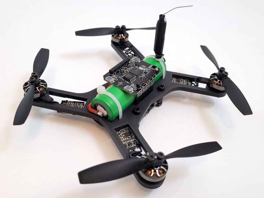
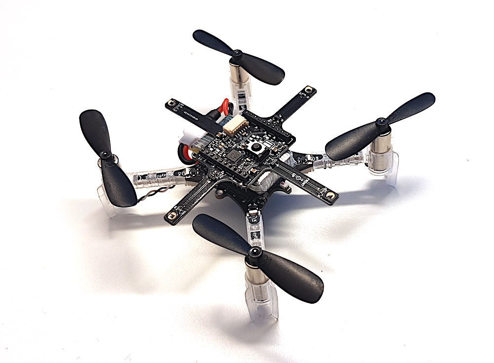
In the demo we used 5 x Crazyflie 2.1 and 1 x Bolt very similar to the Li-Ion Bolt we built recently. The difference is that this version used a 2-cell Li-Po and lower KV motors but the Li-Ion Bolt would have worked just as well.
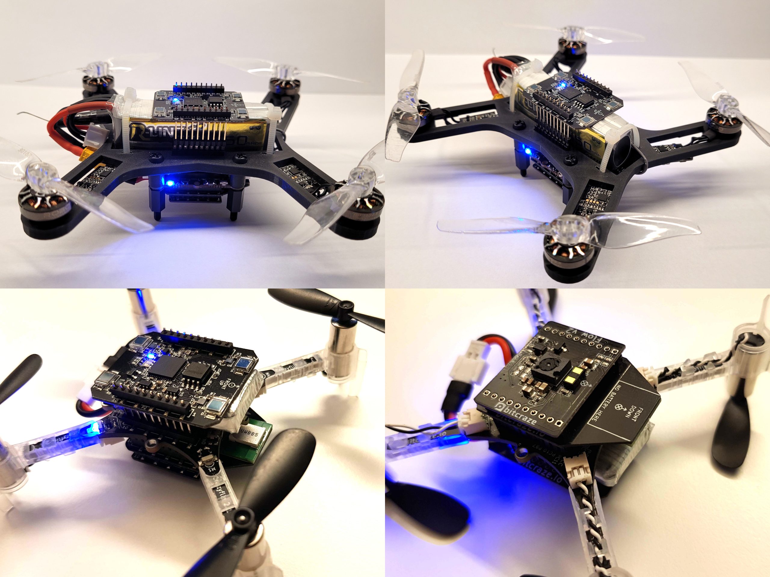
Hyperdemo drones and they configurations
To make all positioning to work at the same time we needed to add 3 decks, Lighthouse, Flow v2 and Loco-deck. On the Crazyflie 2.1 this fits if the extra long pin-headers are used and the Lighthouse is mounted on top and the Loco-deck underneath the Crazyflie 2.1 with the Flow v2 on the bottom. The same goes for the Bolt, but here we had to solder the extra long pin-header and the long pin-header together to make them long enough.
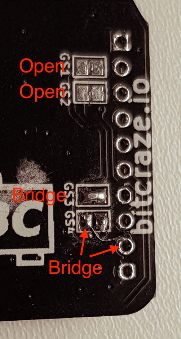
There is one catch though… the pin resources for the decks collide. With some patching of the loco-deck this can be mitigated by moving its IRQ to IO_2 using the solder-jumper. The RST needs to be moved to IO_4 which requires a small patch wire.
Also some FW configuration is needed which is added to the hyperdemo makefile:
The final weight for the Crazyflie 2.1 is on the heavy side and we quickly discover that fully charged batteries should be used or else the crash probability is increased a lot.
Conclusions
We’re happy we were able to set this demo up and that it was fairly straight forward. The whole setup of it was done in one or two days. The App layer is quite useful and we tend to use it quite often when trying out ideas, which we interpret as a good sign :-)
We are satisfied with the results and hope it will inspire some of you out there to push the limits even further!
Li-Ion batteries have packed more energy per gram for a long time compared to Li-Po batteries. The problem for UAV applications has been that Li-Ion can’t deliver enough current, something that is starting to change. Now there are cells that are supposed to be able to deliver 30-35A continuously in the 18650 series, at least according to the specs. Therefor we thought it was time to do some testing and decided to build a 1 cell Li-Ion drone using the Crazyflie Bolt as base.
Since a 18650 battery is 18mm in diameter and 65mm long, the size would affect the design but we still wanted to keep the drone small and lightweight. The battery is below 20mm wide which means we can run the deck connectors around it, that is nice. We chose to use our 3D printer to build the frame and use off the shelf ESCs, motors and props. After a couple of hours of research we selected 3″ propellers, 1202.5 11500kv motors and tiny 1-2s single ESCs for our first prototype.
Parts list:
1 x Custom designed 130mm 3D printed frame
1 x Crazyflie Bolt flight controller
4 x Eachine 3020 propeller (2xCW + 2xCCW)
4 x Flywoo ROBO RB 1202.5 11500 Kv motors
4 x Flash hobby 7A 1-2S ESC
1 x Li-Ion Sony 18650 VTC6 3000mAh 30A
Screws, anti vib. spacers, zipties, etc.
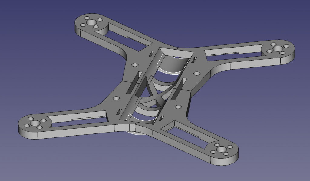
The custom designed frame was developed in iterations, and can still be much improved, but at this stage it is small, lightweight and rigid enough. We wanted the battery to be as central as possible while keeping it all compact.
Prototype frame designed in FreeCAD.
Assembly and tuning
The 3D printed frame came out quite well and weighed in at 13g. After soldering the bolt connectors to the ESCs, attaching motors and props, adjusting battery cable and soldering a XT30 to the Li-Ion battery it all weighed ~103g and then the battery is 45g of these. It feels quite heavy compared to the Crazyflie 2.1 and we had a lot of respect when we test flew it the first time. Before we took off we reduced the pitch and roll PID gains to roughly half and luckily it flew without problems and quite nicely. Well it sounds a lot but that is kind of expected. After increasing the gains a bit we felt quite pleased with:
This would be good enough for what we really wanted to try, the endurance with a Li-Ion battery. A quick measurement of the current consumption at hover, 5.8A, we estimated up to ~30 min flight time on a 3000mAh Li-Ion battery, wow, but first a real test…
Hover test
For the hover test we used lighthouse 2 which is starting to work quite well. We had to change the weight and thrust constants in estimator_kalman.c for the autonomous flight to work:
#define CRAZYFLIE_WEIGHT_grams (100.0f)

//thrust is thrust mapped for 65536 <==> 250 GRAMS!
#define CONTROL_TO_ACC (GRAVITY_MAGNITUDE*250.0f/CRAZYFLIE_WEIGHT_grams/65536.0f)
After doing that and creating a hover script that hovers at 0.5m height and was set to land when the voltage reached 3.0V. We leaned back with excitement, behind a safety net, and started the script… after 19 min it landed… good but not what we hoped for and quite far from the calculated 30 min. Maybe Li-Ion isn’t that good when it needs to provide more current…? A quick internet search and we could find that Li-Ion can run all the way down to 2.5V, but we have to stop at 3.0V because of electronics and loosing thrust, so we are missing quite a bit of energy… Further investigations are needed.
Lighthouse 2 flight test
As a final test we launched some flight scripts to fly in a square and in a spiral so we would get a feel for Lighthouse 2 + Bolt with PID controller combination. We think it turned out quite nicely, and this with almost no optimization effort:
Summary
Li-Ion felt like it could be a game changer when it comes to flight time but was not as promising as we hoped for. It doesn’t mean we can’t get there though. More research and development is required.
I am back from parental leave and during this time I tried not to think too much about Crazyflie-related things to get a little break. However, over time, while geeking around, I eventually ended-up back to Crazyflie and Crazyradio designing a new channel-hopping communication protocol. This will likely be the subject of a future blog post but for the time being I thought I could write a bit about how the current Crazyflie radio communication is working.
Protocol layers
Like Many protocols, the Crazyflie communication protocol is layered. This allows to plug different elements at each level. When it comes to a Crazyflie client talking to a Crazyflie over the radio, the layering looks as follow:
Services are high-level functionalities like log that allows to get values of Crazyflie variables at regular interval. At this level there is essencially an API with commands like addLogBlock.
CRTP is a protocol that encapsulates the commands for each sevices. It multiplexes packets on the link using port numbers, this is very similar to TCP/UDP port on a network, each service is listening and sending packet on a pre-specified port.
Finally the radio link only deals with raw packets. The role of the radio link is to deliver packets from the PC to the Crazyflie and vice-versa. At this level, we have many link implementations, the most used are the radio and the USB link but there also is a Serial link that uses the Crazyflie serial port.
Radio link
The radio link is currently implemented by the Crazyradio (PA) on the PC side and the Crazyflie on the other side. The Crazyradio uses a nordic semiconductor nRF24LU1 USB/Radio chip and the Crazyflie a nRF51822 MCU/Radio. This is importance since, while the nRF51 has a quite flexible radio, the nRF24 does use a standalone SPI radio that has most of the packet handling hard-coded to a protocol that nordic call Enhanced Shockburst (ESB).
The ESB protocol handles sending packet and receiving acknowledgement automatically. A packet is sent on a radio channel, using a 5 bytes address, and when this packet is received on the other side an acknowledgement is sent back using the same address on the same channel. Both the original packet and the acknowledgement can contain a payload.
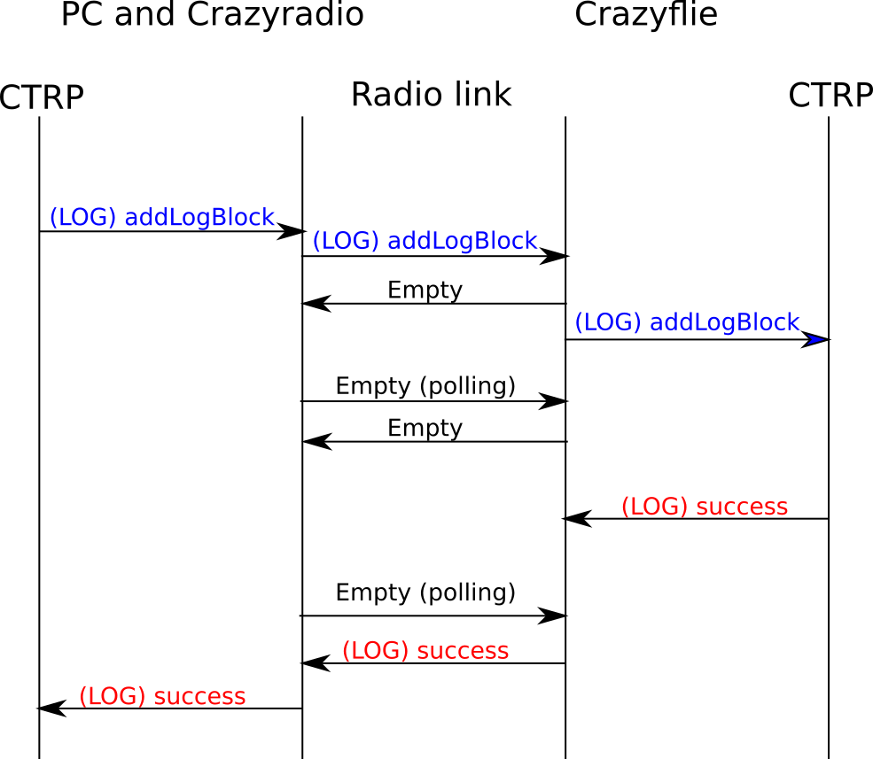
To implement a bi-directional radio link, the crazyradio is the one sending packets and the Crazyflies continuously listens and, when receiving a packet, sends back an ack. We do use the payload capabilities of both packet we send and of the ack to implement an uplink (PC->Crazyflie) and downlink (Crazyflie->PC) data link.
Of course, one problem with this setup is that while the PC can decide to send a packet at any moment, the Crazyflie needs to wait for the PC to send a packet to have a chance to send one back in an ACK. To make sure the Crazyflie has enough opportunity to send packets back, we are sending packets regular interval to the Crazyflie even if there is no packet to be sent. This polling allows to implement a continuous downlink.
The most important to see here is that the radio link gives to the upper layer, the CRTP layer, the illusion of a full duplex link. On the radio side this is implemented by polling regularly for downlink packets.
Communicating with multiple Crazyflies
In order to communicate with multiple Crazyflie, we just send packet to each Crazyflies one after each-other. This way we give equal chance for each Crazyflie to send back packets and doing so we divide the available bandwidth between them.
The main advantage of the polling protocol versus a more traditional P2P protocol where the Crazyflies would send when they want, is that when using polling the Crazyradio is the master and we can guarantee that we are not introducing any packet collision when we communicate.
Limitation and future
One major limitation of the current protocol is that it communicates on a single channel and requires the user to set manually channel and address for each Crazyflies. This means that the user has to tinker with parameters to find a good channel and has to manually handle all addressing.
Another limitation is that the polling is done over USB by python or, in case of ROS/Crazyswarm, in C++. This adds the USB latency to the equation and complexifies the client implementation.
I have been working on defining a new protocol that would be implemented efficiently in a Crazyradio and that would implement addressing and channel hopping. The idea is to get closer to a connection style more like bluetooth low energy where you do not have to care about channels and setting address, you just connect your device. Unlike BLE though, this protocol will be optimized for low latency. Stay tuned, we will likely talk about that more in future posts :-).
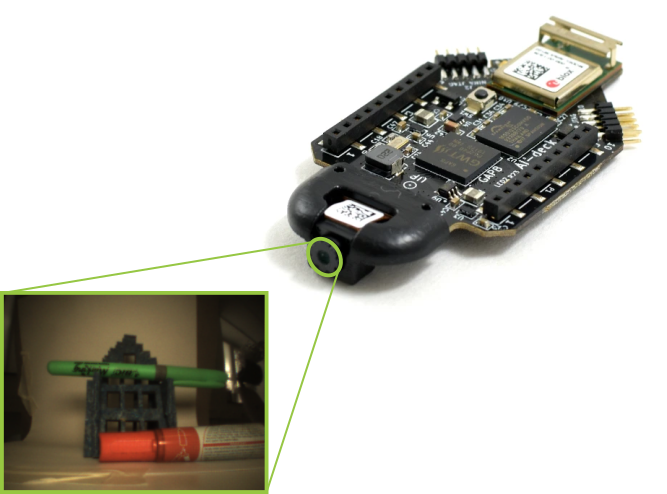
It has been about a month since the AI-deck became available in Early Access. Since then there are now quite a few of you that own an AI-deck yourself. A new development we would like to share: we thought before that we had selected a gray-scale image sensor. However, it came to our attention that the camera actually contains a color image sensor, which on second viewing of the video presented in this blogpost is pretty obvious in hindsight (thanks PULP project ETH Zurich for letting us know!).
A color image from the AI-deck
This came as a little surprise, but a color camera can also add some new possibilities, like making the Crazyflie follow a orange ball, or also train the CNNs incorporate color in their classification training as well. The only thing is that it will require an extra preprocessing task in order to retrieve the color image, which will be explained in the next section.
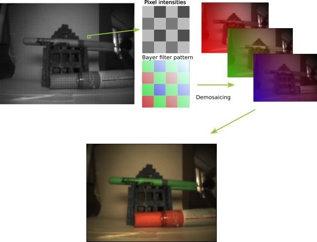
Demosaicing
Essentially all CMOS image sensors are gray-scale by definition. In order to retrieve color from a scene, manufacturers add a Bayer filter on top of the image sensor, so it filters out the red, green and blue on each pixels. This Color filter array does not need to be RGB, but all kinds of colors, but we will only talk about the Bayer filter. If the pattern of the filter is known, the pixels that related to a certain color will be interpolated with each-other in order to fill in the gaps in between. This process is called demosaicing and it creates the RGB channels that are converted to a color image.
Process of demosaicing with a Bayer filter
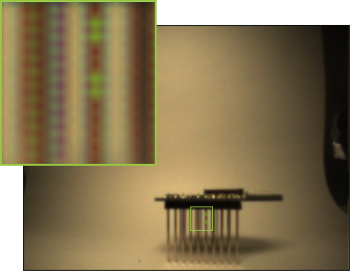
Currently we only implemented a simple nearest-neighbor interpolation scheme for demosaicing, which is fine for demonstration purposes, however is not the best technique out there. Such a simple interpolation is not very ‘edge and detail’ aware and can therefore cause artifacts, like these Moiré effects seen here below. Anyway, we are still experimenting how to get a better image and how to translate that to all the examples of the AI-deck example repository (see this issue if you would like to follow or take part in the discussion).
Moiré effect
So technically, once we have the color image, this can be converted to a gray-scale images which can be used for the examples as is. However, there is a reduction in quality since the full pixel resolution is not used for obtaining the full scale image. We are currently discussing if it would be useful to get the gray-scale version of this camera and make this available as well, so let us know if you would be interested!
Feedback and Early Access
Like we said before, there now quite a few of you out there that have an AI-deck in their procession. As it is in Early Access, the software part is still in full development. However, since we have not received any negative feedback of you, we believe that everything is fine and peachy!
Just kidding ;) we know that the AI-deck is quite a challenging deck to work with and we know for sure that many of you probably have questions or have something to say about working with it. Buying an Early Access product also comes with a little bit of responsibility. The more feedback we get from you guys, the more we can tailor the software and support to help you and others, thereby advancing the product forward and getting it out of the early access phase.
So please, let us know if you are having any trouble starting up by posting a thread on the forum (we have a special AI-deck group!). If there are any issues with the examples or the documentation of the AI-deck repo. We and also our collaborators at Greenwaves Technologies (from the GAP8 chip) are more than happy to help out. That is what we are here for :)
The AI-deck is now available in our online store! Super-edge-computing is now possible on your Crazyflie thanks to the GAP8 IoT application processor from GreenWaves Technologies. GAP8 delivers over 10 GOPS of compute power at exceptionally low power consumption enabling complex tasks such as path-finding and target following on the Crazyflie, consuming less than 0,1% of the total energy.
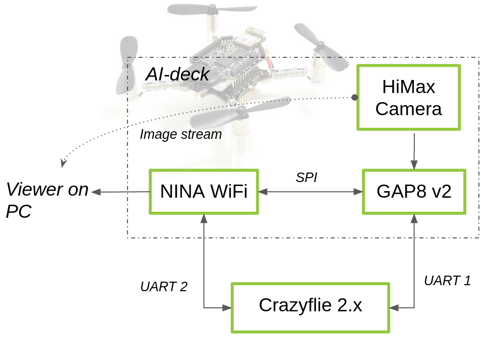
The AI-deck can host artificial intelligence-based workloads like Convolutional Neural Networks onboard. This will open up many research areas focusing on fully onboard autonomous navigation of tiny MAVs, like ETH Zurich’s PULP-Dronet. Moreover, there is also ESP32 WiFi connectivity with the possibility to stream the images to your personal computer.
We are happy that we managed to get everything ready so soon after our last update. Crazyflie AI-deck is in early access, which means the hardware design is now finalized and full support for building, running and debugging applications (including GreenWaves’ GAPflow tools for porting neural networks to GAP from TensorFlow) is available, however, limited examples of specific AI-deck applications have been developed so far. Read more about early access here. Even though there is still some work to be done, there are already some examples you can try out which we will explain in this blog post. Also, we aim to have all AI-decks pre-flashed with the WiFi streamer example so that you check out right away if your AI-deck is working.
Beware that you need an JTAG-enabled programmer/debugger in order to develop for the AI-deck!
Technical specifications
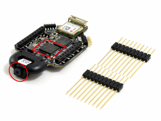
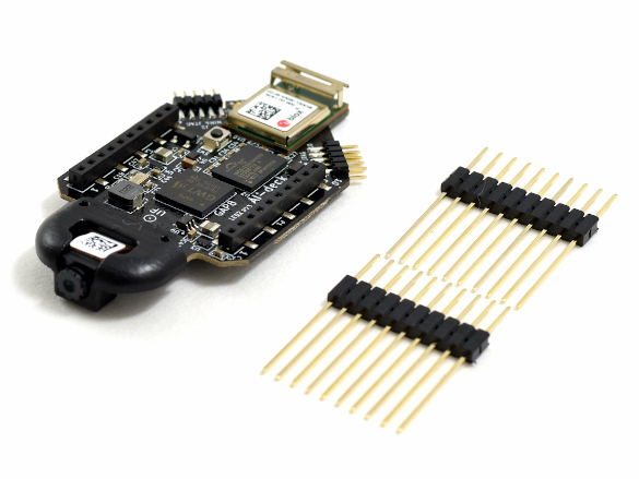
The AI-deck will come with two elongated male pin-headers, which enables the user to connect it to the Crazyflie with an additional deck. There are two 10 pin JTAG connectors soldered which enables connection with a JTAG-enabled programmer. This will be the main way to program the GAP8 chip and the ESP-based NINA module while it is still in early access.
Getting started
When you first receive your AI-deck, it should be flashed with a WiFi streamer example of the camera image stream. Once the AI-deck is powered up by the Crazyflie, it will automatically create a hotspot called ‘Bitcraze AI-deck Example’. In this repo in the folder named ‘NINA’ you will find a file called viewer.py. If you run this with python (preferably version 3), you will be able to see the camera image stream on your computer. This will confirm that your AI-deck is working.
Next step is to go to the docs folder of the AI-deck examples repository. Try out the WiFi demo and set up your development program with the getting-started guide. This guide contains links to the GAP-SDK documentation from GreenWaves Technologies. You can read more about the face detector example that we demonstrated in this blog post.
It has been a while since we have updated you all on the AI deck. The last full blogpost was in October, with some small updates here and there. It is not that we have not focused on it at all; on the contrary… this has been a high priority project for a while now. It is just quite a complex board with a lot of bells and whistles, which can be challenging to work with sometimes so early in development, something that our previous intern can definitely agree on. So therefore we rather wanted to wait until we were able to make sufficient progress before we gave you an update… and so we have!
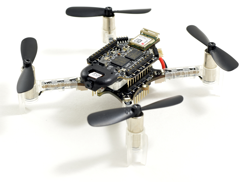
A Crazyflie 2.1 with the AI deck
Together with Greenwaves technologies we have been trying to get the SDK of the GAP8 chip on the AI deck stable enough for an early release. The latest release of the SDK (version 3.4) has proved itself to work with relative ease on the AI deck after extensive testing. Currently it is possible to use OpenOCD for flashing and debugging, and it supports most commonly available debuggers with a jtag connector. In the upcoming weeks both of Bitcraze and Greenwaves will test and try out all examples of the SDK on the AI deck to make sure that everything is still compatible. Also the documentation will be extended as well. As there is so much to document, it might be difficult to catch all of it. However, if you notify us and Greenwaves on anything that is missing once the AIdeck is out, that will help us out to catch the knowledge gaps.
The AI deck also contains the ESP-basedNINA module for establishing a WiFi connection. This enables the users to stream the video stream of the AI deck onto their computers, which will be quite an essential tool if they would like to generate their own image database for training the CNNs for the GAP8 (and it happens to also be quite practical for debugging by the way!). Currently it is required to set credentials of your local WiFi network and reflash the AI-deck to be able to connect and streaming the images, but we are working on turning the Nina into an access-point instead so no reflashing would be required. We hope that we will be able to implement this before the release.
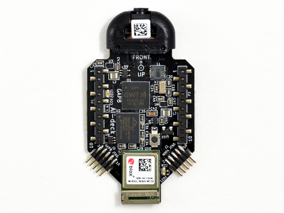
Top view of the AI deck
We are also trying out to adjust applications to make suitable of the AI deck. For instance, we have adapted Greenwaves’ face-detector example to use the image streamer instead of the display available on the GAPuino boards. You can see a video of the result here underneath. Beware that this face-detector is not based on a CNN but on HOG descriptors, so it only works in good conditions where the face is well lit. However, it is possible to train a CNN to detect faces in Tensorflow and flash this on the AI deck with the GAPflow framework as developed by Greenwaves. At Bitcraze we haven’t managed to try that out ourselves ( we are close to that though!) but at least this example is a nice demonstration of the AI deck’s abilities together with the WiFi-streamer. This example and more testing code can be found in our experimental repo here. For examples of GAPflow, please check out the examples/NNtool section of the GAP8 SDK.
For some reason WordPress has difficulty embedding the video that was supposed to be here, so please check https://youtu.be/0sHh2V6Cq-Q
Seeing how the development has been progressing, we will be comfortable to say that the AI deck could be ready for early release somewhere in the next month, so please keep an eye out on our website! We will continue to test the GAP SDK’s stability and we are very thankful for Greenwaves Technologies with their help so far. We will also work on getting-started guides in order to get acquainted with the AI deck, supplementing the already existing documentation about the GAP8 chip.
Even-though the AI deck will soon be ready for early release, this piece of hardware is not for the faint-hearted and embedded programming experience is a must. But keep in mind that the possibilities with the AI deck are huge, as it will be mean that super-edge-computing on a 30 gram flying platform will be available for anyone. It will all be worth it when you have your Crazyflie flying autonomously while being able to recognize its surroundings :)
In this blog-post we wanted to give you guys an overview of our running projects and a general update of the status of things! We got settled in our home-labs and are working on many projects in parallel. There are a lot of development happening at the moment, but the general feeling is that we do miss working with each other at our office! With our daily slack Bitcraze sync meetings and virtual fikapause (Swedish for coffee breaks), we try to substitute what we can. In the mean time, we are going on a roll with finishing all our goals we have set at our latest quarterly meeting, so here you can read about those developments.
AI-deck
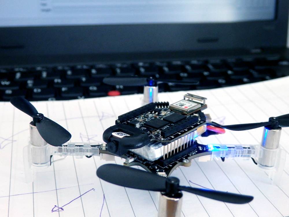
Crazyflie with AI-deck
The last time we gave an update about the AI-deck was in this blog post and in the final post of our intern Zhouxin. Building on his work, we are now refocusing on getting the AI-deck ready for early release. The last hurdle is mostly software wise on which we are considering several approaches together with the manufacturer of the Gap8 chip Greenwaves technologies. Currently we are preparing small testing functions as examples of the different elements of the AI-deck in our repo, which are all still in a very primarily phase.
Even though we still need some time to finalize the AI-deck’s early release, we will consider sending an early version of the AI-deck if you are willing to provide feedback while working with it. Please fill in the form and we will get back to you.
Lighthouse
We have made quite some progress on the development for the lighthouse V2. Kristoffer has been working hard from his homelab to get a seamless integration of both V1 and V2 in our firmware (check out this github issue for updates). Currently it is still very untested and very much in progress, however we do have a little preview for you to enjoy.
Crazyflie with LH basestation v2
Documentation
Right now, we are also doing a lot of revamping of the large web of documentation. Unfortunately this is a lot of work! As you noticed by now, we have added overview pages to guide the reader to the right information. We also have moved the tutorials to another part of the menu to avoid clutter on our website. In general we try to go through the repository docs to see if there is any information missing or outdated, however please let us know if you have encountered an error in any description or are missing crucial elements.
Our latest task is revamping the product pages as well, by putting all the necessary information about the hardware in just one place. Also, we are planning to make (video) tutorials soon about many elements of the Crazyflie and how to work with it. More about that later!
Production and Shipment
Production at our manufacturers in China are slowly starting up again. Although it is not yet back at full force, it does enable us to already start ordering to replenish our stock and to get started with finishing our test rigs. Moreover, we are also negotiating to resolve the propeller issue we mentioned earlier, but there is no update on that so far.
As mentioned in this blogpost, we are still shipping orders about twice a week. Both DHL and Fedex are functioning as normal, but we do notice that there is a delay of a few extra days on some deliveries. Please keep that in mind when ordering at our webshop.
We have mentioned the Active Marker deck in an earlier blog post, and are now happy to announce that it has been released and is available in our store.
Crazyflie with Active marker deck
By changing the passive, reflective markers to active, IR-LEDs, it is possible to improve the detection of markers in the cameras. There are two main reasons: the area of the marker is smaller and easier to separate from other markers close by, and the LEDs are emitting light and can be detected further away.
The deck has been developed in collaboration with Qualisys and together with the QTM system, it utilizes their Active Marker technology. An ID is assigned to each marker, and since the identity of each marker can be detected by the MoCap system, it is possible to estimate the full body pose of the Crazyflie without unique marker positions or known starting positions. IDs are easily assigned using the parameter sub system of the Crazyflie.
Even though the deck mainly is intended to be used with Qualisys MoCap systems, the LED markers can also be configured to be on or off which we hope might be useful in other applications as well.
This is it. The end of my internship. It feels strange to leave this unique office in a place called Malmö. My time spent here was more than just doing an assignment as part of a MSc. degree with the objective that I would gain working experience and contribute to a company.
My last day at the office of Bitcraze, Arnaud was already on parental leave
My time here gave me so much more. I have learned here a healthy way of thinking and problem solving which is part of the unique Bitcraze company culture. Next to that, it felt more like working with friends than just working with colleagues. Going to the office is a delight, as there is always humor, openness and honesty. I got to know everyone and enjoy the French, Swedish and Dutch-American hospitality and culture.
At this point you might think that I only have been drinking coffee and made sure that coffee in the office was not below level. Luckily that was not the case. I had the privilege to be the first user for a new deck. This deck has been in development for quite some time now and has been glossed over in some earlier blog posts. It is the yet to-be-released AI-Deck! At the moment the early-access AI-Decks are a delayed due to the COVID-19 virus. Bitcraze will update you on the blog when they know more.
My task within Bitcraze, in more detail, was to improve user friendliness of the AI-Deck by providing a framework for future users and at the same time to explore user friendliness of the whole ecosystem around the AI-Deck for an engineering student with beginner experience in embedded programming (e.g. me).
At the verge of giving the Crazyflie some AI capabilities, while being micromanaged.
So my mission began. A logical step was to see if the convolutional neural network from the PULP-DroNet project would run on the AI-Deck and fly with the Crazyflie, as the AI-Deck is an evolution of the PULP-Shield developed for this project. More information about this can be found here.
Unfortunately, this was not an easy feat as the PULP-DroNet project is using the pure version of the PULP SDK and an outdated autotiler. While the development partner for the AI-Deck, Greenwaves Technologies, uses the PULP SDK as a base with added functionalities in their SDK, which made it divert from the SDK used in the PULP-DroNet project.
Though, I was able to run the convolutional neural network in a simulated environment and compare this to the original DroNet that was implemented using Python and a Bebop. It was interesting to find out that the convolutional neural network of PULP-DroNet was behaving differently than the original DroNet in Python. There can be many explanations for this, but the main hypothesis is that this is caused by quantizing the network of PULP-DroNet from 32-bit floating point to 16-bit fixed point. In addition, the aforementioned network is trained on a larger dataset which included data created by a Himax camera.
A single Crazyflie obtained self-awareness and spun up a swarm of Crazyflies to gain world domination
While porting PULP-DroNet to the AI-Deck should be possible, the obstacles found along the way made it too troublesome and out of scope for my internship. So I moved on with the main objective, making a framework/example for the AI-Deck using the SDK provided by Greenwaves Technologies, which is called the GAP8 SDK. It contains a set of tools that should make the use of the AI-Deck easier, namely the NNTool and Autotiler tool. These tools make sure that you can automate the conversion of your neural network that is designed and trained in Python (Tensorflow and Keras) to a neural network code that can utilize the GAP8 functionalities.
My internship came to an end before I could overcome the last hurdle for a working example. To still bring this example to you, I have committed the doc/code I wrote and handed over the knowledge that I have accumulated throughout my internship when working with the AI-Deck and its environment to the capable minds of Kimberly and Tobias.
Along the way I have learned a lot about embedded programming and being a first product user. In addition with embedded programming and programming in general comes a different mindset than a conventional planning and deadline fixed mindset you get from university. With these valuable lessons in mind, I will be heading back to the TU Delft to start with my master thesis in either reinforcement learning for aircrafts or dense optical flow nets for quadcopters. Thank you Bitcraze for your time, experience and hospitality!