We are currently finishing production test design for a couple of expansion decks and we figured we never wrote about it and about the more general board production process. In this blog post we wanted to talk a bit about how we test boards in the productions phase, taking as an example the forthcoming active marker deck.
When finalizing an electronic board, we send to the manufacturer documentation that allows to manufacture & assemble a, hopefully, functional board. Although we assume that the individual components are in working order, the problem is that the assembling is not always perfect, so we need to check that everything we do is actually working,. This is what the production test is solving.
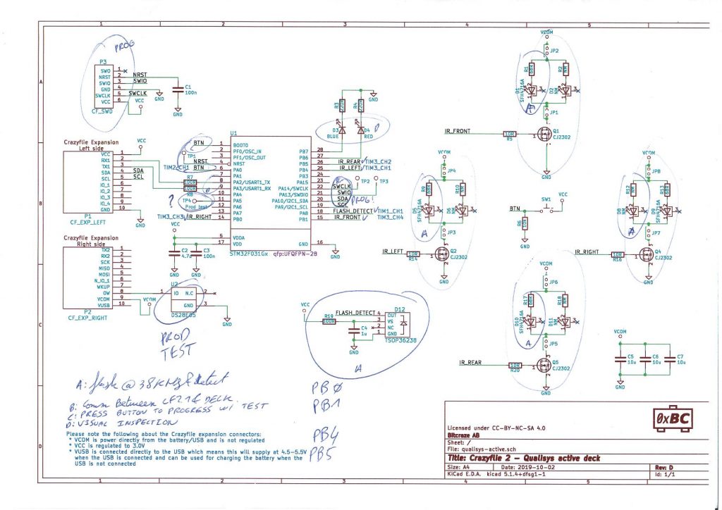
The first thing is to find out what to test, for that we need a strategy. The strategy we have been using is to test every step where we have modified or work on: for example we will test all the connections we have soldered in the manufacturing process. We will normally not test all the functionalities of ready-made module. For example, following this strategy, we will usually test all communication interface we have cabled, but we will not test all functionalities of a microcontroller we solder on the board, these are deemed to be already tested and working by the microcontroller manufacturer. This step usually end up with an annotated schematic:
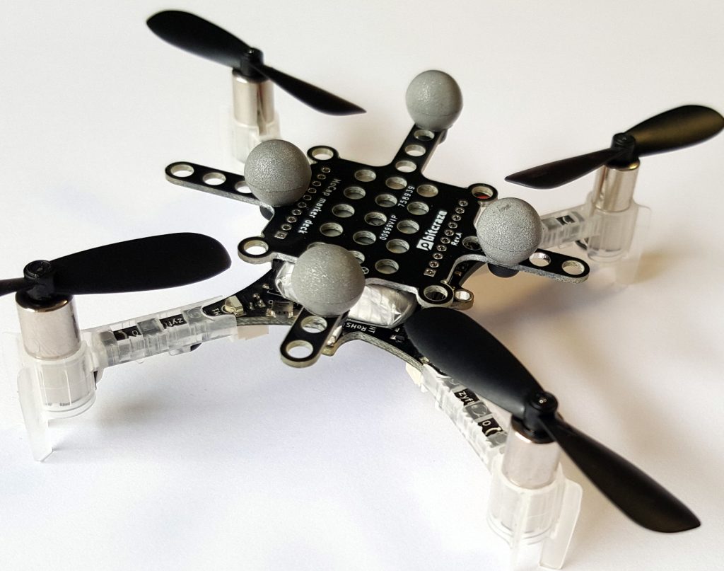
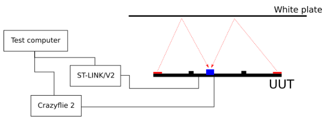
Once we know what to test and roughly how to test it, we document a test rig that will be able to run the tests automatically. Some tests are generic and applicable to all our boards, for example we do test voltages with a multi-meter on every board that has a regulator. Some tests are very board specific. For example, for the active marker deck we want to test IR LEDs and an IR detector, we define a test rig that has reflector to reflect the LED to the detector and we will use the onboard detector to test the LEDs:
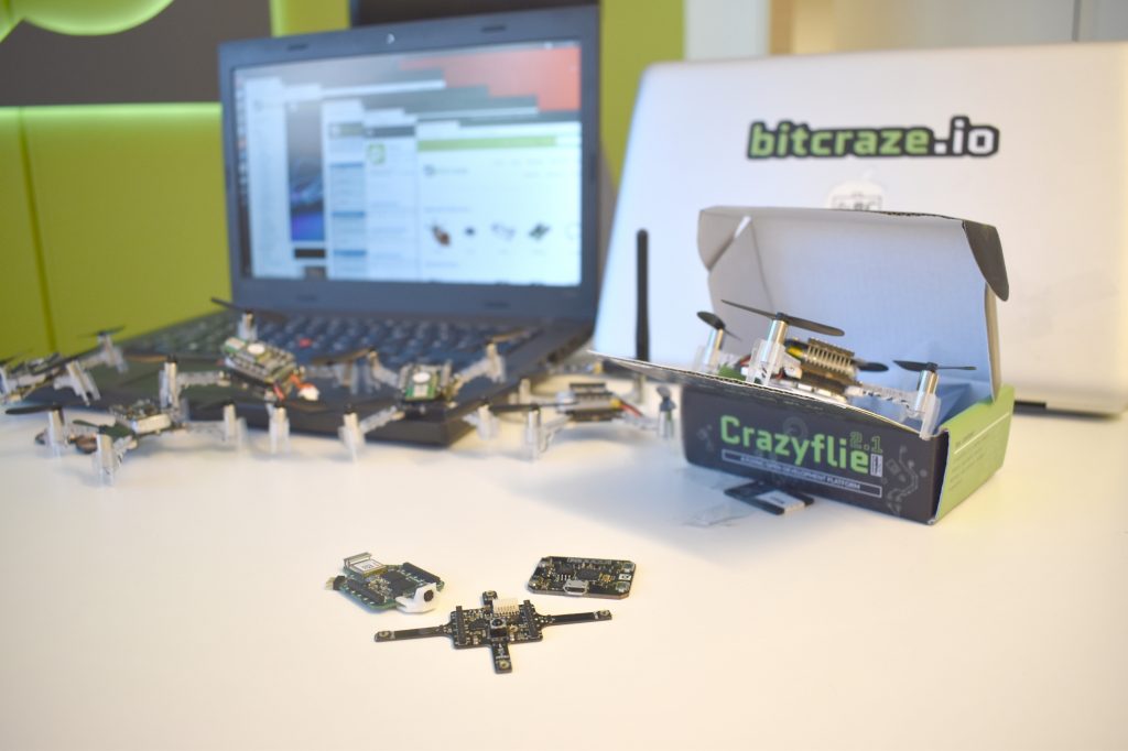
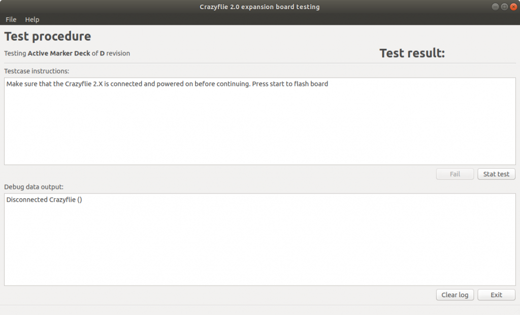
We are normally using a Crazyflie on all our test rig, since it is usually possible to test all functionality from the deck port. We also try as much as possible to integrate the test software into the real software. For the active marker deck it meant adding 38KHz modulated output mode to the LEDs in order to emit a signal detectable by the detector, which will make it to the final firmware. Finally, we have a test software, running on the test computer, that uses the Crazyflie python lib to talk to the Crazyflie and run the test. The last step of all the test is to write the deck One Wire identification memory so that it can be detected by a Crazyflie.
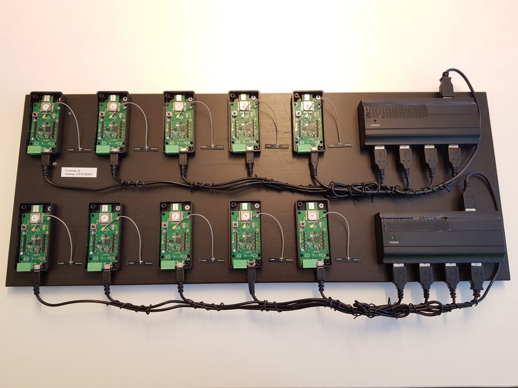
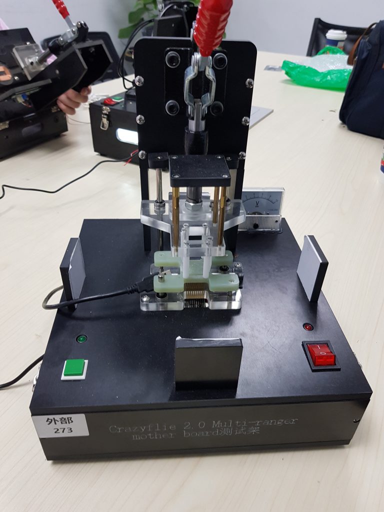
From these specification, the manufacturer can then build a test rig and start testing boards, non-passing board will be re-worked until they pass or discarded.
What we have learned in our years at Bitcraze is that testing phase is the most important part of the development process of PCB. Therefore, the earliest we already start thinking about the production tests in the board design, the more smooth the final phase of production of our new products will be.