We’ve been seeing an increase in the demand for a “programmable drone”, where users can easily give simple commands though scripting and the Crazyflie 2.0 following them. In order for this to work well you need a closed-loop control, i.e you need a reference system to see how you’re moving. Previously this was only possible using external camera systems or bulky on-board cameras. But a while ago we released the Flow deck which solves this problem. Thanks to the mouse-like sensor the deck contains it enables the Crazyflie 2.0 to see how it’s moving along the floor. Suddenly it’s possible to give commands like “move 1 m forward” or “fly in a clock wise circle with the radius of 1 m”.
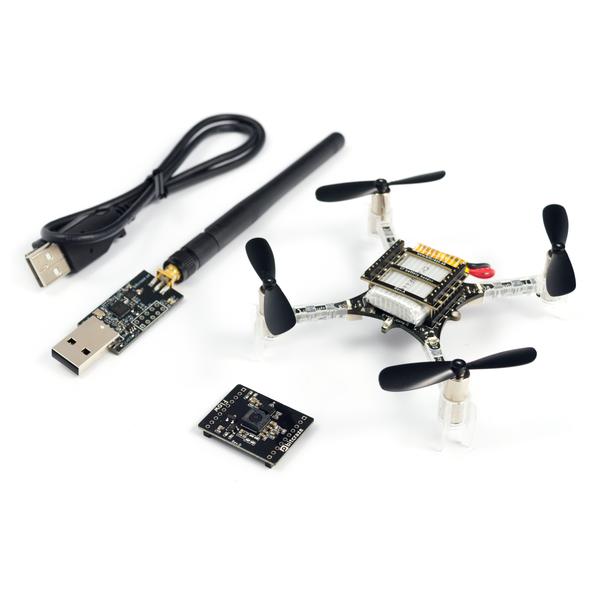
To make it easier for users to pick out the parts needed we’ve put together a discounted STEM drone bundle. It contains all the parts needed for scripting the flight. If you have a gamed-pad or a Bluetooth LE enabled phone you can of course fly it manually as well :-)
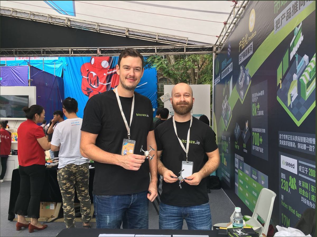
So we are now back in the cold and dark Sweden after about a weeks visit to a warm and nice Shenzhen, China. Every time we go there something major has happened. When we visited last time, about a year ago, cash was king. Now apparently payments are done with QR codes, even in small lunch restaurants. And I was kind of proud about the BankID and Swish payments we have here is Sweden, until now… Another observation we did was that there are now a lot of colorful rental bikes which can be found about everywhere and which can be rented for around 1 RMB/hour. A great way of resource sharing and pushing Eco-friendly transportation. It has it downside though as piles of bikes could be commonly found and e.g. written about by theguardian.
Aside from the above observations the Maker Faire Shenzhen was one of the reasons we came to visit. As Shenzhen is called the “the silicon valley for hardware” we had pretty high expectations when coming to the Maker Faire. Even though it was a great Faire it did not really reach our high expectations but it is growing fast and I’m pretty sure in a couple of years it is the Maker Faire to be at. A quick summarize, robotics was one of the top categories of products on the faire. 3D printers which are popular on European and US faires was not that common which surprised us. Now let the pictures do the talking:
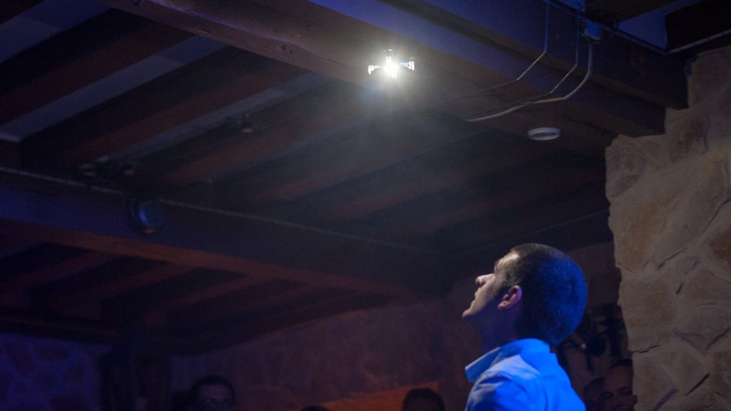
We exhibited on the faire sharing booth with Seeedstudio where we showed an autonomous sequence on top of a table using the flow deck. By pressing a button, the Crazyflie 2.0 would take of, fly in a circle, come back and land roughly in the same spot. It was a very engaging demo catching many peoples attention and especially the kids. The kids constantly wanted to press the button and interact with the Crazyflie.
All the interaction made us very happy and next time we will try to add the obstacle avoidance deck to make it even more engaging.
Unfortunately the Crazyradio PA is out of stock in our store and is estimated back around December 1. Until then please checkout our distributors for availability.
A few weeks ago we wrote about a new prototype that we call “the obstacle avoidance deck”. Basically it’s a deck fitted with multiple VL53L0x ToF distance sensors that measures the distance front/back, right/left and up of the Crazyflie 2.0. Combined with the Flow deck this gives you an X/Y/Z robot that you can program fly around avoiding obstacles which doesn’t need any external positioning system.
After implementing firmware support for the deck (see #253 and #254) we’ve finally had a chance to do some initial testing, see the video below. In the current implementation we’re doing the measurements in the firmware but using the logging framework to get all the distances into a Python script which does the movement control. Since we have the Flow deck attached we can control the Crazyflie 2.0 in velocity mode, which means we can say things like “Go forward with 0.5 m/s until the forward sensor shows a distance lower than 50cm” or “Go forward 1 m/s for 1s and rotate to measure the distance to all objects”. Since there’s no real-time requirements we can move the complexity of the algorithm from the firmware into external scripting which makes it a lot easier to develop. Now we’re really eager to start setting up obstacle courses and time how fast we can move though them :-)
The results from the testing shows that our two main concerns aren’t an issue: The sensors doesn’t seem to interfere with each other and we can sample them all at high-enough frequency without occupying the bus too heavily (currently we’re doing 20Hz). The next step is figuring out the requirements (i.e how many VL53L0x sensors are needed, do we really need the back one?) and a mechanical solution for attaching the sensors in production. If there’s any feedback let us know now and we’ll try to get it into the design. Also, we really need a new name for the board. Any suggestions?
A long time ago we got a request for a bright LED deck from a community member. When working with high powered leds heat becomes a problem that needs to be taken into account. From the community member we got suggestions of using one of the luxeon rebel leds and so we did. We designed a prototype pretty quickly but also realized that it is a bit harder than we first thought. If using a simple control scheme such as PWM and a mosfet the circuit is simple but brightness will be effected by battery voltage. Using a dedicated LED driver the brightness would be stable but the circuit more complicated and expensive. Trying to list the pros and cons:
MOSFET
+ Low complexity
+ Low cost
+ High efficiency
– varying brightness depending on battery voltage
– Might stress LED (could be solved with low ohm resistor)
LED driver
+ Stable brightness
+ Not as high efficiency (~80%)
– Higher cost
– Higher complexity
We ended up trying booth. The LED driver design failed due to that the battery voltage needed to be lower than the LED voltage + schottky and it is just in the middle. The PWM design half failed since the LED anode and cathode was swapped in the design but was possible to patch afterward. So at least we got something up and running.
The effect is very nice and it is what we used for the wedding show. The question now is, is this something we should finish and put in the store?
At any given time we have a bunch of deck ideas floating around. Some of them might not be doable (or very hard), but still fun to discuss. Other we just never get around to since we’re always pressed for time. The “obstacle avoidance” deck is one of the latter ones.
The idea with the “obstacle avoidance” deck (current working name in lack of imagination) is to mount one of the VL53L0x ToF distance sensors, the same we have on the Z-ranger and the Flow deck, in each direction. This would allow you to keep a distance to the ground, avoid the walls (or any other obstacles you might fly into) and also keep away from the ceiling. Basically you could do a “turtle bot” that just flies around randomly without crashing. Another fun idea we’ve been discussing is being able to SLAM the room you’re flying in. If you can keep track of how you are moving around (with the Flow deck, Loco positioning system or any other means) while you’re measuring the distance on all sides you could make a map of the room.
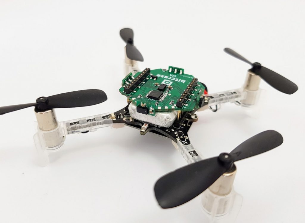
After discussing this on and off for a some time, mainly focusing on mechanical and production issues of the design, we decided to just try out the concept with a simple prototype. The prototype, named “OA”, has daughter boards with VL53L0x sensors mounted front/back, left/right as well as one sensor facing up. It’s designed to be mounted on the top of the Crazyflie 2.0 and combined with the Flow deck which will give relative movement and also the sixth direction, distance to the floor. One of the issues with the design is that all the VL53L0x sensors are on the same I2C bus with the same address. To work around this the sensor has a nifty feature where you can re-program the I2C address. For this to work you need to release the reset of the sensors one by one: release the first reset, reprogram the address and then release the reset of the next sensor. The reset for the VL53L0x is not cabled on the Flow deck, so this is the first to be re-programmed. Then the reset will be released one-by-one for the sensors on the OA deck. In order to control the reset pins on the deck there’s a 8bit I2C GPIO expander. The reason for the GPIO expander is to use as few GPIOs on the deck connector as possible to keep the compatibility with other decks high. For instance the deck will work fine with the Loco positioning deck.
The goal with the prototype is to try out the concept of the deck and to see if it’s feasible. A few of the things we need to sort out is:
Mechanical solution for side senors (front, back, left and right)
Interference between sensors
Update rate when we have 6 sensors on the same bus which we might have to run one-by-one to avoid interference
The current status is that we’ve verified the electronics and written the I2C GPIO expander drivers to test all the sensors. The next step is to work on a new VL53L0x driver to allow multiple sensors running at the same time, which will force some refactoring of the firmware. Once we’ve made some more progress we’ll do another post and report the results. If you have any feedback on the design/concept or have any ideas of what the deck could be useful for, don’t hesitate to drop a comment below.
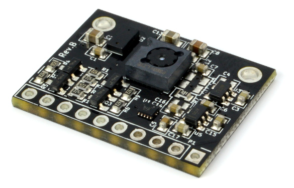
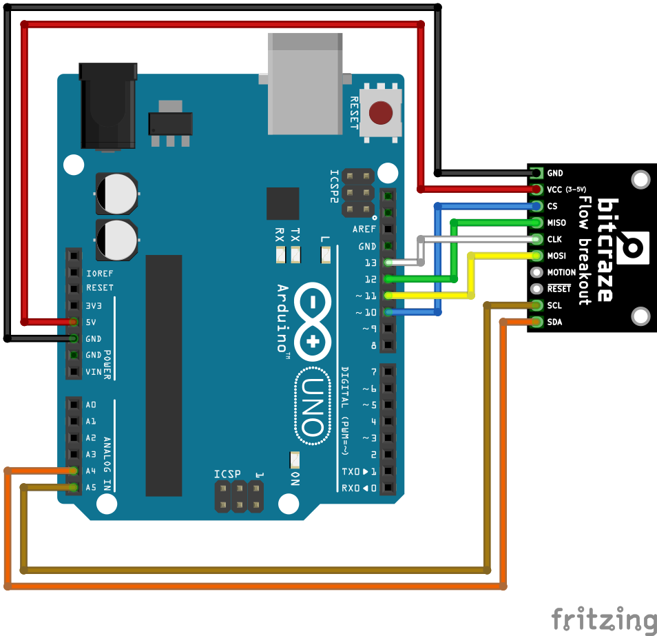
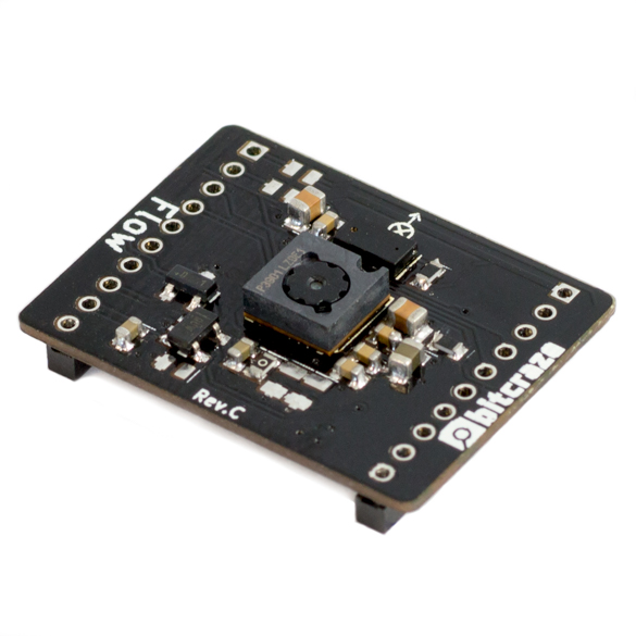
Last week we released the Flow deck, it enables you to get really stable autonomous flight with the Crazyflie without requiring an external positioning system. We have been lucky to get access to the brand new Pixart PMW3901 optical flow sensor, the core of the Flow deck, very early and we wanted to bring this awesome functionality to everyone, including those without a Crazyflie. The solution is the Flow breakout board, it enables anyone to use this new optical flow sensor for any kind of motion tracking.
The flow breakout contains a PMW3901 optical flow sensor and a VL53L0x time of flight ranging sensor, the same sensors that are mounted on the flow deck. We have also added voltage translation logic that allows you to use the flow breakout with a system voltage of 3 to 5V that makes it possible to use it directly with any Arduino board and most embedded system. Further more we have written an Arduino driver for the PMW3901 optical flow sensor to make it easy to use the breakout deck. For the VL53L0x there are already a couple of drivers available out there.
The flow breakout is currently being manufactured and will be available in our shop in a couple of weeks. If you want to be notified of the Flow breakout board availability, please sign up in the shop or follow us on twitter.
There have been a few requests from the community for a brushless Crazyflie and we blogged about a prototype we are working on a few weeks ago. The most common reason for wanting brushless motors is to be able to carry more load, in most cases a camera. A camera could be used for FPV flying or open up various image processing use cases like understanding the would around the drone using SLAM. Image processing on-board requires quite a lot of processing power and the CPU in the Crazyflie could not handle that, so more processing power would be required for a scenario like that. It is summer time (with a slight touch of play time) so we wanted to see what we could do with the CF Rzr and if it would be a useful platform for these types of applications. We hope that we might get some insights on the way as well.
We set the goal to try to add a camera, a small “computer”, the Flow deck for assisted flying, FPV capabilities and support for a standard RC controller.
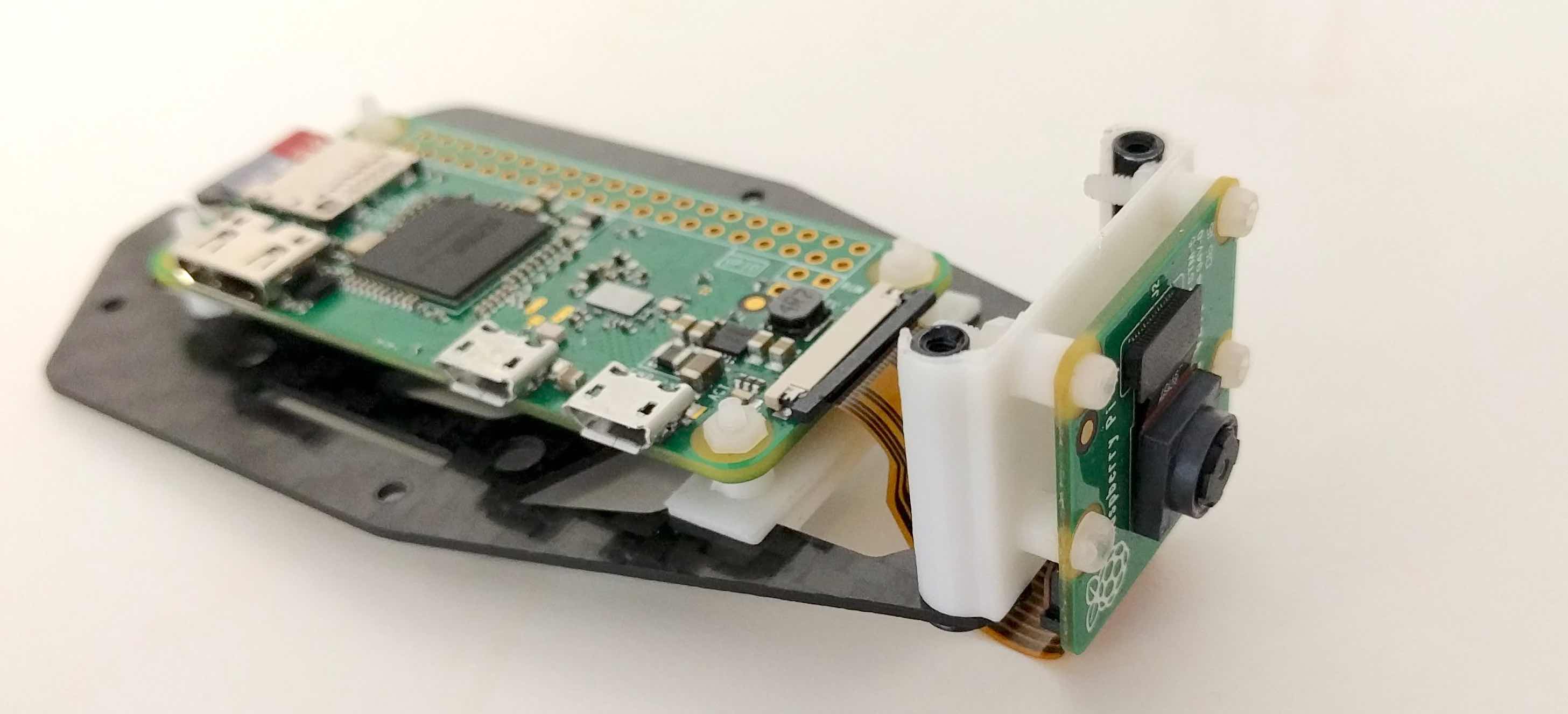
We chose the Raspberry pi zero-w in order to get video processing and video streaming from the quad as well as more computing power. The Raspberry pi zero is not the most powerful board our there but it has a couple of advantage for our prototype:
It has a readily available, good quality camera and good software support for it
It has an analog video output and hardware streaming support, which means that the quad could be flown FPV using the Raspberry pi camera
It has hardware JPEG and H264 encoders that will enable us to save and stream images and videos if we want to
Raspberry pi and camera mounted on the top part of the frame
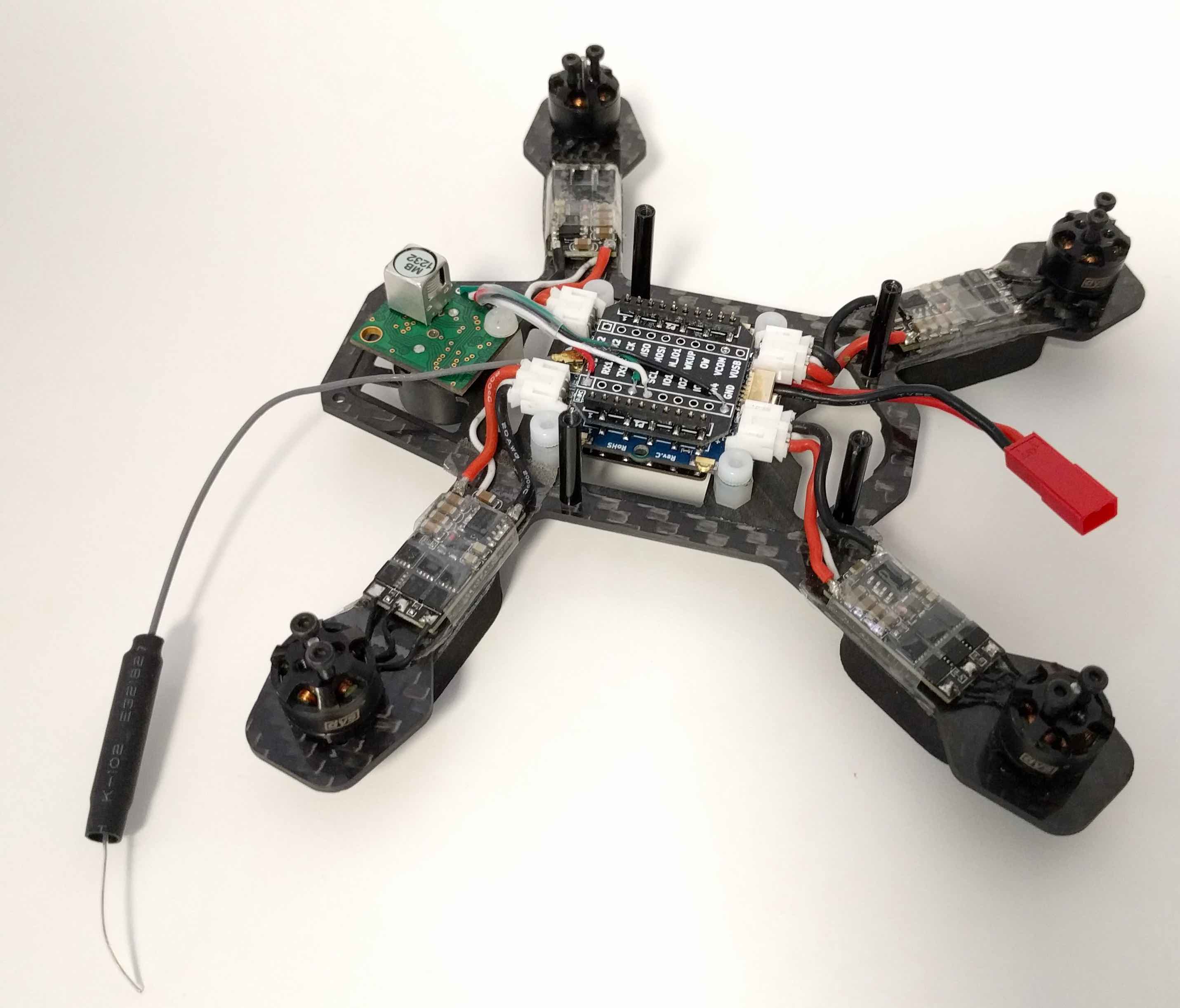
For assisted flight and improved stability, the XY-part of the Flow deck works fine outdoors but the laser height sensor on the deck has a maximum limit of 1-2 meters, and further more it does not go well with direct sunlight. We decided to add an ultrasound sonar distance sensor to measure the height instead. The ultrasound sonar connects via I2C and was simply soldered to a breakout deck that plugs into the CF Rzr.
Crazyflie Rzr with ultrasonic sonar, breakout deck and flow deck mounted on the lower part of the frame
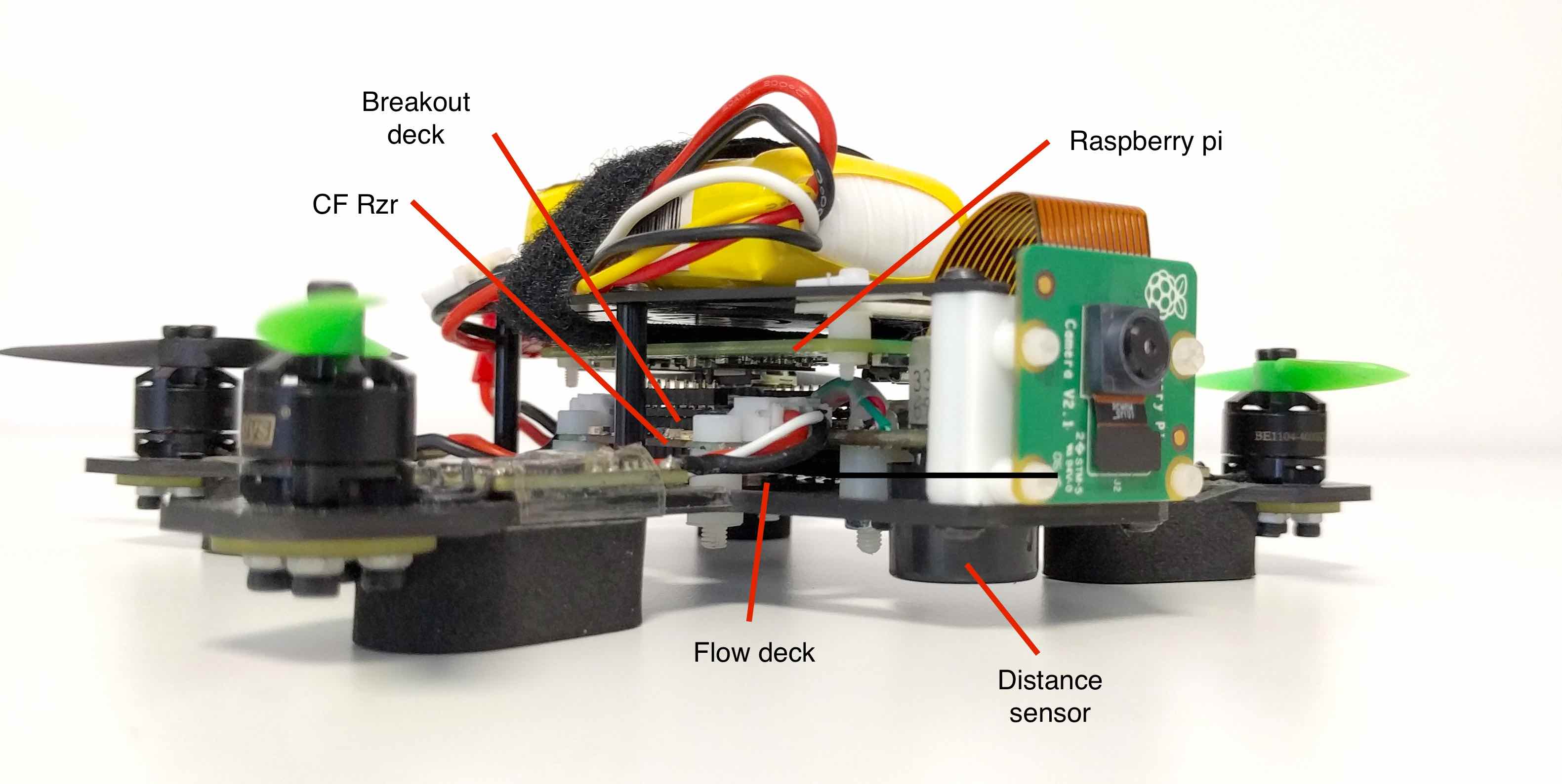
The first step is to see if we can physically fit everything on the frame. With some 3D printed mounts for the camera and the Raspberry pi, we think it starts to look pretty good. Next step will be to squeeze in the FPV video transmitter board, the RC receiver board and finally connect everything together.
The current setup with everything mounted
We are far from done but it is a good start, and it is fun.
We are pleased to announce the release of a new expansion deck for Crazyflie 2.0: the Flow deck. The flow deck is a new expansion board for Crazyflie 2.0 that contains an optical flow sensor from Pixart and a ranging sensor. These two sensors allows the Crazyflie to understand how it is moving above the floor and using this information the Crazyflie can fly itself.
The Flow deck can be used for manual flight where it allows to super easily fly the Crazyflie: if you realease all joystick the Crazyflie just stays there and hovers! The flow deck is even more interesting when used in combination with scripting: it is now possible to script the Crazyflie movement to achieve autonomous flight without needing any external positioning system.
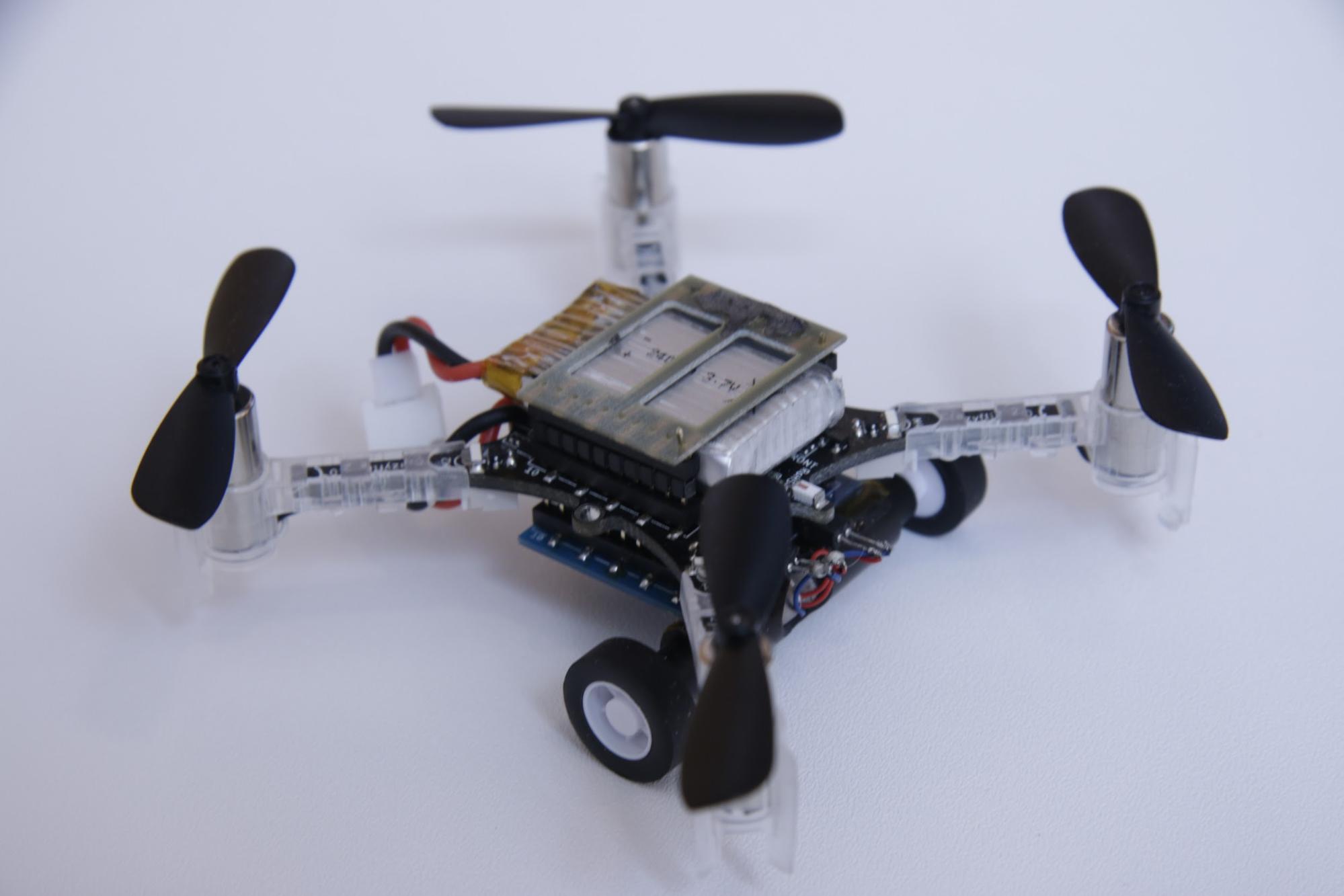
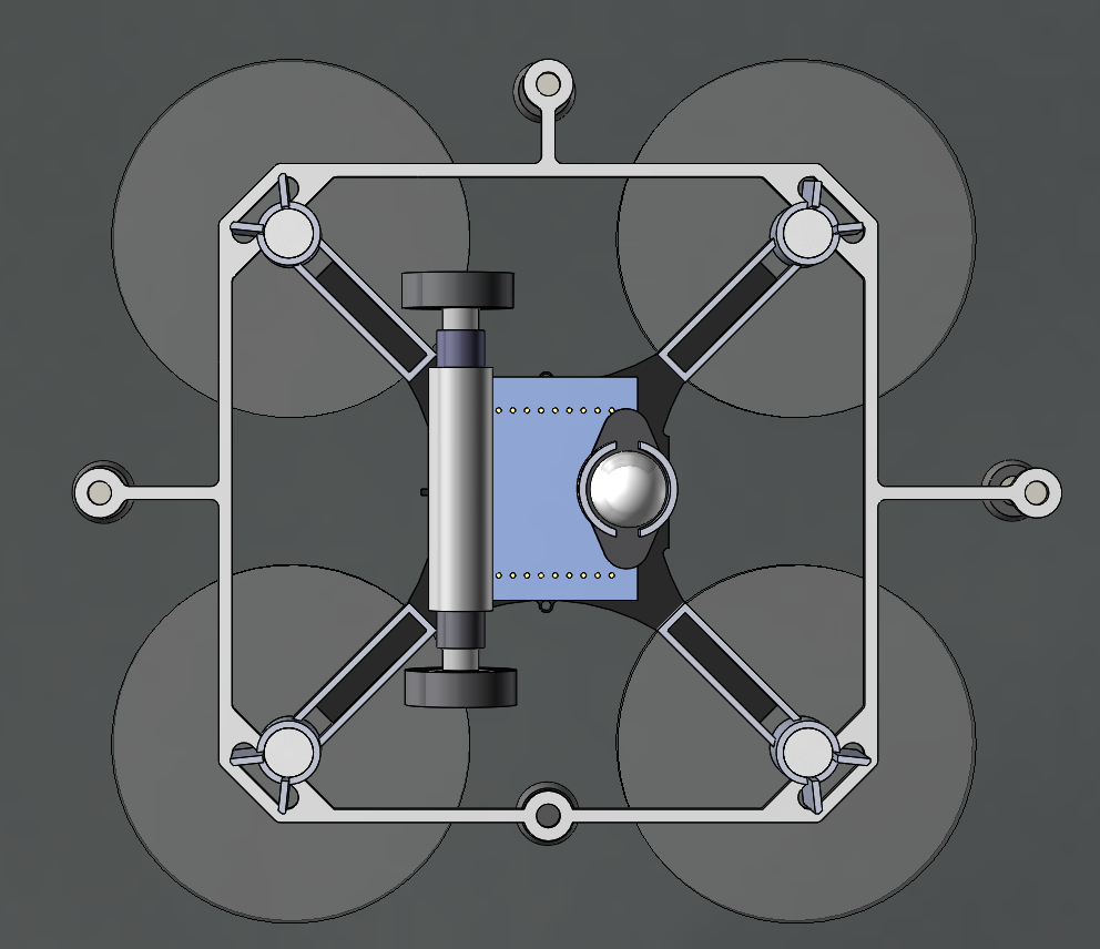
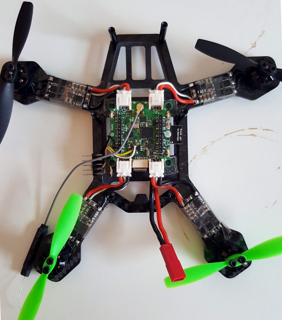
Robots that can both fly and drive – in particular wheeled drones – are actually somewhat of a rarity in robotics research. Although there are several interesting examples in the literature, most of them involve creative ways of repurposing the wings or propellers of a flying robot to get it to move on the ground. Since we wanted to test multi-robot algorithms, we needed a robot that would be robust, safe, and easy to control – not necessarily advanced or clever. We decided to put an independent driving mechanism on the bottom of a quadcopter, and it turns out that the Crazyflie 2.0 was the perfect platform for us. The Crazyflie is easily obtainable, safe, and (we can certify ourselves) very robust. Moreover, since it is open-source and fully programmable, we were able to easily modify the Crazyflie to fit our needs. Our final design with the wheel deck is shown below.
A photo of the Crazyflie 2.0 with the wheel deck.
A model of the Crazyflie 2.0 with the wheel deck from the bottom
The wheel deck consists of a PCB with a motor driver; two small motors mounted in a carbon fiber tube epoxied onto the PCB; and a passive ball caster in the back. We were able to interface our PCB with the pins on the Crazyflie so that we could use the Crazyflie to control the motors (the code is available at https://github.com/braraki/crazyflie-firmware). We added new parameters to the Crazyflie to control wheel speed, which, in retrospect, was not a good decision, since we found that it was difficult to update the parameters at a high enough rate to control the wheels well. We should have used the Crazyflie RealTime Protocol (CRTP) to send custom data packages to the Crazyflie, but that will have to be a project for another day.
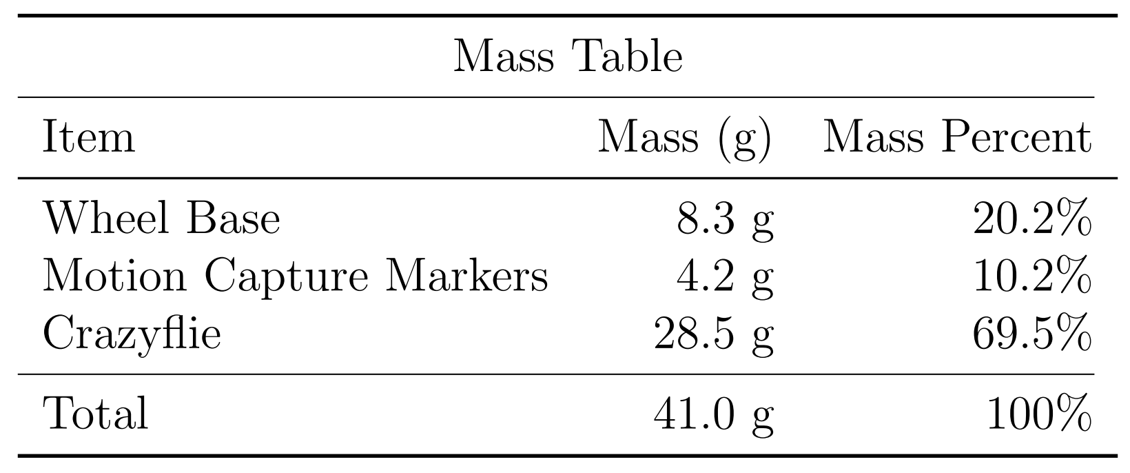
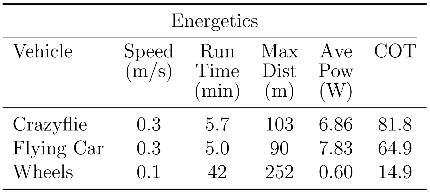
The table below shows the mass balance of our miniature ‘flying car.’ The wheels added 8.3g and the motion capture markers (we used a Vicon system to track the quads) added 4.2g. So overall the Crazyflie was able to carry 12.5g, or ~44% of its body weight, and still fly pretty well.
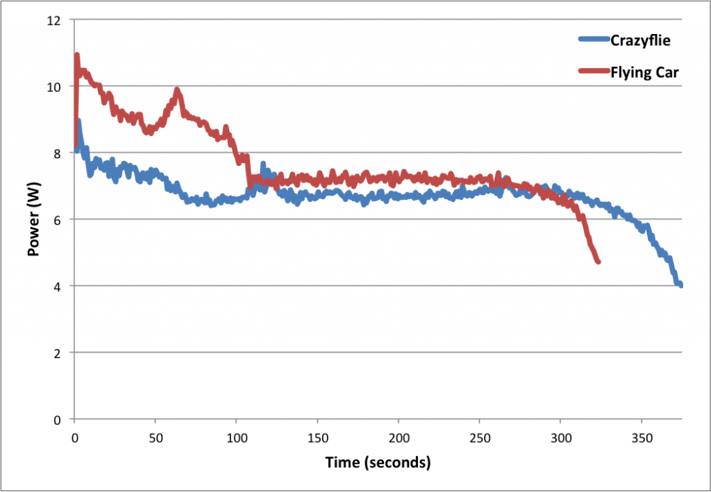
Next we measured the power consumption of the Crazyflie and the ‘Flying Car.’ As you can see in the graph below, the additional mass of the wheels reduced total flight time from 5.7 minutes to 5.0 minutes, a 42-second or 12.3% reduction.
Power consumption of the Crazyflie vs. the ‘Flying Car’
The table below shows more comparisons between flying without wheels, flying with wheels, and driving. The main takeaways are that driving is much more efficient than flying (in the case of quadcopter flight) and that adding wheels to the Crazyflie does not actually reduce flying performance very much (and in fact increases efficiency when measured using the ‘cost of transport’ metric, which factors in mass). These facts were very important for our planning algorithms, since the tradeoff between energy and speed is the main factor in deciding when to fly (fast but energy-inefficient) versus drive (slow but energy-efficient).
Controlling 8 Crazyflies at once was a challenge. The great work by the USC ACT Lab (J. A. Preiss, W. Hönig, G. S. Sukhatme, and N. Ayanian. “Crazyswarm: A Large Nano-Quadcopter Swarm,” ICRA 2017. https://github.com/USC-ACTLab/crazyswarm) has made our minor effort in this field obsolete, but I will describe our work briefly. We used the crazyflie_ros package, maintained by Wolfgang Hönig from the USC ACT Lab, to interface with the Crazyflies. Unfortunately, we found that a single Crazyradio could communicate with only 2 Crazyflies at a time using our methods, so we had to use 4 Crazyradios, and we had to make a ROS node that switched between the 4 radios rapidly to send commands. It was not ideal at all – moreover, we had to design 8 unique Vicon marker configurations, which was a challenge given the small size of the Crazyflies. In the end, we got our system to work, but the new Crazyswarm framework from the ACT Lab should enable much more impressive demos in the future (as has already been done in their ICRA paper and by the Robust Adaptive Systems Lab at Carnegie Mellon, which they described in their blog post here).
We used two controllers, an air and a ground controller. The ground controller was a simple pure pursuit controller that followed waypoints on ground paths. The differentially steered driving mechanism made ground control blissfully simple. The main challenge we faced was maximizing the rate at which we could send commands to the wheels via the parameter framework. For aerial control, we used simple PID controllers to make the quads follow waypoints. Although the wheel deck shifted the center of mass of the Crazyflie, giving it a tendency to slowly spin in midair, overall the system worked well given its simplicity.
Once we had the design and control of the flying cars figured out, we were able to test our path planning algorithms on them. You can see in the video below that our vehicles were able to faithfully follow the simulation and that they transitioned from flying to driving when necessary.
Our work had two goals. One was to show that multi-robot path planning algorithms can be adapted to work for vehicles that can both fly and drive to minimize energy consumption and time. The second goal was to showcase the utility of flying-and-driving vehicles. We were able to achieve these goals in our paper thanks in part to the ease of use and versatility of the Crazyflie 2.0.
For a while now we have been selling the BigQuad deck which makes it possible to transform the CF2 to control a bigger sized drone. It does so by becoming the quadrotor control board, controlling external brushless motor controllers, which allows to scale up the size. This can be very convenient when trying out/developing new things as it first can be tested on the small CF2 and later scaled up by attaching it to a bigger quad. However for a more permanent setup it is a bit bulky, so we have been playing around a bit and designed something in the middle. The result is a stand alone control board targeting quads around 0.1 – 0.5kg.
We call it the CF-RZR as it is inspired by the smaller sized racers with some fundamental differences. It is designed with a higher level of autonomous functionality in mind and being easy to repair while still being fully compatible with the CF2 firmware and decks. Listing the biggest features of the current prototype:
Fully compatible with the CF2 firmware, expansion decks as well as radio.
Connectors to attach motor controllers (still possible to solder though) so it is easy to build and repair.
Power distributions built into controller board. (Max ~8A per motor controller though)
Motor controllers can be switched of by the system so the system can go into deep sleep and consume around 50uA.
Voltage input 1S-4S (3V to 17V)
Standard mounting (M3 mounting holes placed 30.5mm square)
External antenna for increased range
To summarize, the strength of the CF2 but in a little bit bigger package :-). Last week we got a chance to test fly it for the first time. We used a off the shelf racer frame, ESC and motors. At first it did not fly that well at all but after some PID tuning it became pretty stable and we had a lot of fun :-).
We would love your feedback, good/bad idea, what do you like/dislike etc!