One of the goals during this project has been to only use open-source tools for development. The main incentive for this is that we want everyone to be able to take part in the development and look at the all the parts of it once it has has been released. Also it was a great opportunity to see how far we could push open source free development software in a non-trivial embedded project.
Some of the tool has worked great and some has caused us some headaches since we have worked with the proprietary alternatives during the daytime. Our conclusion is that a project like this is definitely doable, but some parts does still require more work (and some frustration). The open-source tools for firmware development and PC client are state of the art and could be used instead of there proprietary counterpart (of course most of the time there is no GUI and some more setup or manual job might be required, but this comes with the benefits of a greater flexibility). However the hardware design tolls are still behind there (expensive!) proprietary counterparts and often requires a great deal of efforts to reach the wanted result.
Of course it’s great that these open-source alternative exists and that a lot of great developers puts time into making them. Without them this project would not have been possible!
The firmware – For firmware development we use a wide number of applications: gedit, Eclipse, Mercurial, gcc, make, openOCD and gdb. On Crazyflie we run FreeRTOS. As we built the development environment with cross platform tools the development can be done seamlessly on Linux or Windows, on the console or with Eclipe. The radio dongle has been developed from scratch (ie, just from the datasheet) with the help of sdcc to compile for the 8051 contained in the nordic chip.
The client software – For the client side software we use Python, libusb, pyusb, QT/PyQt. Even though there was a lot of discussion within the group (Ruby vs Python, qt vs gtk) we landed on Python due to all the bindings that works out of the box on Linux and Windows. This enables you to quickly create applications. Combining this with QT/QTDesigner and you get a nice GUI application.
The hardware – Since the very first prototype we switched from Eagle CAD to Kicad to use a fully open source e-cad program. It does the job perfectly fine but the routing part requires a lot more time as many of the time reducing functions are still lacking compared to proprietary programs. For complex boards, if time is an issue, Kicad is not the e-cad to use, but for simple board and typical DIY boards it does the job fine (ie. our experience of kicad is a lot smoother for the radio dongle than for the copter).
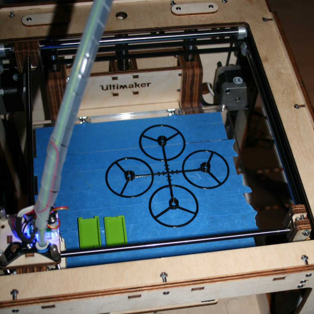
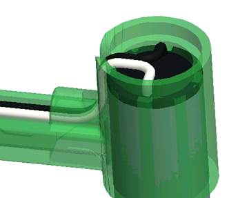
The mechanics – For the mechanics we have used freeCAD which is one of the few open-source 3D CADs tools that we have found. When we started out we had a lot of problems with this software because it keep crashing during the design. After the stable release of the 0.12 branch it’s gotten better but we’ve still had some problems with crashes. Over all we managed to design and 3D print many revision of the motors holder with freeCAD.
The website – On our server we are running WordPress, Mercurial and Redmine, all these on a Linux and Apache. We will probably also run phpBB later on.
Sensor poll
Waiting another week did not make things clearer whether to mount all sensors or not, but the quotation to buy and mount them did. The $20 we estimated was too low, depending on the amount of boards we make of course, but we would probably have to add another $10 to that which made the decision simple. It is mainly the barometer that is very expensive so we might still decide to mount the magnetometer. First we will do some tests though to find out how much “value” it really adds. For people that wants the barometer it will still be possible to manually mount it afterwards making it a win-win decision.


")


