Category: Software

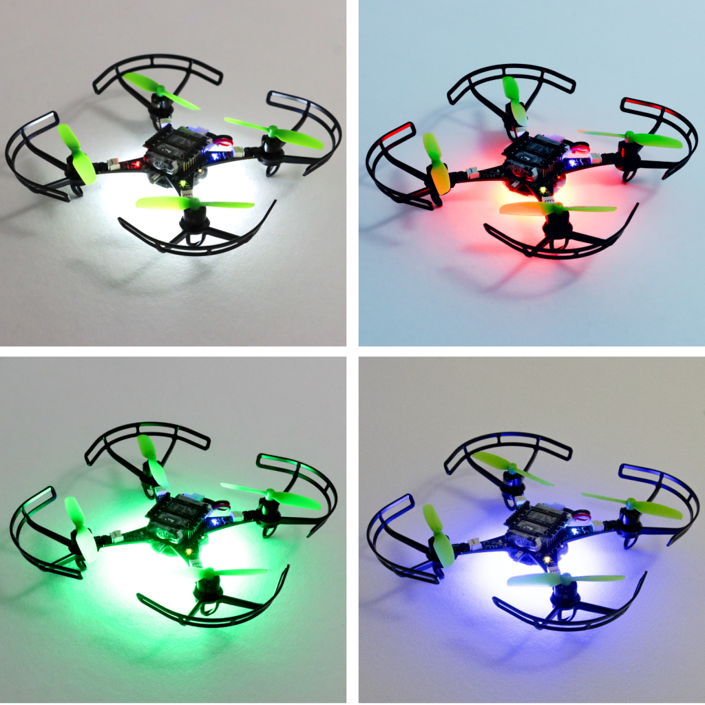
As 2024 comes to an end, it’s the perfect time to reflect on what we’ve accomplished over the past year. A major highlight has been our work on the Crazyflie 2.1 Brushless. We’re thrilled that it will be available early in the new year! While much of our efforts focused on refining and preparing the platform as a whole, we also introduced some standout features like support for contact charging on a charging pad, perfecting the specially optimized motors, and propeller guards to enhance safety for both users and the drone.

Finalizing the integration of the Crazyflie 2.1 Brushless into our software ecosystem and expanding its documentation were key steps in preparing for its launch. These efforts ensure compatibility, improve the user experience, and make the platform more accessible to the community. We’re looking forward to a smooth launch and to seeing how the community will utilize the new platform!

This year, we introduced updates to the Crazyflie 2.1 kit, making the 47-17 propellers the new default and including an improved battery. These upgrades enhance flight performance and endurance, culminating in the release of the Crazyflie 2.1+—an optimized iteration of our established platform.

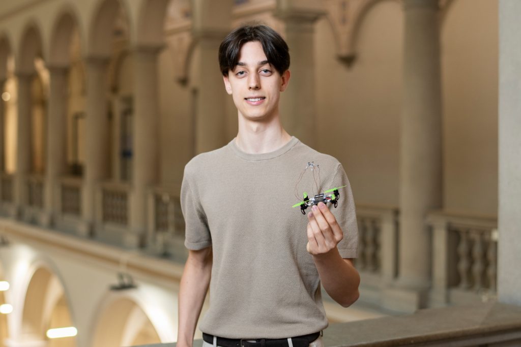
The Crazyflie 2.1 Brushless featured on the cover of Science Robotics vol. 9, no. 92

Community

In 2024, Bitcraze had an action-packed year, engaging with the robotics community through numerous conferences, workshops, and live events.

In May, we attended ICRA 2024 in Yokohama. We collected several research posters that now proudly feature at the office. Kimberly presented at the Robotics Developer Day, where she won Best Speaker Award for her impressive live hardware demos with ROS2. We co-organized the ‘Aerial Swarm Tools and Applications’ workshop at RSS 2024 in Delft. Arnaud and Kimberly shared insights on demo-driven development on an episode of OpenCV Live!. Additionally, we had a booth at ROSCon ’24 in Odense, connecting with the vibrant ROS community and showcasing our latest developments.

And don’t forget the developer meetings, where we shared some more behind the scenes information and collected invaluable feedback from the community.

We also released a new edition of our research compilation video, showcasing some of the coolest projects from 2023 and 2024 that highlight the versatility and impact of the Crazyflie platform in research.

Team

In the past year, Bitcraze saw significant changes within the team. in February, Rik rejoined the team. Tove started at Bitcraze in April. Mandy, with whom we’ve already worked extensively over the years, joined as our production representative in Shenzen. At the end of the year, we said goodbye to Kimberly, whose contributions will be deeply missed. Additionally, we had Björn with us for a few months, working on his master’s thesis on fault detection, and Joe continued his industrial postdoc at Bitcraze that began in December 2023. Looking ahead, Bitcraze is hiring for two new roles: a Technical Sales Lead and a Technical Success Engineer, to support our ongoing projects and customer collaborations.


As we close the chapter on 2024, we’re proud of the progress we’ve made, the connections we’ve strengthened, and the milestones we’ve reached. With exciting launches, new faces on the team, and continued collaboration with our community, we’re ready to soar to even greater heights in 2025. Thank you for being part of our journey!

We are excited to announce that we are working on several new link performance metrics for the Crazyflie that will simplify the troubleshooting of communication issues. Until now, users have had access to very limited information about communication links, relying primarily on a “link quality” statistic based on packet retries (when we have to re-send data) and an RSSI channel scan. Our nightly tests have been limited to basic bandwidth and latency testing. With this update, we aim to expose richer data that not only enables users to make more informed decisions regarding communication links but also enhances the effectiveness of our nightly testing process. In this blog post, we will explore the new metrics, the rationale behind their introduction, and how they will improve your interaction with the Crazyflie. Additionally, we will be holding a developer meeting on Wednesday November 13th to discuss these updates in more detail, and we encourage you to join us!

“Link Quality”—All or Nothing

Until now, users of the Crazyflie have had access to a single link quality metric. Implemented in the Python library, this metric is based on packet retries—instances when data packets need to be re-sent due to communication issues. This metric indicates that for every retry, the link quality drops by 10%, with a maximum of 3 retries allowed. As a result, the link quality score usually ranges from 70% to 100%, with a drop to 0% when communication is completely lost. However, as packet loss occurs, users often experience a steep decline, commonly seeing 100% when packets are successfully acknowledged or dropping to 0% when communication is completely lost.

Client representation of link quality; no link, yes link

The current link quality metric has served as a basic indicator but provides limited insight, often making it difficult to gauge communication reliability accurately. Recognizing these limitations, we’re introducing several new link performance metrics to the Crazyflie Python library, designed to provide a far more detailed and actionable view of communication performance.

What’s Coming in the Upcoming Update

The first metric we are adding is latency. We measure the full link latency, capturing the round-trip time through the library, to the Crazyflie, and back. This latency measurement is link-independent, meaning it applies to both radio and USB connections. The latency metric exposed to users will reflect the 95th percentile—a commonly used measure for capturing typical latency under normal conditions.

Next are several metrics that (currently) only support the radio link. For these, we distinguish between uplink (from the radio to the Crazyflie) and downlink (from the Crazyflie to the radio).

The first is packet rate, which simply measures the number of packets sent and received per second.

More interestingly, we are introducing a link congestion metric. Whenever there is no data to send, both the radio and the Crazyflie send “null” packets. By calculating the ratio of null packets to the total packets sent or received, we can estimate congestion. This is particularly useful for users who rely heavily on logging parameters or, for example, stream mocap positioning data to the Crazyflie.

The Received Signal Strength Indicator (RSSI) measures the quality of signal reception. Unlike our current “link quality” metric, we hope that a poor RSSI will serve as an early warning signal for potential communication loss. While RSSI tracking has been possible before with the channel scan example, this update will monitor RSSI in the library by default, and expose it to the user. The nRF firmware will also be updated to report RSSI by default. Currently, we only receive uplink RSSI, that is, RSSI measured on the Crazyflie side.

Work in progress client representation of new link performance metrics

We’ve already found these new metrics invaluable at Bitcraze. While we have, of course, measured various parameters throughout development, it was easy to lose track of the precise status of the communication stack. In the past, we relied more on general impressions of performance, but with these new metrics, we’ve gained a clearer picture. They’ve already shed light on areas like swarm latency, helping us fine-tune and understand performance far better than before.

You can follow progress on GitHub, and we invite you to try out these metrics for yourself. If there’s anything you feel is missing, or if you have feedback on what would make these tools even more helpful, we’d love to hear from you. Hit us up over on GitHub or join the developer meeting on Wednesday the 13th of November (see the join information on discussions).

We are happy to announce that release 2024.10 is now available! Special thanks to our community contributors for their valuable input and code contributions in this release!

Release overview

crazyflie-firmware release 2024.10 GitHub

crazyflie2-nrf-firmware release 2024.10 GitHub

crazyflie2-nrf-bootloader release 2024.10 GitHub

cfclient (crazyflie-clients-python) release 2024.10 GitHub, PyPI

cflib (crazyflie-lib-python) release 0.1.27 on GitHub, PyPI

User upgrade notice

While older versions may still function, users are encouraged to upgrade:

  • Minimum supported Python version changed to 3.10
  • Supported Ubuntu versions changed to 22.04 and 24.04

Major changes

  • Enhanced out-of-tree (OOT) kbuild configuration, allowing users to perform full Kconfig configuration for app layer applications.
  • Introduced recovery functionality, allowing users or scripts to safely re-enable the system after a crash without reboot.
  • Added a timeout for auto-disarming, allowing the system to remain armed during brief landings in manual arming mode.
  • Introduced a workaround for PID derivative kick, improving the performance of the PID controller during large setpoint changes (#1337, #1403).
  • Spiral and constant velocity high-level commander segments (#1410).
  • Changed BLE name format to include part of the NRF MAC address, allowing users to easily differentiate between Crazyflies.

For detailed release notes, check out the individual releases on GitHub. Links can be found in the release overview above.

As you might expect, we use the Crazyflie python client a lot at Bitcraze. The client has a lot of features, ranging from setting up LPS/Lighthouse systems to turning on/off the headlight LEDs on the LED-ring deck. But some of the features we use the most is probably the console view as well as the logging/parameter subsystems. A lot of the time we modify firmware, flash it and want to tweak (via parameters) or to check if the changes are working as expected (via the console or logging). Then switching from the terminal, where we build/flash, to the Qt UI in the Crazyflie python client can be a hassle if you just want to do something quick. It would be great to be able to log/set variables directly from the terminal, well now you can!

Meet the Crazyflie command-line client, a fun Friday project I worked on a while back. The CLI is written in Rust and was made possible thanks to a previous fun Friday project by Arnaud on the Rust Crazyflie link/lib, which has now moved to the official Bitcraze repositories. The CLI project is still very limited, but has some basic functionality:

  • Scan for Crazyflies and pre-select one to interact with
  • List loggable variables, create log configurations and print their value
  • List parameters and get/set them
  • Show the Crazyflie console

Last week the first version, v0.1.0, was released on crates.io. So if you have Rust set up on your computer and want to test it out then all you need to do is to type “cargo install cfcli“. The CLI still only has some basic functionality, but hopefully it can be expanded in the future with more useful things! Feel free to leave any issues or comments you might have on the Github page.

You might remember that at the beginning of this summer, we were invited to do a skill-learning session with the Crazyflie at the Robotics Developer Day 2024 (see this blog post) organized by The Construct. We showed the Crazyflie flying with the multi-ranger deck, capable of mapping the room in both simulation and the real world. Moreover, we demonstrated this with both manual control and autonomous wall-following. Since then, we wanted to make some improvements to the simulation. We now present an updated tutorial on how to do all of this yourself on your own machine.

This tutorial will focus on using the multi-ranger ROS 2 nodes for both mapping and wall-following in simulation first, before trying it out on the real thing. You will be able to tune settings to your specific environment in simulation first and then use exactly the same nodes in the real world. That is one of the main strengths of ROS, providing you with that flexibility.

We have made a video of what to expect of the tutorial, for which you should use this blogpost for the more detailed instructions.

Watch this video first and then again with the instructions below

What do you need first?

You’ll need to setup some things first on the PC and acquire hardware to follow this tutorial in full:

PC preparation

You’ll need to install ROS 2 and Gazebo simulator maintained by the Open Robotics foundation on an Ubuntu machine.

  • Ubuntu 22.04 on a 64-bit x86 device (no ARM)
  • ROS 2 Humble – Install it via these instructions
  • Gazebo Harmonic – Install via these instructions This is not the recommended Gazebo for humble but we will install the specific ROS bridge for this later. Just make sure that you don’t have gazebo classic installed on your machine.

Hardware

You’ll need to components at least of the STEM ranging bundle

If you have any different setup of your computer or positioning system, it is okay as the demos should be simple enough to work, but, be prepared for some warning/error handling that this tutorial might have not covered.

Time to complete:

This is an approximation of how much time you need to complete this tutorial, depended on your skill level, but if you already have experience with both ROS 2/Gazebo and the Crazyflie it should take 1 hour.

If you have the Crazyflie for the first time, it would probably be a good idea to go through the getting started tutorial and connect to it with a CFclient with the Flowdeck and Multi-ranger deck attached as a sanity check if everything is working before jumping into ROS 2 and Gazebo.

Some things holds for ROS 2! It would be handy to go through the ROS 2 Humble beginner tutorials before starting.

1. Installation

This section will install 4 packages:

Make the workspaces for both simulation and ROS. You can use a different directory for this

mkdir ~/crazyflie_mapping_demo
cd crazyflie_mapping_demo
mkdir simulation_ws
mkdir ros2_ws
cd ros2_ws
mkdir src

Let’s clone the repositories in their right location, starting with simulation

cd ~/crazyflie_mapping_demo/simulation_ws
git clone https://github.com/bitcraze/crazyflie-simulation.gitCode language: JavaScript (javascript)

Then navigate to the ROS2 workspace source folder and clone 3 projects:

cd ~/crazyflie_mapping_demo/ros2_ws/src
git clone https://github.com/knmcguire/crazyflie_ros2_multiranger.git
git clone https://github.com/knmcguire/ros_gz_crazyflie
git clone https://github.com/IMRCLab/crazyswarm2 --recursiveCode language: PHP (php)

First install certain requirements as apt-get packages and pip libraries (might want to make a python environment for the latter)

sudo apt-get install libboost-program-options-dev libusb-1.0-0-dev python3-colcon-common-extensions
sudo apt-get install ros-humble-motion-capture-tracking ros-humble-tf-transformations
sudo apt-get install ros-humble-ros-gzharmonic ros-humble-teleop-twist-keyboard
pip3 install cflib transform3D Code language: JavaScript (javascript)

Also follow the instructions to give the proper rights to the Crazyradio 2.0 in this guide, but if this is your first time of working with the Crazyradio 2.0 first follow this tutorial.

Go to the ros2_ws workspace and build the packages

cd  ~/crazyflie_mapping_demo/ros2_ws/
source /opt/ros/humble/setup.bash
colcon build --cmake-args -DBUILD_TESTING=ONCode language: JavaScript (javascript)

Building will take a few minutes. Especially Crazyswarm2 will show a lot of warnings and std_err, but unless the package build has ‘failed’, just ignore it for now until we have proposed a fix to that repository.

If the build of all the packages passes and non failed, please continue to the next step!

2. Simple mapping simulation

This section will explain how to create a simple 2D map of your environment using the multi-ranger. The ROS 2 package designed for this is specifically made for the multi-ranger, but it should be compatible with NAV2 if you’d like. However, for now, we’ll focus on a simple version without any localization inferred from the map.

Open up a terminal which needs to be sourced for both the gazebo model and the newly build ROS 2 packages:

source ~/crazyflie_mapping_demo/ros2_ws/install/setup.bash
export GZ_SIM_RESOURCE_PATH="/home/$USER/crazyflie_mapping_demo/simulation_ws/crazyflie-simulation/simulator_files/gazebo/"Code language: JavaScript (javascript)

First lets be safe and start with simulation. Startup the ROS 2 launch files with:

ros2 launch crazyflie_ros2_multiranger_bringup simple_mapper_simulation.launch.pyCode language: CSS (css)

If you get a ‘No such file or directory’ error on the model, try entering the full path in GZ_SIM_RESOURCE_PATH export.

Gazebo will start with the Crazyflie in the center. You can get a close-up of the Crazyflie by right-clicking it in the Entity tree and pressing ‘Move to’. You can also choose to follow it, but the camera tracking feature of Gazebo needs some tuning to track something as small as the Crazyflie. Additionally, you will see RVIZ starting with the map view and transforms preconfigured.

Open up another terminal, source the installed ROS 2 distro and open up the ROS 2 teleop keyboard node:

source /opt/ros/humble/setup.bash
ros2 run teleop_twist_keyboard teleop_twist_keyboard

Have the Crazyflie take off with ‘t’ on your keyboard, and rotate it around with the teleop instructions. In RVIZ you should see the map being created and the transform of the Crazyflie moving. You should be able to see this picture, and in this part of the video.

Screenshot of the Crazyflie in Gazebo generating a map with Teleop (video)

3. Simple mapping real world

Now that you got the gist of it, let’s move to the real Crazyflie!

First, if you have a different URI of the Crazyflie to connect to, first change the config file ‘crazyflie_real_crazyswarm2.yaml’ in the crazyflie_ros2_repository. This is a file that Crazyswarm2 uses to know to which Crazyflie to connect to.

Open up the config file in gedit or your favorite IDE like visual code:

gedit ~/crazyflie_mapping_demo/ros2_ws/src/crazyflie_ros2_multiranger/crazyflie_ros2_multiranger_bringup/config/crazyflie_real_crazyswarm2.yamlCode language: JavaScript (javascript)

and change the URI on this line specifically to the URI of your Crazyflie if necessary. Mind that you need to rebuild ros2_ws again to make sure that this has an effect.

Now source the terminal with the installed ROS 2 packages and the Gazebo model, and launch the ROS launch of the simple mapper example for the real world Crazyflie.

source ~/crazyflie_mapping_demo/ros2_ws/install/setup.bash
export GZ_SIM_RESOURCE_PATH="/home/$USER/crazyflie_mapping_demo/simulation_ws/crazyflie-simulation/simulator_files/gazebo/"
ros2 launch crazyflie_ros2_multiranger_bringup simple_mapper_real.launch.py
Code language: JavaScript (javascript)

Now open up another terminal, source ROS 2 and open up teleop:

source /opt/ros/humble/setup.bash
ros2 run teleop_twist_keyboard teleop_twist_keyboard

Same thing, have the Crazyflie take off with ‘t’, and control it with the instructions.

You should be able to see this on your screen, which you can also check with this part of the video.

Screen shot of the real Crazyflie mapping while being controlled with ROS 2 teleop (video)

Make the Crazyflie land again with ‘b’, and now you can close the ROS 2 node in the launch terminal with ctrl + c.

4. Wall following simulation

Previously, you needed to control the Crazyflie yourself to create the map, but what if you could let the Crazyflie do it on its own? The `crazyflie_ros2_multiranger` package includes a `crazyflie_ros2_multiranger_wall_following` node that uses laser ranges from the multi-ranger to perform autonomous wall-following. Then, you can just sit back and relax while the map is created for you!

Let’s first try it in simulation, so open up a terminal and source it if you haven’t already (see section of the Simple mapper simulation). Then launch the wall follower ROS 2 launch file:

ros2 launch crazyflie_ros2_multiranger_bringup wall_follower_mapper_simulation.launch.pyCode language: CSS (css)

Take off and wall following will go fully automatic. The simulated Crazyflie in Gazebo will fly forward, stop when it sees a wall with it’s forward range sensor and follow the wall on its left-hand side.

You’ll see on RVIZ2 when the full map is created like here below and this part of the tutorial video.

Screenshot of the simulated Crazyflie in Gazebo mapping will autonomously wall following (video)

You can stop the simulated Crazyflie by the following service call in another terminal that is sourced with ROS 2 humble.

ros2 service call /crazyflie/stop_wall_following std_srvs/srv/Trigger

The simulated Crazyflie will stop wall following and land. You can also just close the simulation, since nothing can happen here.

5. Wall following real world

Now that we have demonstrated that the wall-following works in simulation, we feel confident enough to try it in the real world this time! Make sure you have a fully charged battery, place the Crazyflie on the floor facing the direction you’d like the positive x-axis to be (which is also where it will fly first), and turn it on.

Make sure that you are flying with a room with clear defined walls and corners, or make something with cardboard such as a mini maze, but the current algorithm is optimized to just fly in a squarish room.

Source the ROS 2 workspace like previously and start up the wall follower launch file for the

ros2 launch crazyflie_ros2_multiranger_bringup wall_follower_mapper_real.launch.pyCode language: CSS (css)

Like the simulated Crazyflie, the real Crazyflie will take off automatically and automatically do wall following, so it is important that it is flying towards a wall. It should look like this screenshot, or you can check it with this part of the video.

The real crazyflie wall following autonomously while mapping the room (video).

Be careful here to not accidently run this script with the Crazyflie sitting on your desk!

If you’d like the Crazyflie to stop, don’t stop the ROS2 nodes with ctrl-c, since it will continue flying until crash. It’s not like simulation unfortunately where you can close the environment and nothing will happen. Instead, use the ROS 2 service made for this in a different terminal:

ros2 service call /crazyflie_real/stop_wall_following std_srvs/srv/Trigger

Similar the real Crazyflie will stop wall following and land. Now you can close the ROS 2 terminals and turn off the crazyflie.

Next steps?

We don’t have any more demos to show but we can give you a list of suggestions of what you could try next! You could for instance have multiple Crazyflies mapping together like in the video shown here:

This uses the mapMergeForMultiRobotMapping-ROS2 external project, which is combined with Crazyswarm2 with this launch file gist. Just keep in mind that, currently, it would be better to use a global positioning system here, such as the Lighthouse positioning system used in the video. Also, if you’d like to try this out in simulation, you’ll need to ensure different namespaces for the Crazyflies, which the current simulation setup may not fully support.

Another idea is to connect the NAV2 stack instead of the simple mapper. There exists a couple of instructions on the Crazyswarm2 ROS2 tutorials so you can use those as reference. Check out the video below here.

Moreover, if you are having difficulties setting up your computer, I’d like to remind you that the skill-learning session we conducted for Robotics Developer Day was entirely done using a ROSject provided by The Construct, which also allows direct connection with the Crazyflie. The only requirement is that you can run Crazyswarm2 on your local machine, but that should be feasible. See the video of the original Robotics Developer Day skill-learning session here:

The last thing to know is that the ROS 2 nodes in this tutorial are running ‘offboard,’ so not on the Crazyflies themselves. However, do check out the Micro-ROS examples for the Crazyflie by Eprosima whenever you have the time and would like to challenge yourself with embedded development.

That’s it, folks! If you are running into any issues with this tutorial or want to bounce some cool ideas to try yourself, start a discussion thread on https://discussions.bitcraze.io/.

Happy hacking!

We are excited to announce the release of our new PID Tuning Guide! This guide is designed to help users understand and apply the basics of PID tuning within our ecosystem, making it easier to achieve stable and responsive flight for your Crazyflie. This guide is particularly useful if you’ve modified your drone, such as adding expansion decks or changing its motor and/or propeller configuration. While our default tuning is designed to work in a wide range of situations and configurations, fine-tuning your PID settings can enhance performance for your specific setup and flight profile.

Interface with tuning toolbox and plotter displaying the roll angle setpoint and the roll angle state estimate.

What’s in the guide?

The guide covers essential topics, including:

  • Fundamental PID Concepts: Understand the role of Proportional, Integral, and Derivative parameters in controlling your Crazyflie’s movements.
  • Step-by-Step Instructions: Learn how to set up your software, and use cfclient for tuning.
  • Practical Tuning Tips: Get insights on adjusting PID gains, using the tuning toolbox, and conducting safe manual flight tests.

Why this guide is useful

Even though this guide focuses on the basics, it provides a solid foundation for anyone new to PID tuning. Whether you’re using the Crazyflie 2.1, Crazyflie 2.0, or a custom-built quadcopter with the Crazyflie Bolt, this guide will help you:

  • Understand how PID controllers work and why they are important.
  • Use the cfclient for PID tuning within our ecosystem.

Safety first

We prioritize safety in our guide. Always secure your quadcopter in a safe environment, use protective gear, and configure an emergency stop on your controller to ensure a safe tuning process.

Get started with PID tuning today!

Ready to improve your quadcopter’s flight performance? Check out our PID Tuning Guide and start tuning.

This week, we have a guest blog post from Scott at Droneblocks.

DroneBlocks is a cutting-edge platform that has transformed how educators worldwide enrich STEM programming in their classrooms. As pioneers in the EdTech space, DroneBlocks wrote the playbook on integrating drone technology into STEM curriculum for elementary, middle, and high schools, offering unparalleled resources for teaching everything from computer science to creative arts. What started as free block coding software and video tutorials has become a comprehensive suite of drone and robotics educational solutions. The Block-Coding software still remains free to all, as the DroneBlocks mission has always been to empower educators and students, allowing them to explore and lead the way. This open-source attitude set DroneBlocks on a mission to find the world’s best and most accessible micro-drone for education, and they found it in Sweden!

Previously, DroneBlocks had worked alongside drone juggernaut DJI and their Tello Drone. The Tello was a great tool for its time, but when DJI decided to discontinue it with little input from its partners and users, it made the break much easier. The hunt began for a DJI Tello replacement and an upgrade!

Bitcraze’s choice to build Crazyflie as an open platform had their drone buzzing wherever there was curiosity. The Crazyflie was developed to fly indoors, swarm, and be mechanically simplistic. DroneBlocks established that the ideal classroom micro-drone required similar characteristics. This micro-drone needed to be small for safety but sturdy for durability. It also needed to be easy to assemble and simple in structure for students new to drones. Most importantly, the ideal drone needed to have an open line of software communication to be fully programmable. Finally, there had to be an opportunity for a long-lasting partnership with the drone manufacturer, including government compliance.

After extensive searching and testing by DroneBlocks, the Crazyflie was a diamond in the rough – bite-sized and lightweight, supremely agile and accurate, reliable and robust, and most importantly, it was an open-source development platform. The DroneBlocks development team took the Crazyflie for a spin (or several) and with excitement, it was shared with the larger curriculum team to be mined for learning potential. It was promising to see Crazyflie’s involvement in university-level research studies, which proved it meant business. DroneBlocks knew the Crazyflie had a lot going for it – on its own. The team imagined how, when paired with DroneBlocks’ Block Coding software, Flight Simulator, and Curriculum Specialists, the Crazyflie could soar to atmospheric heights! 

Hardware? Check. Software? Check. But what about compatibility? DroneBlocks was immediately drawn to the open communication and ease of conversation with the Bitcraze team. It was obvious that both Bitcraze and DroneBlocks were born from a common thread and shared a mutual goal: to empower people to explore, investigate, innovate, research, and educate. 

DroneBlocks has since built a new Block Coding interface around the Crazyflie, allowing students to pilot their new drone autonomously and learn the basics of piloting and coding concepts. This interface is offered with a brand new drone coding simulator environment so students can test their code and fly the Crazyflie in a virtual classroom environment.

The Crazyflie curriculum currently consists of courses covering building, configuring, and finally, programming your drone with block coding (DroneBlocks) and Python. DroneBlocks’ expert curriculum team designed these courses to enable learners of all ages and levels to learn step by step through video series and exercises. New courses around block coding and Python are in constant development and will be continuously added to the DroneBlocks curriculum platform.

Crazyflie Drones now headline DroneBlocks’ premiere classroom launch kit. The DroneBlocks Autonomous Drones Level II kit encompasses everything a middle or high school would need to launch a STEM drone program, including the hardware, necessary accessories, and safety wear paired with the DroneBlocks software and curriculum. As a result, thousands of new students have entered the world of Drones and programming thanks to the Bitcraze + DroneBlocks partnership.

DroneBlocks has become an all-inclusive drone education partner for engaging and innovative learning experiences—and the Crazyflie delivers this by being a cutting-edge piece of hardware in a clever package.

Welcome to the “The Beginner’s Guide to Drones” for programmers curious about exploring the world of unmanned aerial vehicles (UAVs). If you’re a coder from another field, this guide will walk you through the basics of drones, their components, and how to start programming them. Let’s dive in and see how your coding skills can take flight!

If you come from an engineering field, you might already know the basics of some of these topics, however you might still have use of the overview and can use the resources to get more specific knowledge.

The Robotics part

First and foremost, you’ll need some basic robotics skills.
We start of with the most basic question, “What is a Robot?”. A robot uses sensors to create an internal model of its environment, and actuators to act on/in its environment. The specifics of the internal model depend on the robot’s purpose, but a crucial component is understanding its location and orientation within that environment.

Linear algebra basics

To understand how a quadcopter perceives its environment and its own position, you’ll need some basic skills in linear algebra, particularly in matrices, vectors, and frame rotation. These skills are essential for comprehending the mathematical principles behind quadcopter navigation.

To build an internal model of its own movement and orientation, an Inertial Measurement Unit (IMU) is used. An IMU consists of a gyroscope, an accelerometer, and sometimes a magnetometer. These sensors, when combined using sensor fusion techniques (See “Control Theroy” below), help determine the quadcopter’s angular velocity and linear acceleration. This data allows the drone to calculate its orientation and movement.

Picture of a Crazyflie in relation to a reference frame from Bitcraze.io

For a detailed understanding of these processes, please refer to the following resources:
Visual description of frame transformations;
https://www.youtube.com/watch?v=kYB8IZa5AuE
Basic coordinate transformations;
https://motion.cs.illinois.edu/RoboticSystems/CoordinateTransformations.htmlbasi

Positioning techniques

The quadcopter can now determine its relationship to its starting position and the gravitational field. However, relying solely on an IMU tends to cause drift over time. Imagine trying to stand on one leg with your eyes closed—eventually, you’ll lose balance.

For improved stability, a drone often needs additional sensors, such as a camera, to help stabilize its position. Other sensor systems can also be used to determine relative or absolute position. While an IMU can sense changes in position relative to a starting point, an external positioning system is necessary for stability and obtaining absolute positions. This system acts as a reference frame for the drone.

Drones flying outdoors typically use GPS combined with RTCM, since it is available almost anywhere, ease to use, and has centimeter-level accuracy.

For indoor use, as with Crazyflies, the default used positioning system is motion-capture system but there are others as well. This area is at the cutting edge of science, with new technologies emerging constantly. However, many effective systems are available, though they may have constraints regarding power efficiency, flight area size, update speed, or precision.

This is an image of some common techniques for positioning. a) AOA, b) TOA, TWR c) TDOA taken from Researchgate.com

Control theory

Now that drone can understand its position and orientation in space, the next step is figuring out how to move within this space. Moving from point A to point B involves setting a “setpoint” and then determining how to use the drone’s actuators to reach this setpoint most efficiently. This is where control theory comes into play.

Drones generally use some sort of feedback control system, which in its most basic form looks something like this:

A very basic overview of a system with feedback control

In this system, the error (the difference between the current position and the setpoint) is fed back into the system to ensure the drone moves in a way that minimizes the error over time.

Various algorithms can calculate the best actuator output based on the error and current state. One of the most fundamental algorithms is the PID controller, which works well for linear systems. Understanding PID controllers requires some basic calculus, but the concept is straightforward. Here are some resources for simple explanations:

For IMUs, there is a particularly useful filter to know about, given its widespread use. The accelerometer and gyroscope each have their own profiles of noise and drift. The accelerometer is sensitive to short-term noise, while the gyroscope drifts slowly over time. To mitigate these issues, a combination of both measurements is often used. The complementary filter is ideal for this situation, leveraging the strengths of both sensors to correct the measurements effectively.

More information on how to use the complementary filter for IMUs can be found here:
https://www.hackster.io/hibit/complementary-filter-and-relative-orientation-with-mpu9250-d4f79d

For more complex scenarios, advanced controllers like Kalman filters and others can be used. It’s also possible to combine multiple controllers to achieve better performance.

Basic overview of feedback control systems;
https://control.com/textbook/closed-loop-control/basic-feedback-control-principles/

The flying part

Now lets get into the exciting part. FLYING!!!

Actuators

Drone actuators, primarily consisting of motors and propellers, are critical for controlling a drone’s movement and stability. The motors and propellers are typically called the “drive train” or “power train”.
The motors used on drones are usually brushed or brushless DC motors. Propellers are attached to the motors and generate lift by pushing air downwards. The size, shape, and pitch of the propellers affect the drone’s performance, including speed, lift, and maneuverability. Together, the precise control of motors and propellers enables a drone to perform complex maneuvers, maintain stability, and achieve efficient flight.

Pictures of forces acting on a drone in flight


This is an almost all you need guide to get an overview of drone flight dynamics
https://dronstechnology.com/the-physics-of-drone-flight-lift-thrust-drag-and-weight/

Stock information

As of now the Crazyflie 2.1 is out of stock, unfortunately. They’re expected back in stock around August 20th – 4 weeks from now. You can sign up in our shop to be notified as soon as they arrive!
https://store.bitcraze.io/collections/kits/products/crazyflie-2-1?variant=19575412719703

We are happy to announce the latest updates to the Crazyflie client and Python library. Major changes include improved persistent parameter management, enhanced plotting with new x-axis manipulation features, and new default logging configurations (for PID tuning). Minor updates include bug fixes and documentation improvements.

Updated plotter tab. Besides the existing option for a number of samples, users can now set x-axis limits to a number of seconds or a time range.
Updated parameters tab. Users can now mass dump/load persistent parameters to/from a file, or clear all stored persistent parameters.

For detailed release notes, check out crazyflie-lib-python release 0.1.26 and crazyflie-clients-python release 2024.7.

This week we have a guest blogpost by Christian Llanes, a Robotics PhD of from Formal Methods & Autonomous Control of Transportation Systems Lab of the Georgia Institute of Technology. Enjoy!

Why do we need simulators?

Simulators are one of the most important tools used in robotics research. They usually are designed for different purposes with different levels of complexity. For example, simulators with low computational overhead that are parallelizable are mainly used for either training reinforcement learning algorithms or Monte Carlo sampling for verification of task completion in a nondeterministic environment. Some simulators also use rendering engines for the graphical display of models and the environment or when cameras are intended to be used in the robotics platform. Simulation is also useful for the development and deployment of new robotics firmware features where the firmware is compiled on a test machine and run in the loop with a simulated sensor suite. This simulator configuration is known as software-in-the-loop (SITL) because the vehicle firmware is intended to be run in the loop with the simulated vehicle physics and/or rendering engine. This feature is supported by autopilot suites such as PX4ArduPilotCogniPilot, and BetaFlight. This feature is not officially supported yet for Crazyflies because it requires a large overhaul of the firmware to be able to compile on a desktop machine and interact with different simulators such as Gazebo, Webots, PyBullet, CoppeliaSim, Isaac Sim, or Unreal Engine.

CrazySim

Last summer I began working with Crazyflies and noticed this Crazyflie simulator gap. I stumbled on a community-developed project for Crazyflie SITL called sim_cf. This project is exactly what I was looking for. However, the firmware used by the project is from July 2019 and the official firmware has had over 2000 commits made since then. The project also uses ROS 1, Gazebo Classic, and doesn’t support the Crazyflie Python library (CFLib). Using this project as a starting point I set out to develop CrazySim–a Crazyflie SITL project that doesn’t require ROS, uses Gazebo Sim, and supports connectivity through CFLib. Using CFLib we can connect the simulator to external software such as Crazyswarm2 or the Crazyflie ground station client. Users test their control algorithms in the external software using the simulator interface before deploying to real flight hardware.

An example of offboard model predictive control design and deployment workflow using CrazySim.

Using the Crazyflie Client for PID Tuning

We have also provided a modified Crazyflie client for CrazySim support. The Crazyflie client is a cool tool for testing a single drone in hardware. We can perform command based flight control, look at real time plots, save log data, and tune PID values in real time. The PID values are typically tuned for an out of the box Crazyflie. However, when we modify the Crazyflie and add extra weight through batteries, decks, and upgraded thrust motors then the behavior of the Crazyflie will change. If a user wants to tune a custom Crazyflie setup, then they can add additional models in this folder with their own motor and mass properties. Then they just need to add it to the list of supported models in either of the launch scripts. There is already an example model for the thrust upgrade bundle. Documentation for installing the custom client can be found here.

PID tuning a simulated Crazyflie using CrazySim on the Crazyflie PC client.

Crazyswarm2

We can now connect to the simulated Crazyflie firmware using CFLib. Therefore, we can set up a ROS 2 interface through Crazyswarm2 for swarm command and control through ROS 2 topics and services. To do this we first startup the drones using any of the launch scripts.

bash tools/crazyflie-simulation/simulator_files/gazebo/launch/sitl_multiagent_square.sh -n 16 -m crazyflie

Then, we bring up Crazyswarm2 after setting up the configuration file for the number of drones chosen.

ros2 launch crazyflie launch.py backend:=cflib

We demonstrate an example of how we can control a swarm of drones using Crazyswarm2 GoTo service commands.

Crazyswarm2 GoTo service commands using CrazySim.

ICRA 2024

CrazySim is also being presented as a paper at the 2024 IEEE International Conference on Robotics and Automation in Yokohama, Japan. If you are attending this conference and are interested in this work, then I invite you to my presentation and let me know that you are coming from this blog post after. For the paper, I created a multi agent decentralized model predictive controller (MPC) case study on ROS 2 to demonstrate the CrazySim simulation to hardware deployment workflow. Simulating larger swarms with MPC may require a high performance computer. The simulations in this work were performed on an AMD Ryzen 9 5950X desktop processor.

Model predictive control case study for ICRA 2024 paper.

Links

  1. CrazySim
  2. Modified Crazyflie client

Other Crazyflie SITL projects:

  1. sim_cf
  2. sim_cf2 blog post
  3. LambdaFlight blog post