Category: Software

For the last four years of doing my PhD at the TU Delft and the MAVlab, we were determined to figure out how to make a swarm/group of tiny quadcopters fly through and explore an unknown indoor environment. This was not easy, as many of the sub-challenges that needed to be solved first. However, we are happy to say that we were able to show a proof-of-concept in the latest Science Robotics issue! Here you can see the press release from the TU Delft for general information about the project.

Since we used the Crazyflie 2.0 to achieve this result, this blog-post we wanted to mostly highlight the technical side of the research, of the achievements and the challenges we had to face. Moreover, we will also explain the updated code which uses the new features of the Crazyflie Firmware as explained in the previous blogpost.

A swarm of drones exploring the environment, avoiding obstacles and each other. (Guus Schoonewille, TU Delft)

Hardware

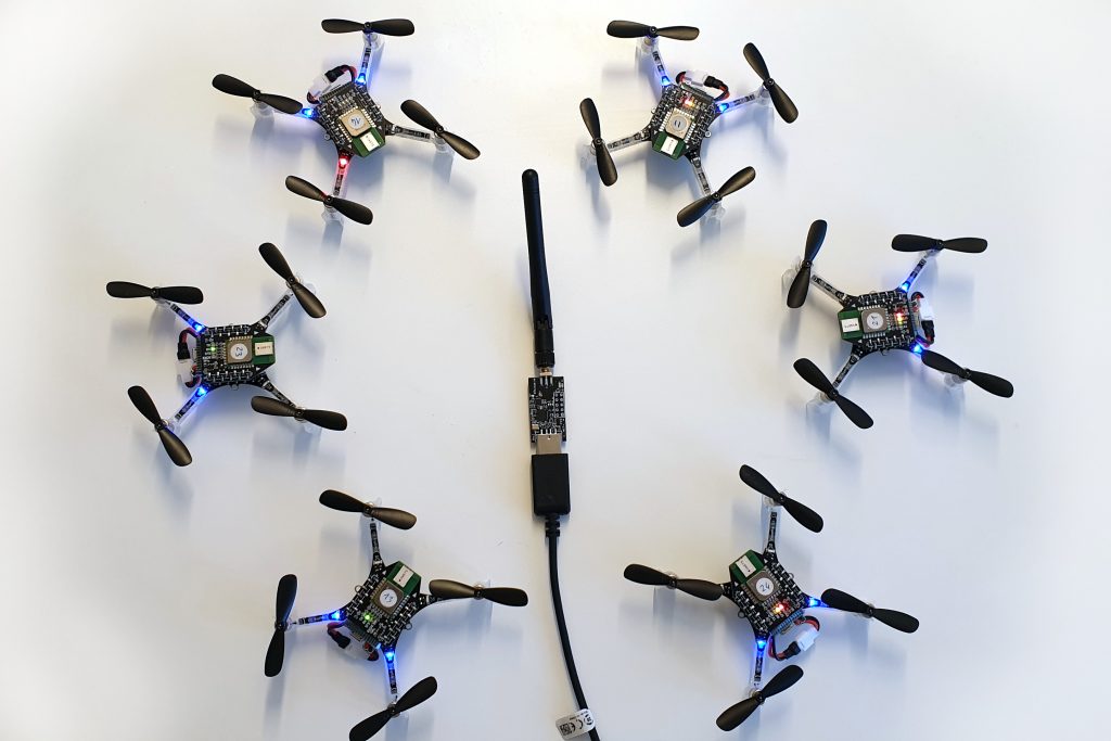
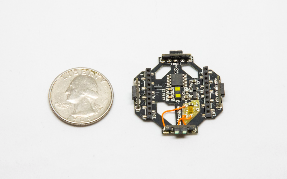
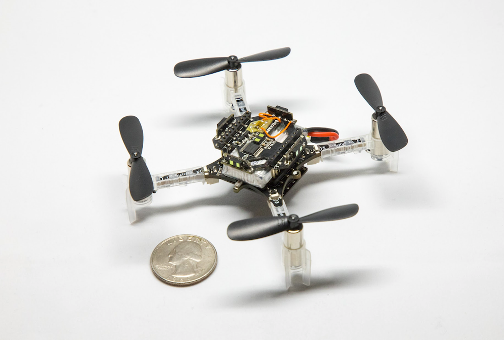
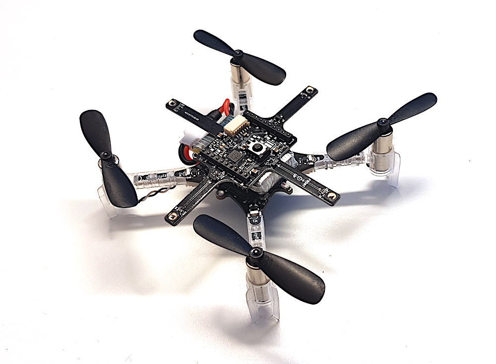
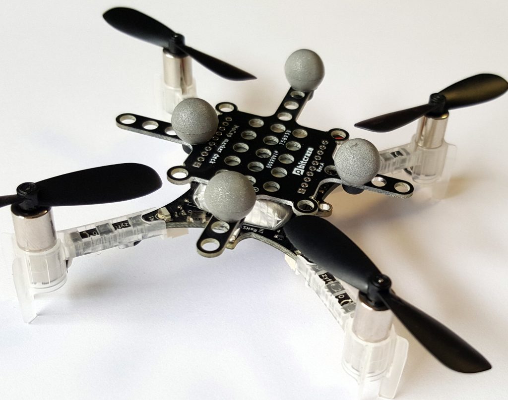
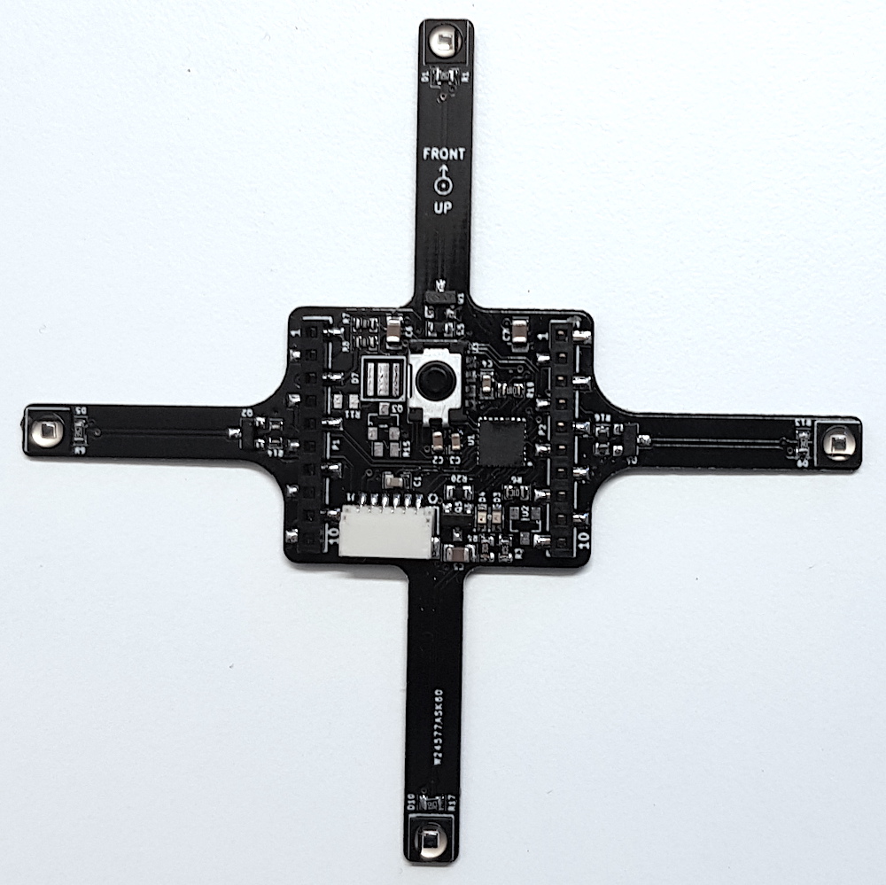
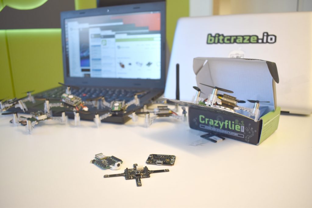
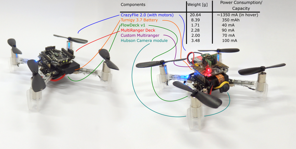
In the paper, we presented a technique called Swarm Gradient Bug Algorithm (SGBA), which borrows (as the name suggests) navigational elements from the path planning technique called ‘Bug Algorithms’ (see this paper for an overview). The basic principle is that SGBA is a state-machine with several simple behavior presets such as ‘going to the goal’, ‘wall-following’ and ‘avoiding other Crazyflies’. Here in the bottom you can see all the modules were used. For the main experiments (on the left), the Crazyflie 2.0’s were equipped with the Multiranger and the Flowdeck (here we used the Flow deck v1). On the right you see the Crazyflies used for the application experiment, were we made an custom Multiranger deck (with four VL53L0x‘s) and a Hubsan Camera module. For both we used the Turnigy nanotech 300 mAh (1S 45-90C) LiPo battery, to increase the flight time to 7.5 min.

Hardware used in the experiments. Adapted from the science robotics paper.

Experiments

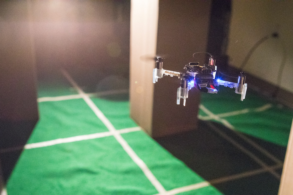
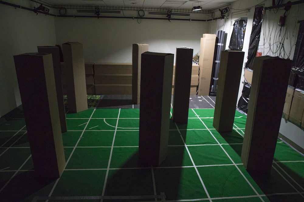
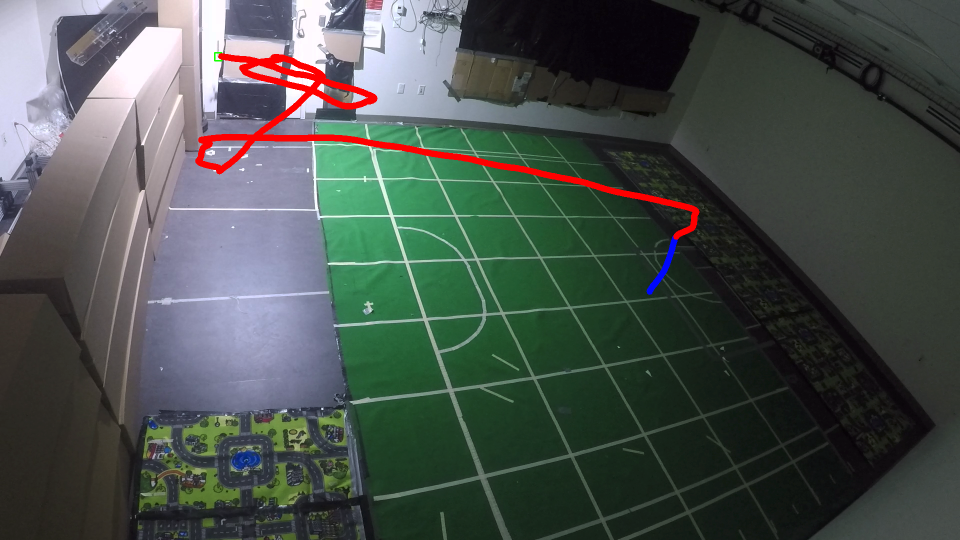
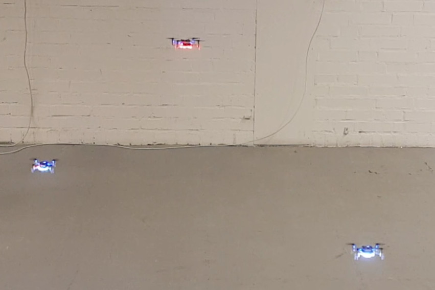
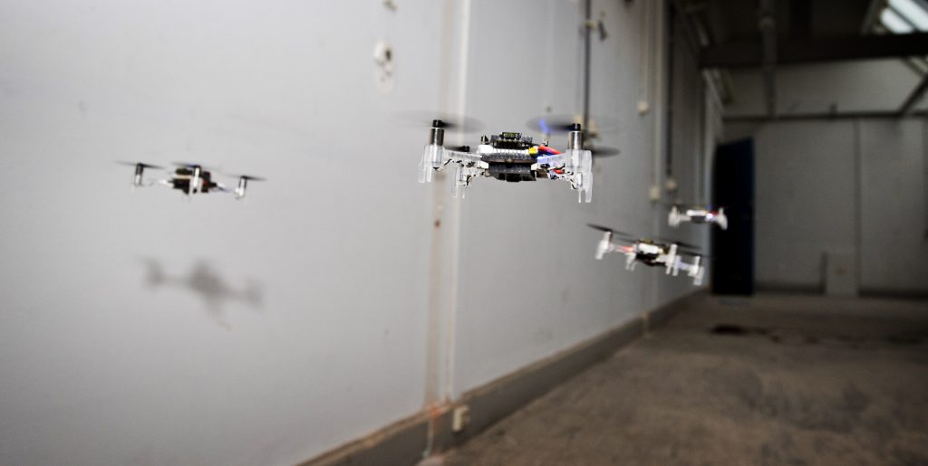
With this, we were able to have 6 Crazyflies explore an empty office floor in the faculty building of Aerospace engineering. They started out in the middle of the test environment and flew all in different preferred directions which they upheld by their internal estimated yaw angle. With the multi-rangers, they managed to detect walls in their, and followed its border until the way was clear again to follow their preferred direction. Based on their local odometry measurements with the flowdeck, the Crazyflies detected if they were flying in a loop, in order to get out of rooms or other situations.

A little before half way of their battery life, they would try to get back to their initial position, which they did by measuring the Received Signal Strength Intensity of the Crazyradio PA home beacon, which was located at their initial starting position. During wall-following, they measured the gradient of the RSSI, to determine in which directions it increases or decreases, to estimate the angle back the goal.

While they were navigating, they were also communicating with each-other by means of broadcasting messages. Based on those measurements of RSSI, they could sense other Crazyflies approaching, which they first of all used for collision avoidance (by letting the low priority CFs move out of the way of the high priority CFs). Second of all, during the initial exploration phase, they communicated their preferred direction as well, so that one of them can change its exploration behavior to not conflict with the other. This way, we tried to maximize the explored area by the Crazyflies.

One of those experiments with 6 Crazyflies can be seen in this video for better understanding:

We also showed an application experiment where 4 crazyflies with the camera modules searched for 2 dummies in the same environment.

Challenges

In order to get the results presented above, there were many challenges to overcome during the development phase. Here is a list that explains a couple of the elements that needed to work flawlessly:

  • Single CF robustness: We used the Flowdeck v1, for the ‘deadlock’ detection and the basic velocity control, which was challenging in the testing environment because of low lighting conditions and texture. Therefore the Crazyflies were flying at 0.5 meters in order to ensure robustness. The wall-following was performed solely using the Multiranger. This was tested out in many situations and was able to handle a lot of type of obstacles without any problem. However the limited FOV of the laser range finder can not detect all types of obstacles, for instance thin ones or irregular ones such as plants. Luckily these were not encountered in the environment the Crazyflies flew in, but to increase robustness, we will need to consider adding a camera to the navigational drive as well.
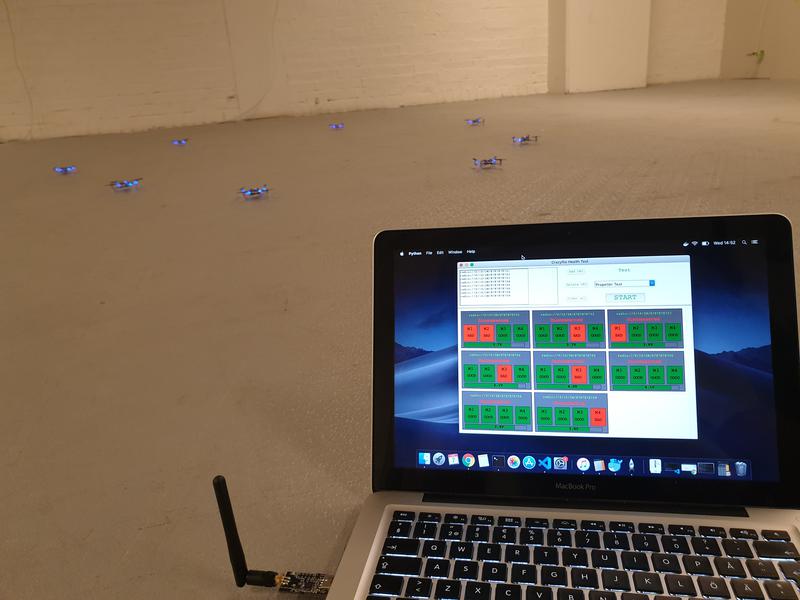
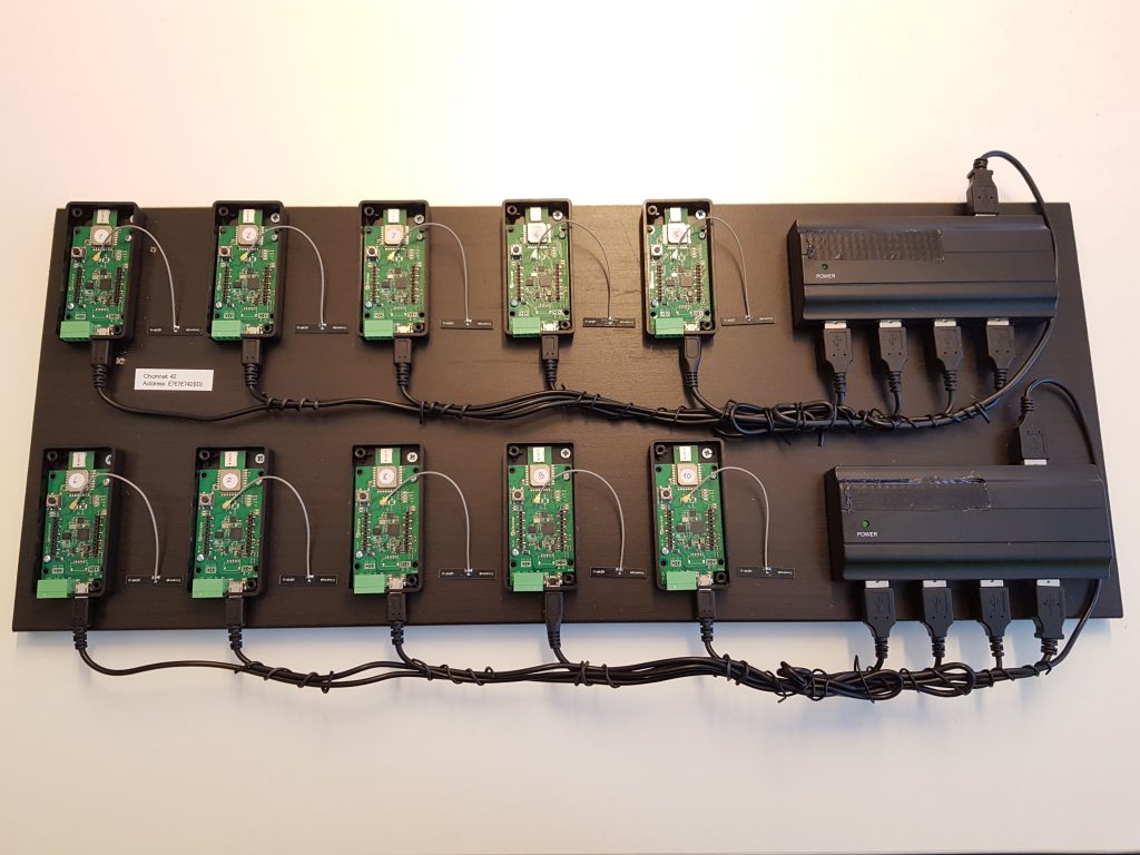
  • Communication base-station. SGBA by essence only needs one base-station Crazyradio PA, since all the behavior is completely on board. However, in order to show results in the paper, it was necessary for the CF to communicate information back, like odometry, state and such. As this was a two way communication (CFs needed RSSI to get back) each Crazyflie needed 1 base-station. Also, they all needed to be on different channels to avoid package collisions and RSSI accumulation.
  • Communication Peer to Peer. At development time, P2P didn’t exist yet, so we had to implement broadcast communication between the Crazyflies. Since the previous pointer required them to listen on different channels, the NRF had to be configured to send separate broadcast messages on all those channels as well. In order to time this properly, the home beacon had to sync the Crazyflies accordingly by sending out a timer. Even so, the avoidance maneuvers were done very conservatively to try to prevent inter-drone collisions.

Many of the issues, especially the communication challenges, will be solved with the updated code implementation as explained in the next section.

Updated code

The firmware that the Crazyflies used to fly in the experiments showed in the paper, can all be found in this public repository. However, the code is based quite an old version the current Crazyflie firmware, as it was forked almost a year ago. The implementation of the SGBA state machine and the P2P broadcasting were not generic enough to integrate this back to the development cycle, therefore the current code is only suitable for the old Crazyflie 2.0.

Therefore, we developed two major changes in the latest firmware which will make it much easier for me (and other ideas as well we hope!) to implement SGBA and the P2P communication in a way that should be compatible with any version of the firmware (and hardware) from here and on. We implemented SGBA as an app-layer and also handled all the broadcast messaging directly from this layer as well. Please check out this Github repository with this new app layer implementation of SGBA.

Over time the scope of Crazyflie has changed a lot. At first, Crazyflie was “just flying” with the only possible control was attitude (roll, pitch, yaw) and thrust setpoint sent from the Radio. Soon after, autonomous flight was investigated, first by implementing position controller outside Crazyflie and then, over time, moving position control on-board and sending position or trajectory setpoint to the Crazyflie. Now that the Crazyflie has good position control, the next step is to implement autonomous behavior and until now the most practical way is to do this from code running in an external computer. Similarly to what happened in the history of position control (first off-board and now onboard), it needs to be possible implement autonomous behavior in the Crazyflie itself. This blog post is about two newly implemented capabilities that will allow to implement automation in the Crazyflie firmware in an easy and maintainable way, namely the ‘App layer’ and the P2P communication.

App layer

The “App layer” is a term we have been using internally in Bitcraze to describe a set of functionalities that would allow to implement code in the Crazyflie. This includes the infrastructure to compile and maintain external code running in the Crazyflie as well as a set of API to control flight and behavior from C code rather than from radio communication.

Last week we implemented the first step of the App layer: the infrastructure part. It is now possible to build the Crazyflie firmware out-of-tree. This means that it is now possible, from a project, to point to the Crazyflie firmware folder and to compile a firmware from the project folder without touching the Crazyflie firmware folder. Practically it allows to create a git-repos implementing custom firmware code that has Crazyflie firmware as a sub-repos. This makes the maintenance of custom firmware code much easier than maintaining a branch of the Crazflie firmware as previously required.

A second piece that has been implemented is the app entry-point. It allows to start running code by just creating an “appMain()” function. The function will be called from a dedicated FreeRTOS task after the Crazyflie has initialized and started. This should make it much easier to get started.

For an example, we have extracted the multiranger push demo into a standalone git repos. This demonstrate the implementation of autonomous behavior using these new infrastructures.

Peer to Peer communication

The Crazyflie has been used for many research related to swarming, some examples are the crazyswarm project or the work done by Carnegie Mellon University. However, it is now time to turn it up a notch. On the forum and on the Github repository, there has been several request of enabling direct peer to peer communication to the Crazyflies. Now we finally found time to work on it and implement some basic functionality on the NRF and STM side of the firmware.

Currently, it is possible to send and receive a P2P packet in broadcast mode from the STM directly (see how to do this in the documentation). This enables data to be send from one Crazyflie to another with a maximum data size of 60 bytes. We were able to stress-test this with our test rig, by sending broadcast messages in a round-robin-kind of fashion, where the broadcast message was transferred through 10 Crazyflies in 10-20 ms. Even-though the current implementation is for now very minimal, we were able to fix some existing issues in the radiolink framework.

We will not stop there, as we are hoping to implement a communication system similar to how the CTRP protocol has been implemented. We are getting a lot of help by our active community members, so check out this github issue to be up-to-date with the current discussion.

CrazyFlies are great for indoor applications, thanks to their maneuverability and ubiquitous character. Its small size, however, limits sensor quality and compute capability. In our recent work we present source seeking onboard a CrazyFlie by deep reinforcement learning. We show a general methodology for deploying deep neural networks on heavily constrained nano drones, using full 8-bit quantization and input scaling. 

Our fully autonomous light-seeking CrazyFlie

Problem definition

Source seeking can be interesting in a variety of contexts. We focus on light seeking, as seen in nature. Many insects rely on light, either for survival or navigation. Light seeking in aerial robotics has many applications, such as finding the exit out of a dark room. 

Our goal is to fully autonomously find a light source, using only the onboard Micro Controller Unit (MCU) and deep reinforcement learning. 

Crazyflie configuration

Our fully autonomous nano drone uses several standard and custom sensors. We use the multiranger and flowdeck for position control and obstacle avoidance.

The Multiranger deck with our custom light sensor

We add a custom light sensor, based on the Adafruit TSL2591 sensor. The custom light sensor nicely fits in the multiranger deck, adding little mass and inertia (total vehicle mass is 33 grams).

CrazyFlie 2.1 with multiranger, flowdeck and light sensor

Algorithm

We use a deep reinforcement learning algorithm with a discrete action space. The neural network policy has laser rangers and light readings (current and past values) as input. The neural network tells the drone to rotate left, right or fly forward. We train a neural network with 2 hidden layers of both 20 nodes, featuring bias add and relu activation functions. The input layer is a vector with a length of 20 (4 states), which, compared to images, greatly reduces computational effort. 

DQN policy architecture

Simulation and conversion

We train our agent in simulation using the Air Learning simulation platform, after which we fully quantize the neural network to 8-bit integers.

To maintain accuracy after quantization, we have come up with quantization innovations. Both input layer and all tensors in the network need to have a pre-defined [min,max] range in float32, to convert to 8-bit integers. 

Air Learning pipeline

In the input layer, not all inputs have the same range. That is, a laser ranger can have values from 0 to 5 meters while our light sensor may return a value between 0 and 300 lux. To avoid this issue, we scale all inputs to the same range.

Additionally, the tensors in the network need to have an assigned [min,max] range for quantization. To achieve this, we input a range of representative input into the unquantized model, and read out the values of intermediate layers. With this strategy, we arrive at a 2.9x speed-up compared to float32 inference.

Implementation

We use Tensorflow Lite to deploy our tensorflow models in C on the CrazyFlie. The TFMicro Stack, together with the actual model, almost completely fill up the available RAM. 

RAM utilization on the CrazyFlie 2.1

The total amount of RAM available on the CrazyFlie 2.1 is 196kB, of which only 131kB is available for static allocation at compile time. The Bitcraze software stack uses 98kB of RAM, leaving only 33kB available for our purposes. The TFMicro stack takes up 24kB, thus leaving 9kB for the actual model (e.g., weights, bias terms). 

We also analyzed CPU usage, and noticed a high amount of interrupts by the ‘stabilizer’ thread, i.e., the PID controllers. Because of these interrupts, inference of our model takes 46.4 times longer than it would have been without interruption. 

Our quantized model is 3kB. If it were an FP32 model, it would have taken 12kB, which would not have fitted in the available memory. We were able to run inference at 4Hz, compared to the estimated 1.4Hz of the same but unquantized model. 

In a practical sense, we noticed a decreased level of stability when increasing model size. Occasionally the drone would reboot randomly while flying. Possible causes for this behavior are RAM overflow and task scheduling problems in RTOS. Besides, we observed variation in performance loss after quantization. Some of our trained models would just keep rotating after quantization, while our final model demonstrates robust source seeking behavior. This degree of uncertainty can possibly be avoided using quantization aware training. 

Finally, flying in a dark room without a position estimate can be challenging. The PID controllers heavily rely on information provided by the Flow Deck. This information is limited when little light is present while flying over a floor containing little features. To fix this, we added mats with texture on the ground, adding features and enabling stable flight in a dark room.

Flight tests

To validate our results in simulation, we created a cluttered environment with a light source. We randomly initialized the drone in the room, and hereby observed a success rate of 80% in a total of 105 flight tests. By varying the environment and initial drone position, we learned more about the inner workings of our algorithm.

Experiment testing environment

We learned that the algorithm performs better with more obstacles, and that a closer initial position improves performance. Generally, source seeking far away from the source seems really hard. Almost no variation in source strength exists between different measurements, and the drone observes mostly noise. 

Outlook

With our methodology, we were able to perform fully autonomous source seeking using deep reinforcement learning on a Cortex-M4 MCU. We hope our methodology will be applicable to other TinyML applications where resources are heavily constrained. Developing custom accelerators for a specific workload is time-consuming and expensive, while general purpose MCU’s are cheap and widely available. With our methodology, we unlock new applications for learning algorithms on heavily constrained platforms.

Direct path to source in empty room, blue = take-off

Links

Video: https://www.youtube.com/watch?v=wmVKbX7MOnU

Paper: https://arxiv.org/abs/1909.11236

Github: https://github.com/harvard-edge/source-seeking

Feel free to contact us might you have any questions or ideas: bduisterhof@g.harvard.edu

We are happy to announce that we have made new official releases of a number of our software components. The name of the release is 2019.09 and we have outlined the main changes below.

Crazyflie/Roadrunner firmware

  • Added support for the Crazyflie Bolt
  • Improved support for external positioning systems
  • Basic support for the Lighthouse positioning system
  • Added support for the Active marker deck
  • Improved debug support
  • Improved uSD card logging functionality
  • Bug fixes

For more details, please see crazyflie-release, crazyflie-firmware and crazyflie2-nrf-firmware.

Download the release package that you can flash with the client from crazyflie-release.

Python client and library

  • Basic Lighthouse support
  • More examples
  • Bug fixes

For more details, please see crazyflie-lib-python and crazyflie-clients-python. Note: the version of the crazyflie-lib-python is 0.1.8.

The Windows build of the python client has unfortunately been delayed but will be available soon.

LPS Node firmware

  • Improved menus
  • Bug fixes

For more details and download, please see lps-node-firmware


Kimberly and Arnaud is at IMAV in Madrid this week. Drop by the booth and check out the demo.

We have briefly mentioned the Active marker deck earlier in our blog and in this post we will describe how it works and what it is all about.

The Active marker deck is a result of our collaboration with Qualisys, a Swedish manufacturer of high end optical tracking systems. Optical tracking systems are often referred to as motion capture (mocap) systems and are using cameras to track markers on an object. By using multiple cameras it is possible to calculate the 3D position of the markers and the object they are attached to with very high precision and accuracy. It is common to use mocap systems in robotic labs to track the position and orientation of robots, for instance quadrotors.

Passive markers

The most common marker type is the passive marker, that is reflective spheres that are attached to the robot. By using infrared flashes on the cameras, the visibility of the markers is maximized and it makes it easier for the system to detect and track them. We are selling the Motion capture marker deck to make it easy to attach markers to a Crazyflie.

To get the full pose (position, roll, pitch, yaw) of a robot, the markers must be placed in a configuration that makes it possible for the mocap system to identify the orientation. This means that there must be some asymmetry in the marker positions to understand what is front, back, up, down and so on.

With a swarm of Crazyflies, unique marker configurations makes it possible to distinguish one individual from another and track all drones simultaneously. With a larger number of robots it becomes cumbersome though to place markers in unique configurations, and one approach to solving this problem is to have known start positions for all individuals and keep track of their motions over time instead. This solution is used in the Crazyswarm for instance and all Crazyflies can use the same marker configuration in this setup. Another approach is to make it possible to distinguish one marker from another, enter the Active marker deck.

Active markers

It is possible to use infrared LEDs instead of the passive markers, this is called active markers. The LEDs are triggered by the flash from the cameras and they are easily detected as strong points of light. Since they are emitting light they can be detected further away from the camera than a passive marker and the smaller physical size also keeps them more separated when they are far away and only a few pixels are available to detect them in the camera.

Furthermore Qualisys has a technology that makes it possible to assign an id to each marker and that enables the tracking system to identify individual markers and thus uniquely identify individuals in a swarm. With different IDs on the markers, there is no need have asymmetrical configurations and the marker layout can be the same on all drones. It also reduces the risk of errors in the estimated pose, since there is more information available.

The deck

The Active marker deck is designed to go on top of the Crazyflie and has four arms with one LED each. The arms are as long as possible to maximize the signal/noise ratio in the cameras, while still short enough to be protected from crashes by the motors. There is a STM32 F0 on the deck that takes care of the LEDs and handling of IDs and the main Crazyflie CPU does not have to spend any time on this.

The status of the deck is that the hardware is fully functional (we might want to move something around before we produce it though) and that there is a basic implementation of the firmware. IDs are assigned to the markers using parameters in the standard parameter framework in the client or from a script.

We will start production of the deck in the near future and it will be available in the store this autumn. Qualisys added support for rigid bodies using active markers in V2019.3 of the QTM tracking software.

Hello everyone, I’m Victor and you probably haven’t heard of me yet but I’ve got the awesome opportunity to spend some weeks during this summer working at Bitcraze. Working… Well, I’ve spent the majority of my time here getting invaluable experience, programming, flying with drones, eating incredible falafel and having fun so it’s really been a pleasure.

I’m quite new to both programming and electronics, so while I haven’t created any huge masterpieces of code yet, I did make a small program with a GUI that let you test the health of motors and propellers of the Crazyflie. You can run multiple ones simultaneously (I’ve tried up to 8, which works fine, even with a single radio, and you should be able to run many more) and it relies on using either Lighthouse or a Flow deck for positioning.
The propeller-test is essentially the same test as the one integrated with the cfclient, however the motor-test checks the thrust-levels of the motors (by hovering in the air for x seconds) to see if any of them are off and ranks them as good/bad. The default threshold is 15% but can be changed according to needs. The program is written in Python and uses tkinter to run the GUI application and the cflib to communicate with the Crazyflie. The script can be found here.

In the end of August I’m going to study Computer Science and Engineering which I’m extremely thrilled about and this has really been a perfect preparation for that! In the future I hope to contribute to the Crazyflie projects and learn more from the great team here at Bitcraze.

So until next time, fly safe!
Victor

Two weeks ago we posted about the demo we did for our new office move-in party. There has been multiple requests to share the script but unfortunately this is a hacked old script that is not going to be useful at all as an example. So, last week, we made an example that could run a synchronized swarm sequence.

The example has been pushed in the example folder of the Crazyflie-lib-python project. It is called synchronizedSequence.py. Running this example unmodified with 3 Crazyflies in a positioning system will give you this result. (Like the previous demo, this was done in a lighthouse system.)

One of the key design of the example is that it is based on a single control loop that can be synchronized with an outside system: in this example, there is a simple sleep of one seconds between each step of the sequence but it could for example be changed into a midi clock receiver to synchronize the sequence with music.

The example was developed with the help of Victor, a student we have hired to help-out during the summer. He has then played around a little bit to make a 9 Crazyflies sequence that is more impressive:

I uploaded Victor’s sequence in a github gist as it can be good for inspiration. One bit of warning though: as is, the sequence contains some vertical movements that are quite aggressive and the part where Crazyflies fly directly on top of each-other is more to be considered as a stress test.

Summer is here and temperatures are rising. Since many of us will be on holidays, we will focus this quarter on a special summer clean up! See here what we are working on:

  • Fixing issues: This time we are aiming to close many of the issue tickets in our Github repositories, so that after the summer everything will run much more smoothly (we hope!). Definitely our test rig will come in very hand to sniff out more issues in terms of radio communication as well. You can help as well! Everybody who is using and developing on with the STM-firmware, NRF-firmware or python library, or anything else and is noticing issues, please make a ticket in that same Github repository (if you are familiar with the code) or post about it on our forum (if you do not know exactly what is going on). Together we can make the code better.
  • Lighthouse calibration: In March we released our lighthouse deck for positioning with the HTC Vive base stations. We did feel that the setup process could be improved further, since currently, the Crazyflies’ firmware must contain hardcoded information of the Steam VR’s base station position. We will try to apply the factory calibration direct from the Base stations itself. This will enable us to do 2 additional things: (1) The Crazyflie with the LH deck itself could be used to setup the Lighthouse system, so that SteamVR would not be necessary anymore. (2) Only 1 base station is needed for positioning instead of 2, which will improve the robustness in case of loss of visual-line-of-sight of one base station.
  • Documentation: We try to provide all the possible information for everybody to be able do anything they want with their Crazyflie. But with high flexibility comes great responsibility…. for proper documentation! We are planning to restructure all of our media outlets and try to improve the flow and level of detail for our users. We hope to make it easier for beginning developers to get started and more advanced developers to gain better understanding of the system in order to implement their own awesome ideas. So our very first step is to restructure and clean up the Bitcraze wiki and see where we can add more content.
  • Products: We have a lot of products coming out in the 2nd half of the year
    • AI Deck: We are working hard to get the AI deck all ready for production and we are estimating that they will be available for early access in late autumn. Keep a look out on our forum for regular updates on the progress!
    • Lighthouse breakout board: We made our first working prototype of the lighthouse breakout board, which should make it easier for the lighthouse positioning system to also work on other platforms than the Crazyflie.
    • Active Marker Deck: We are very much on on track with the Qualisys active marker deck! It should be available in the Autumn.
    • Crazyflie Bolt: This has been send off to production for the early access version, which should be available in the Autumn!

Many of our users are flying larger and larger swarms and we’ve been getting some feedback that there’s communication issues when connecting to many Crazyflies. So during the last weeks we’ve been looking at this. Among the things we’re doing is building a test rig where we can automate the communication testing (last weeks blog post). We’ve also fixed a few communication issues listed below.

One of the issues causing problems is dropping packages coming in to the Crazyflie. If the flow of packages was too high to one CRTP port these would start dropping. This has now been fixed by increasing the length of the queues for each port. (GitHub issue)

Another issues has been logging data piling up after disconnect. The detection for the radio disconnection was boken so logging data would continue to be generated and pushed into the communication stack. This has now been fixed so logging will be reset which should clear up he congestion on the next connect. (GitHub issue)

Lastly we also fixed the USB communication issue with dropped packages and crashing when the USB was disconnected. (GitHub issue)

We’ve already noticed a few other issues when using the rig so there should be more fixes coming soon. In the meantime test out the new firmware and let us know if there’s still issues.

While running our ICRA demo, we came across a bug in the Crazyflie python-lib radio handling, limiting the number of Crazyflie that could be controlled using one Crazyradio PA. Communication with many Crazyflies is crucial as flying swarms is becoming more of an interesting topic for research and education. So we decided to take the problem at hand and create a radio test-bench:

To make the test-bench we have attached 10 roadrunner boards to a plank of wood together with USB switches that can provide enough power to the roadrunners. We used the roadrunner because it is mechanically easier to use in this context and it has an identical architecture to the Crazyflie 2.1 when it comes to the radio implementation.

Initially we will use the test-bench to run test scripts that pushes the communication to its limits and that consistently test the communication stack functionalities. This should allow us to find bug and verify that we solve them as well as discovering and documenting limitations.

Eventually we want to connect a raspberry-pi to the test-bench and run tests for each commit and pull-request to the crazyflie-firmware, crazyflie2-nrf-firmware and crazyflie-lib-python projects. This will guarantee that we do not introduce new limitations in the communication stack. The test-bench will also be very useful in implementing new functionalities like direct crazyflie-to-crazyflie P2P communication.

As a final note, the Crazyswarm project is not affected by the Crazyflie-lib bug since it is using the C++ implemented crazyflie-ros driver. Hence Crazyswarm can control more Crazyflies per Crazyradio PA, so it is still the preferred way to fly a swarm mostly when using a motion capture system. Though, with the progress made on LPS and Lighthouse positioning, running swarms, using the python API directly is a probably a more lightweight alternative.