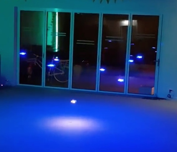
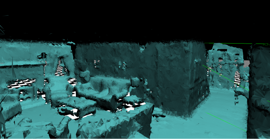
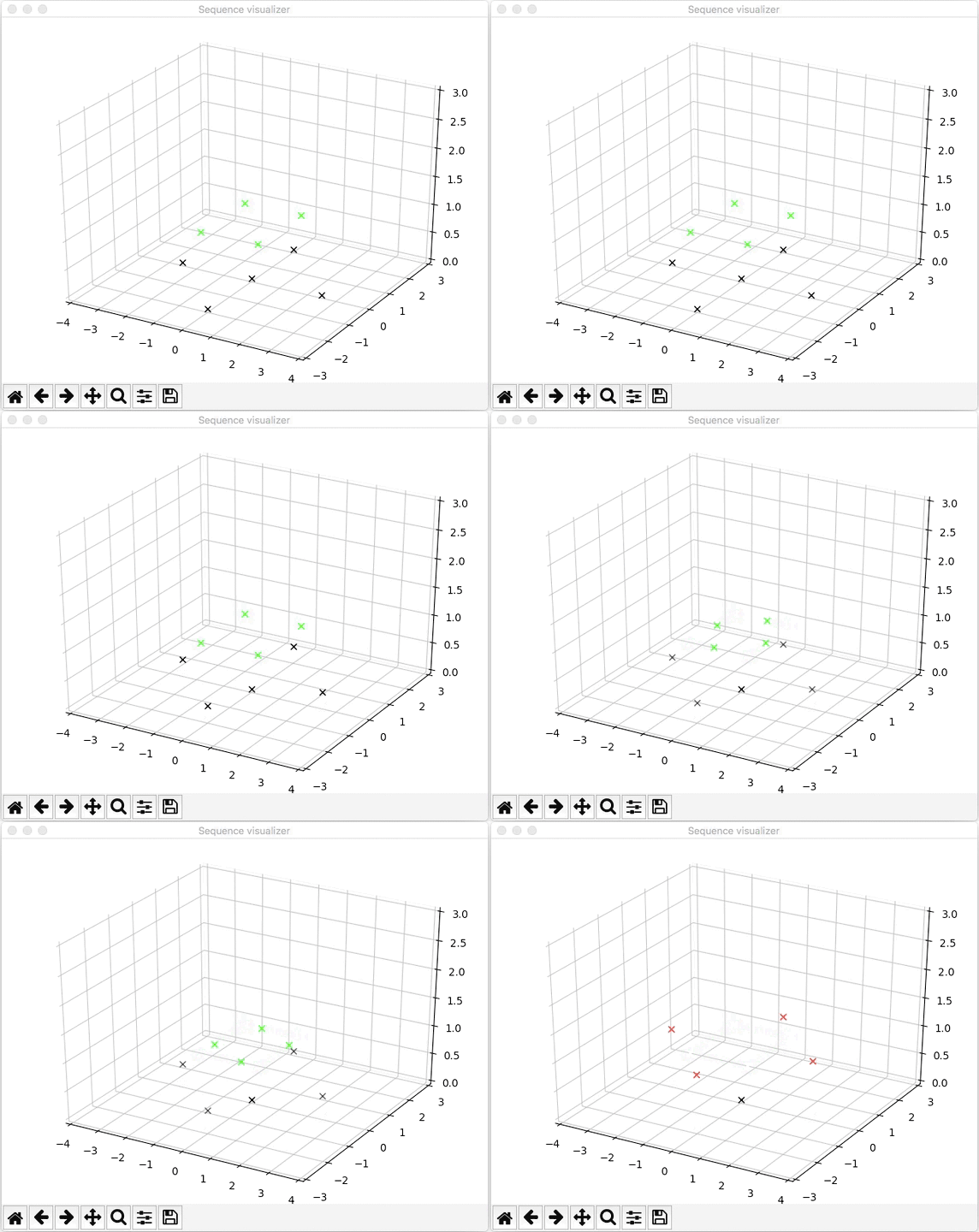
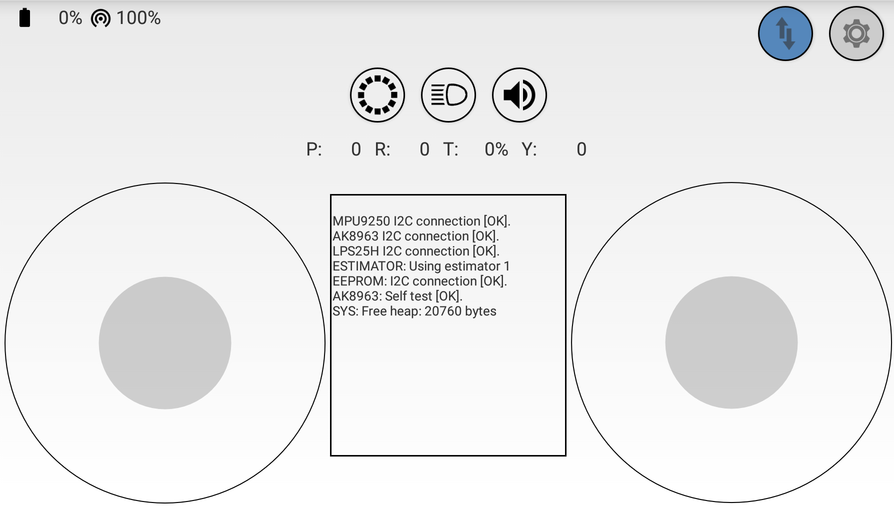
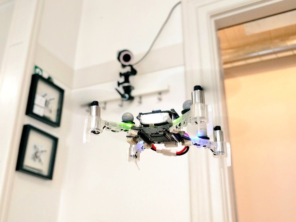
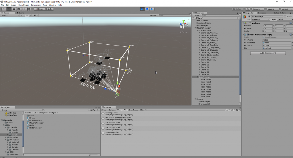
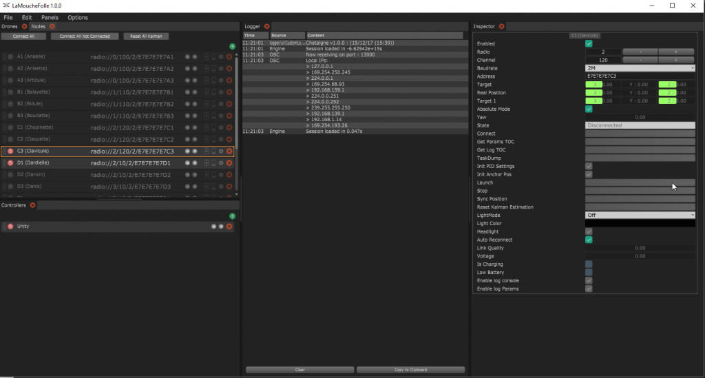
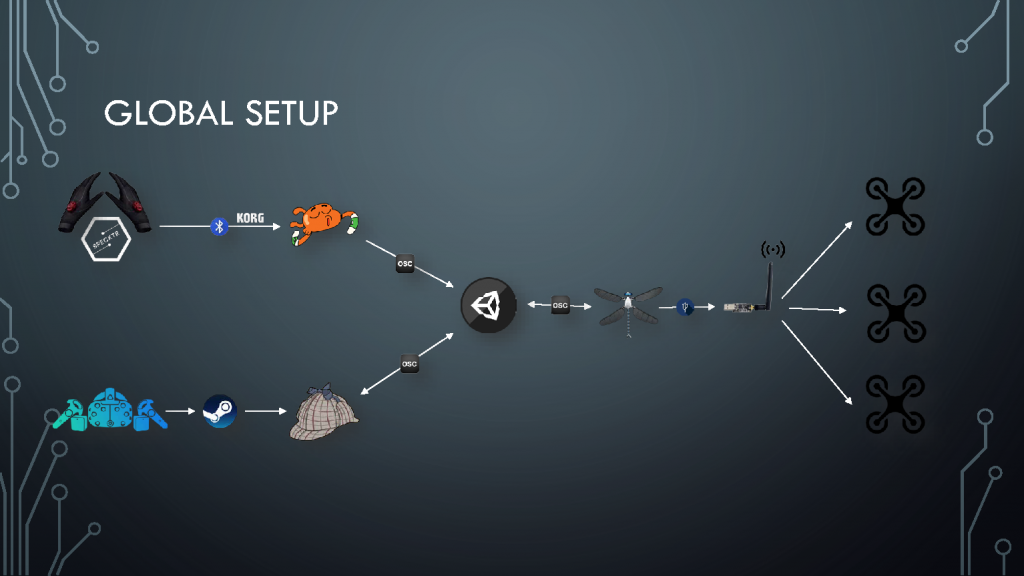
We’ve been seeing an increase in the demand for a “programmable drone”, where users can easily give simple commands though scripting and the Crazyflie 2.0 following them. In order for this to work well you need a closed-loop control, i.e you need a reference system to see how you’re moving. Previously this was only possible using external camera systems or bulky on-board cameras. But a while ago we released the Flow deck which solves this problem. Thanks to the mouse-like sensor the deck contains it enables the Crazyflie 2.0 to see how it’s moving along the floor. Suddenly it’s possible to give commands like “move 1 m forward” or “fly in a clock wise circle with the radius of 1 m”.
To make it easier for users to pick out the parts needed we’ve put together a discounted STEM drone bundle. It contains all the parts needed for scripting the flight. If you have a gamed-pad or a Bluetooth LE enabled phone you can of course fly it manually as well :-)
The Loco Positioning System (LPS) default working mode is currently Two Way Ranging (TWR), it is a location mode that has the advantage of being pretty easy to implement and gives good positioning performance for most use cases and anchor setups. This was a very good reason for us to start with it. Though, TWR only supports positioning and flying of one or maybe a couple of Crazyflies, while it is not a solution to fly a swarm.
One solution to fly a swarm is an algorithm called Time Difference of Arrival (TDoA). We have had a prototype implementation for a while but we experienced problems with outliers, most of them where due to the fact that we where loosing a lot of packets and thus using bad data.
To solve these issues, TDoA2 makes two changes:
Each packet has a sequence number and each timestamps is associated with the sequence number of the packet it has been created from
The distances between anchors are calculated and transmitted by the anchors
A slightly simplified explanation follows to outline why this helps (a more detailed explanation of how TDoA works is available in the wiki).
We start by assuming that all timestamps are available to the tag, this is done by transmitting them in the packets from the anchors to the copter.
The end goal is to calculate the difference of time of arrival between two packets from two different anchors. Assuming we have the transmission time of the packets in the same clock, all we need to do is to subtract the time between the two transmissions with the time between the two receptions:
0 – anchor 0, 1 – anchor 1, T – Tag (that is the LPS deck on the Crazyflie)
To do so we need to have the time it took for the packet to travel between the two anchors, this will enable us to calculate the transmit time of P2 in anchor 1, this can be done by calculating the TWR time of flight between the two anchors, this would require the tag to receive 3 packets in sequence:
So now for the part where TDoA2 helps: previously we had to have the 3 packets in sequence in order to calculate a TDoA, if any one of these where missing the measurement would fail or worse, it could give the wrong result. Since we did not have sequence numbers, it was hard to detect packet loss. Now that we have sequence numbers, we can understand when a packet is missing and discard the faulty data. We also do not have to calculate the distance between anchors in the tag anymore, it is calculated by the anchors themselves. This means that we can calculate a TDoA with only two consecutive packets which increases the probability of a successful calculation substantially.
To reduce packet loss even more, we have also added functionality to automatically reduce the transmission power of the NRF radio (the one talking to the Crazyradio dongle) when the LPS deck is detected. It has turned out that the NRF radio transmissions are interfering with UWB radio reception, and since most indoor use cases does not require full output power we figured that this was a good trade-off.
The results we have seen with the new protocol is quite impressive: TDoA is usually very sensitive to the tag being inside the convex hull, so much so that with the first TDoA protocol we had to start the Crazyflie from about 30cm up to be well within the convex hull. This is not required anymore and the position is still good enough to fly even a bit outside of the convex hull. The outliers are also greatly reduced which makes this new TDoA mode behave very close to the current TWR mode, but with the capability to locate as many Crazyflies as you want:
Added to that, we have also implemented anchor position handling in the TDoA2 protocol and this means that it is now as easy to setup a system with TDoA2 as with TWR:
We are now working on finishing the last functionality, like switching between algorithms (TWR and TDoA) and on writing a “getting started guide”. When that is done TDoA will become an official mode for the LPS.
In the mean time, if you are adventurous, you can try it yourself. It has been pushed in the master branch of the Crazyflie firmware and the LPS node firmware. You should re-flash the Crazyflie firmware, both STM32 and nRF51, from master and the anchors from master too.
As I wrote about in a previous blog post, I have been working on an anchor position estimation algorithm in the Crazyflie Client. The algoritm uses ranging data from the Loco Positioning system to estimate where the anchors are located, and thus remove the need to measure their positions in the room. I have finally reached a point where I think it is good enough to let it out from the lab and it has been pushed to the client repository.
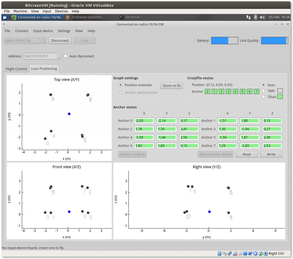
A button has been added to the Loco Positioning tab that opens a wizard. In the wizard the user is asked to place the Crazyflie in certain positions to record ranges and define the coordinate system. If all goes well, the estimated anchor positions are transfered to the anchor position fields in the Loco Positioning tab. If the user is happy with the result the next step is to write the positions to the anchors and start flying!
Now to the disclaimer: the results may not always be perfect – surprise! We have not tested the algorithm a lot but it seems to give decent results, at least it can be useful as a base for manual corrections and sanity checks. Some of the estimated positions are pretty good, while others might be a meter or so off. The conclusion is that you should not trust it blindly, check that the estimated positions seem reasonable before flying.
Currently the system only supports Two way ranging, but extending it to TDoA should not be too complicated. There are probably many possible improvements that can be done, and we hope that everyone that finds this interesting and have ideas of how to do it will give it a go. After all, it is open source and we would love to see contributions refining the functionality, now that there is a base to build from.
Any feed back is welcome, let us know if it works or not in your setup!
It has been a while since we have made a blog post about the the community and quite a lot has happened, and is about to happen, so we though we would do an update for this Monday post.
Fred, the Crazyflie android client community maintainer was visiting us last week. He is making great progress on the Java Crazyflie lib that is going to be used in the Android client as well as in PC clients. The lib is still experimental but when finished it will allow to connect and use a Crazyflie from any Java program, there has already been some successful experimentation done using it from Processing.
Thanks to Sean Kelly, the Crazyflie 2.0 is now officially supported by the Betaflight flight controller firmware. Betaflight is a flight controller firmware used a lot in the FPV and drone racing community. This is the announcement by theseankelly in the forum:
Betaflight 3.2 was officially released this month. This is the first release that contains the Crazyflie 2.0 target by default, so you don’t need to clone and build from source anymore. It’s available as a target in the betaflight configurator from the google chrome store! I’ve tested it out and it works as expected. Haven’t tested the BigQuad variant, but that’s also available in the app by default.
The Crazyswarm project, by Wolfgang Hoenig and James A. Preiss from USC ACTlab has been presented at ICRA 2017. It is a framework that allows to fly swarms of Crazyflie 2.0 using a motion capture system. There is currently some work done on merging the Crazyswarm project into the Crazyflie master branch, this will make it even easier to fly a swarm of Crazyflie. In the meantime the project is well documented and can be used by anyone that has a couple of Crazyflies and a motion capture system.
One of the pain points when setting up the Loco Positioning system is to measure the anchor positions and enter them into the system. I wanted to see if I could automate this task and let the system calculate the positions, and if so understand what kind of precision to expect. I have spent a few Fun Fridays playing with this problem and this is what I have found so far.
The problem can be broken down into two parts:
1. How to calculate the anchor positions. What data is required?
2. How to define the coordinate system. To make it useful the user must to be able to define the coordinate system in a simple way.
How to calculate the anchor positions
The general idea of how to calculate the anchor positions is to set up a system of equations describing the distances between the anchors and/or the Crayzflie and solve for the anchor positions. The equations will be non linear and the (possibly naive) plan is to use the Gauss Newton method to solve the system.
To understand how to calculate the anchor positions we must first take a look at the data that is available. The Loco Positioning system can be run in two different modes: Two Way ranging (default mode) and TDoA.
Two way ranging
In the Two Way ranging mode we measure the distance between each anchor and the Crazyflie and to get enough data we must record ranging data for multiple positions. The anchor positions are unknown, and for each new Crazyflie position we add yet a new unknown position, on the other hand we measure the ranges to the anchors so these are knowns.
The equations used are simply to calculate the distance between the assumed position of each anchor and the Crazyflie and then subtracting it from the measured distance.
TDoA
In TDoA we measure the Time Difference of Arrival, that is the difference in distance to two anchors from the Crazyflie’s position. It is probably possible to use this information, but I was looking for a different solution here. In our new TDoA implementation that we have been playing with a bit, we get the distance between all anchors (calculated in the anchors) as a side effect.
In this case the Crazflie is not really needed and the equations describe the distance between assumed anchor positions versus measured distances.
How to define the coordinate system
To get a useable positioning system, the coordinate system must be well defined and oriented in a practical direction. For example when writing a script you probably want (0, 0, 0) to be at some specific spot, the X-axis pointing in a certain direction, the Z-axis to point up and so on. My initial idea was to use the anchors to define the coordinate system, use anchor 0 as (0, 0, 0), let the X-axis pass through anchor 1 and so on. Just by looking at our flight lab I realised that this would be too limiting and decided that the coordinate system should be completely disconnected from the anchor positions, but still easy to define. I also realised that a really good way to tell the system about the desired coordinate system would be to move the Crazyflie around in space to show what you want. The solution is to place the Crazyflie at certain positions and click a button to record data at these positions. The steps I have chosen are:
Place the Crazyflie at (0, 0, 0)
Place the Crazyflie on the X-axis, X > 0
Place the Crazyflie in the XY-plane, Y > 0
Move the Crazyflie around in the space with continuous recording of data
In this scheme the XY-plane is typically the floor.
Results
I have written basic implementations for both the Two Way ranging and TDoA modes and they seem to work reasonably well in simulations. I have also tested the Two Way ranging algorithm in our flight lab with mixed results. The solution converged in most cases but not always. When converging the estimated anchor positions ended up in the right region but some were off by up to a meter. Finally I did run the algorithm and fed the result into the system and managed to fly using the estimated positions which I find encouraging.
I will continue to work on this as a Friday Fun project and maybe it will make its way into the client code base at some point in the future? There are probably better ways to estimate the anchor positions and more clever algorithms, feel free to share them in the comments.
A few weeks ago we wrote about a new prototype that we call “the obstacle avoidance deck”. Basically it’s a deck fitted with multiple VL53L0x ToF distance sensors that measures the distance front/back, right/left and up of the Crazyflie 2.0. Combined with the Flow deck this gives you an X/Y/Z robot that you can program fly around avoiding obstacles which doesn’t need any external positioning system.
After implementing firmware support for the deck (see #253 and #254) we’ve finally had a chance to do some initial testing, see the video below. In the current implementation we’re doing the measurements in the firmware but using the logging framework to get all the distances into a Python script which does the movement control. Since we have the Flow deck attached we can control the Crazyflie 2.0 in velocity mode, which means we can say things like “Go forward with 0.5 m/s until the forward sensor shows a distance lower than 50cm” or “Go forward 1 m/s for 1s and rotate to measure the distance to all objects”. Since there’s no real-time requirements we can move the complexity of the algorithm from the firmware into external scripting which makes it a lot easier to develop. Now we’re really eager to start setting up obstacle courses and time how fast we can move though them :-)
The results from the testing shows that our two main concerns aren’t an issue: The sensors doesn’t seem to interfere with each other and we can sample them all at high-enough frequency without occupying the bus too heavily (currently we’re doing 20Hz). The next step is figuring out the requirements (i.e how many VL53L0x sensors are needed, do we really need the back one?) and a mechanical solution for attaching the sensors in production. If there’s any feedback let us know now and we’ll try to get it into the design. Also, we really need a new name for the board. Any suggestions?
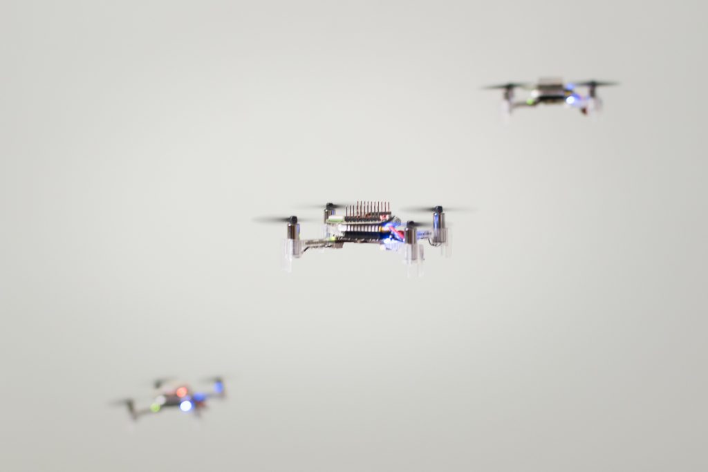
We have had an implementation of a Time Difference of Arrival algorithm (TDoA) in the Crazyflie 2.o and the Loco Positioning System for quite a long time. The coolest feature of the TDoA algorithm is that it can be used to position virtually unlimited number of Crazyflies concurrently as opposed to the standard Two Way Ranging algorithm that is limited to one (or very few Crazyflies). The original implementation is working pretty well but contains some flaws that we are not completely happy with, hence we have not released it officially and are still calling it experimental. Since support for tracking multiple objects is a requirement for flying swarms and we like swarms, we have started to iron out the problems.
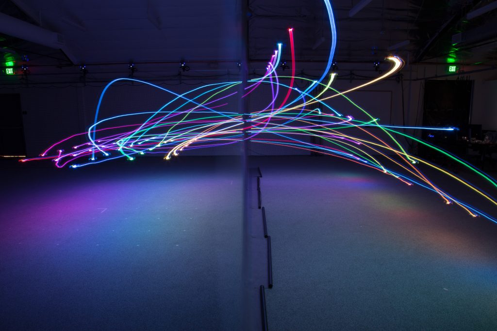
A small swarm using the old TDoA algorithm, from February 2017.
In the current implementation each anchor transmits the time of the transmission and the times of the latest reception of transmissions from all other anchors about every 16 ms. From this information it is possible to calculate the difference in time of flight for the radio waves from two anchors to the Crazyflie. When we know the difference in time of arrival, by multiplying with the speed of light we get the difference in distance and can calculate the position of the Crazyflie. This all sounds fine and dandy but the set up has some problems, the biggest one being error handling. If one or more packets are lost, either from anchor to Crazyflie or anchor to anchor, there is no deterministic way to detect it in some cases. The current algorithm relies on sanity checking the calculated result and discarding data that looks suspicious, which is usually easy as the distances quickly gets unrealistic (several thousands of meters!). We suspect that some erroneous values slip through the check though and we would like to be able to really understand when data is valid or not.
TDoA 2.0
What we are working on now is to add a sequence numbering scheme to enable the receiving party to understand when a packet has been lost. With this information it will be possible to discard bad data as well as use the available information better. While we are re-writing the code we are also moving a part of the algorithm from the Crazyflie to the anchors, after all there is a CPU in the anchors that is not fully utilized. The idea is to let each anchor continuously calculate the distance to all other anchors and add this information to the messages it transmits, which will reduce the work in the Crazyflie.
This is work in progress and we are not completely sure where we will end up, but we are aiming at making the TDoA mode part of the official release at some point.
Sensor fusion
Related to the Loco Positioning system is our line of other positioning sensors; the Z-ranger deck and the Flow deck. The Flow deck has really good precision at low altitudes but can not provide absolute positioning while the Loco Positioning system does not have the same precision but absolute position capabilities. So what if we fuse the information from the Flow deck with the Loco Positioning system? We have tried it out and it works pretty well, we can get the best of two worlds! The Z-ranger can also be used in the same way to improve the Z component of the estimated position when flying bellow ~1m.
Even though it works using multiple positioning sensors at the same time, there is room for improvements and some tweaking will be required to make it rock solid.
The Crazyflie, the original one, usually called Crazyflie 1 to avoid confusion, was the first commercially available open source nano quadcopter back in 2013. After getting feedback on the platform and having a lot of ideas of things that could be improved, we developed the Crazyflie 2.0 during 2014 and released the same fall. We decided we wanted to keep full backward compatibility with Crazyflie 1, both in the firmware project and in the different clients and support libraries even though we now had more processing power and RAM.
But during the last year we’ve almost exclusively been adding functionality that is Crazyflie 2.0 specific, while still trying to stay inside the constraints of the Crazyflie 1. We’ve also seen a decline in the discussions and interest of the Crazyflie 1. So this week when we once again broke the build because we run out of RAM in the Crazyflie 1, we decided to remove the Crazyflie 1 support from the Crazyflie firmware project. It’s of course with a heavy heart we do this, but we feel that in order for the Crazyflie 2.0 to move forward it’s a must. The last release that’s compatible with the Crazyflie 1 is 2017.6.
But if you’re still using the Crazyflie 1, don’t worry we’re not completely dropping it, we will continue to carry spare parts and if anyone wants to continue firmware development we will be happy to assist. If anyone is motivated, the code can be branched from the last release and we could make a new repository to host the Crazyflie 1 code.
It is summer again in Sweden and things are now starting to slow down and people are going to vacation. The last couple of years we have used the summer to look back and clean-up the technical dept accumulated during the year: when trying to get things done we have to prioritize which means that some things have to be left on the side (at least until we invent a way to add more hours to each day). This year is no exception, the last couple of weeks we have been working very hard to get the Flow products out and now the production is hopefully on rails so the cleanup can begin.
There is a lot of things we could do but here is a sneak peek of what we are currently looking at:
Crazyflie Client gamepad handling and configuration: The current input device handling is complicated and the architecture is hard to work with. There is a lot that can be done both in the front-end and the back end to make it easier to use and to work with.
Loco positioning system support for multiple Crazyflie, we have two mode implemented for that, TWR-TDMA and TDoA, both are very experimental and need some more work.
Cleanup of the webpage, information and documentation: we already have done a lot of work to make better documentation but there is always margin for improvement.
Cleaning up and improving the Crazyradio firmware: the Crazyradio starts to show its limits when flying swarms of Crazyflie. There is some improvement that could be done in the Firmware to make it more efficient. The first step is clean up the current implementation.
If you have any ideas of areas you feel we should focus on, even better if you want to help with some things and fix it together with us, just tell us in the comment.
On a side note, the manufacturing of the Flow products is still on progress and it should soon be on the Bitcraze shop and the Seeedstudio bazaar, stay tuned.
Robots that can both fly and drive – in particular wheeled drones – are actually somewhat of a rarity in robotics research. Although there are several interesting examples in the literature, most of them involve creative ways of repurposing the wings or propellers of a flying robot to get it to move on the ground. Since we wanted to test multi-robot algorithms, we needed a robot that would be robust, safe, and easy to control – not necessarily advanced or clever. We decided to put an independent driving mechanism on the bottom of a quadcopter, and it turns out that the Crazyflie 2.0 was the perfect platform for us. The Crazyflie is easily obtainable, safe, and (we can certify ourselves) very robust. Moreover, since it is open-source and fully programmable, we were able to easily modify the Crazyflie to fit our needs. Our final design with the wheel deck is shown below.
A photo of the Crazyflie 2.0 with the wheel deck.
A model of the Crazyflie 2.0 with the wheel deck from the bottom
The wheel deck consists of a PCB with a motor driver; two small motors mounted in a carbon fiber tube epoxied onto the PCB; and a passive ball caster in the back. We were able to interface our PCB with the pins on the Crazyflie so that we could use the Crazyflie to control the motors (the code is available at https://github.com/braraki/crazyflie-firmware). We added new parameters to the Crazyflie to control wheel speed, which, in retrospect, was not a good decision, since we found that it was difficult to update the parameters at a high enough rate to control the wheels well. We should have used the Crazyflie RealTime Protocol (CRTP) to send custom data packages to the Crazyflie, but that will have to be a project for another day.
The table below shows the mass balance of our miniature ‘flying car.’ The wheels added 8.3g and the motion capture markers (we used a Vicon system to track the quads) added 4.2g. So overall the Crazyflie was able to carry 12.5g, or ~44% of its body weight, and still fly pretty well.
Next we measured the power consumption of the Crazyflie and the ‘Flying Car.’ As you can see in the graph below, the additional mass of the wheels reduced total flight time from 5.7 minutes to 5.0 minutes, a 42-second or 12.3% reduction.
Power consumption of the Crazyflie vs. the ‘Flying Car’
The table below shows more comparisons between flying without wheels, flying with wheels, and driving. The main takeaways are that driving is much more efficient than flying (in the case of quadcopter flight) and that adding wheels to the Crazyflie does not actually reduce flying performance very much (and in fact increases efficiency when measured using the ‘cost of transport’ metric, which factors in mass). These facts were very important for our planning algorithms, since the tradeoff between energy and speed is the main factor in deciding when to fly (fast but energy-inefficient) versus drive (slow but energy-efficient).
Controlling 8 Crazyflies at once was a challenge. The great work by the USC ACT Lab (J. A. Preiss, W. Hönig, G. S. Sukhatme, and N. Ayanian. “Crazyswarm: A Large Nano-Quadcopter Swarm,” ICRA 2017. https://github.com/USC-ACTLab/crazyswarm) has made our minor effort in this field obsolete, but I will describe our work briefly. We used the crazyflie_ros package, maintained by Wolfgang Hönig from the USC ACT Lab, to interface with the Crazyflies. Unfortunately, we found that a single Crazyradio could communicate with only 2 Crazyflies at a time using our methods, so we had to use 4 Crazyradios, and we had to make a ROS node that switched between the 4 radios rapidly to send commands. It was not ideal at all – moreover, we had to design 8 unique Vicon marker configurations, which was a challenge given the small size of the Crazyflies. In the end, we got our system to work, but the new Crazyswarm framework from the ACT Lab should enable much more impressive demos in the future (as has already been done in their ICRA paper and by the Robust Adaptive Systems Lab at Carnegie Mellon, which they described in their blog post here).
We used two controllers, an air and a ground controller. The ground controller was a simple pure pursuit controller that followed waypoints on ground paths. The differentially steered driving mechanism made ground control blissfully simple. The main challenge we faced was maximizing the rate at which we could send commands to the wheels via the parameter framework. For aerial control, we used simple PID controllers to make the quads follow waypoints. Although the wheel deck shifted the center of mass of the Crazyflie, giving it a tendency to slowly spin in midair, overall the system worked well given its simplicity.
Once we had the design and control of the flying cars figured out, we were able to test our path planning algorithms on them. You can see in the video below that our vehicles were able to faithfully follow the simulation and that they transitioned from flying to driving when necessary.
Our work had two goals. One was to show that multi-robot path planning algorithms can be adapted to work for vehicles that can both fly and drive to minimize energy consumption and time. The second goal was to showcase the utility of flying-and-driving vehicles. We were able to achieve these goals in our paper thanks in part to the ease of use and versatility of the Crazyflie 2.0.