In this beginning of 2017 we are proud to announce that there are two new decks for the Crazyflie 2.0.
The first one has been in the works for quite some time, it is the Micro SD card deck. It enables read and write access to a SD-Card from the Crazyflie firmware (where we have also implemented FAT filesystem support). Our first use case for this deck has been to implement high speed logging of the IMU sensors: the SD-Card has much higher bandwidth than the radio so it allowed us to log all the sensor values for later analysis. Another use-case could be to read an autonomous sequence from a file on the SD-Card and implement fully autonomous sequencing in the Crazyflie when used in the Loco Positioning System for example. The SD-Card deck is already available on Bitcraze web-shop.
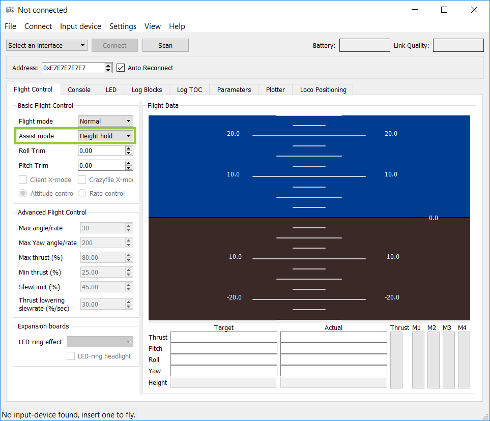
The Second deck is the Z-Ranger deck, it is a laser time-of-flight ranging deck that measures the distance to the ground. We talked about this deck in a previous post. The manufacturing of the deck should be finished soon and so it will be available in our shop shortly. When using this new deck, the altitude hold stability between 0 and 1.5 to 2m height is greatly improved.
On a final note, FOSDEM 2017 is this coming up this weekend and we are looking forward to meet you there. There will be two presentations related to the Crazyflie, if you want to meet us come at these presentations or get in touch in the comment or by mail. The two presentations are:
Quite a lot has happened in the community in the latest month so we though we would dedicate this Monday post to you :-).
On the firmware side, the loco positioning system has sparked a lot of contribution. Most prominently is the Extended Kalman Filter by Mike Hammer and later improvement by multiple contributors. The Crazyflie is getting more stable and capable week after week which is awesome. Wolfgang from USC has also pushed enhancement coming from its CrazySwarm which will one day gives to everyone the capability to fly big Crazyflie swarm more easily.
On the clients side, we just pushed a new version of the iOS app to the app-store. The main improvement is the new tilt control mode implemented by EMart002 and beta-tested by a community member.
There has also been a new release of the Android client by Fred. This new version adds support for log and param using the Crazyradio. This way it is possible to get telemetry from the Crazyflie like the battery voltage and there is an experimental implementation of altitude-hold when using gamepad.
Running a beta (test-flight) version for the iOS client has been a good experience as it allowed to get direct feedback on functionalities. If there is interest we could release and announce beta versions for both Android and iOS in the future.
Finally last but not the least, there will be a new Crazyflie client in town: The Crazyserver created by Mike Hamer and written in go. It is a cross-platform, install-less, dependency-less server for a fleet of Crazyflies. It exposes a language-independent API, an HTTP rest API, to be able to connect and control any number of Crazyflie from any programming language. It will also include sockets (UDP, TCP and Websockets) to carry real-time data like setpoint and telemetry. It is still very much work in progress and not ready for real-world usage but if you are curious and/or would like to help check the code is on github.
Last week we reached a milestone for our Loco Positioning System: we got 5 Crazyflie 2.0 to fly in a swarm with Time Difference of Arrival measurements. This is a great step closer to making the LPS leave the early-access state.
Until now, positioning has been done using a method called Two Way Ranging (TWR). The advantage of TWR ranging is that it allows us to easily get ranges to the anchors by actively pinging them in sequence. Based on these ranges we can then calculate the current Crazyflie position and control the Crazyflie to move to a wanted position. The big drawback though is that since each Crazyflie has to actively transmit packets to ping anchors, flying many Crazyflie means sharing the air and so the more we want to fly the less ranging each Crazyflie can do. In other words: it does not scale.
TDoA measurement consist of measuring the difference of flight time between packets coming from different anchors and this is harder to achieve since the anchor clocks must be synchronized to each other. The killer feature of TDoA is that it can be implemented using unidirectional packet sent from the anchor system and received by the tag/Crazyflie. It means that as soon as you get one Crazyflie flying with TDoA, you can get as many as you want since the Crazyflies do not have to transmit anything.
This is what happened last week: on Thursday evening we got 1 Crazyflie to fly with TDoA measurements. On Friday we tried 3 and then 5 without much effort. It was just matter of modifying the ROS launchfile to connect more crazyflies, a copy-paste operation.
There still seems to be a margin for progression to get even more stable flight with TDoA and we are also working on making the LPS and Swarm work with our Python client which will make it easier to use outside a robotic lab.
If you want to try the (very experimental!) TDoA mode with your loco positioning system we have documented how to get it to work on the wiki.
Thanks a lot to the growing community that is supporting us and allow us to move faster towards a Crazyflie swarm.
Last week was interrupted, disrupted and generally chopped up as a few of us had to stay home fighting germs and viruses. Today all of us were present again and hopefully we will all be well this week to participate in the fun. Even though last week will not make it to the hall of fame when it comes to productivity we still made some progress.
TDoA mode of the Loco Positioning system
We are happy to announce that we have calculated the first TDoA (Time Difference of Arrival) based position in the Crazyflie. This might not sound very spectacular but it is one step closer to being able to position an infinite (in theory) number of Crazyflies simultaneously. We used test driven development (TDD) to implement the functionality and we think it helped us to manage the complexity and write better code. We have written a few unit tests earlier, but this is our first serious attempt at test driven pair programming. We have based the unit tests on Unity and mocking on CMock from Throw The Switch. The result of our efforts can be seen in lpsTdoaTag.c and TestLpsTdoaTag.c.
New Logo
We have used a few different variations of logos up to now, the historical logo was good for electronic boards (PCBs) but hard to make look good in other contexts like the webpage and so we ended up in a situation where we do not have a consistent logo for everything. We have decided that we probably should try to find one that we all like and want to use everywhere. Björn has made a bunch of different designs that we all have discussed together and after a few iterations we are converging towards something really good. We will not show any previews, just stay tuned to see the final result.
The logo currently used on Bitcraze PCBs
Marcus Greiff
We want to welcome Marcus to the team, he will work with algorithms one day a week. Marcus is currently studying at LTH where he has been using the Crazyflie 2.0 platform in his studies.
SD-card expansion deck in production
Production materials for the SD-card expansion deck has been sent to the factory. Hopefully it will be available in the shop in a few weeks time.
Loco positioning system is still in Early access which means that things are moving fast. Since the release of the loco positioning system a Kalman filter has been contributed by Mike Hammer at ETH Zurich. The Kalman filter allows to calculate the position estimate in the Crazyflie and merges the Loco positioning system information with internal sensor to generate a much better estimate. We also worked on improving the anchor firmware, it is now ranging faster and we fixed a bug that was making the anchor hang sometime. Finally stephanbro on github pushed an improved position controller that improved the stability of flight a lot.
Because of all these changes we have decided to make a new video and to rewrite the documentation on the wiki a bit. Enjoy!
On the development side, we have extended the Loco Positioning system to position 2 concurrent Tags by using TDMA (Time Division Multiple Access) where each Tag is allocated a time slot to use to range to the anchors.
This works fine for a few Tags, but does not scale very well for a larger numbers of tags. If you want to experiment by yourself there is some instruction in the git commit. Be aware that this is still experimental enough for us to break it without warning so keep track of the git commits when you pull the latest version of the firmware. Currently we are working on a TDoA (Time Difference Of Arrival) mode that will scale to concurrently position virtually an infinite number of tags, hopefully you will soon be able to see commits on that on our Github projects.
The logging subsystem of the Crazyflie 2.0 is fairly flexible and easy to use, but despite its nice properties it may still be limiting in some scenarios. Two areas where it is lacking are offline- and high-speed logging. As a step towards solving these problems we are happy to announce support for micro SD-cards in the Crazyflie 2.0 firmware.
We have had a prototype for a micro SD-card expansion deck lying around in the office for a long time but have not had time to write any code for it. Finally we decided to go ahead an fix it and now there is a first basic version in the master branch of the firmware. What we have added so far is a driver for communicating with the deck and support for the FAT file system and that means that it is possible to read or write files to/from a SD-card. We have not yet implemented any means for configuring parameter logging to file but that is something we would like to do in the near future.
DIY
The hardware design for the expansion deck is very simple.
If you are eagerly waiting for this functionality it should not be too hard to create your own deck, otherwise we plan to release one sometime in the near future. We can not promise when, but if you need it please let us know as it might change our priorities when deciding what to do.
When the deck is installed all you have to do is build the firmware with
CFLAGS += -DDECK_FORCE=bcUSD
in the tools/make/config.mk file to enable the SD-card functionality and add your own code in src/deck/drivers/src/usddeck.c to read or write to your SD-card.
Until now, the Loco Positioning System have been limited to flying only one Crazyflie autonomously. In this post we will try to explain the reason of this limitation and what are the way forward.
The loco positioning system is based on Ultra Wide Band (UWB) radios that can very precisely measure the time of departure and arrival of a radio packet. This allows us to do two things:
Use these times directly to calculate the flight time of the radio packet. This is called time of arrival (ToA) measurement, it can be done by simply pinging one anchor. No extra synchronization is required.
Use the difference between the arrival of packets from two different anchors. This is called time difference of arrival (TDoA), it requires the system of anchors to be synchronized together.
The method 1) is simpler to implement since it does not require the anchor system to be synchronized, though it requires bidirectional communication between the tag (eg. Crazyflie) we want to locate and the anchors. It means that if you want to locate more than one tag you have to somehow share the air by not ranging all at the same time. The method 2) requires extra work to synchronize the system of anchor and is theoretically more sensitive to measurement noise. However TDoA measurements have a huge advantage: they can be made to work with unidirectional signal sent from the anchors. This means that the tag only has to listen to the air to receive all information needed to locate itself. This allows to scale the location system to as many tag as we want since adding a tag do not have to share the air, they are not transmitting anything.
So far we have been concentrating on ToA measurement since it could easily be implemented and gives us the best theoretical ranging performance. This allows to develop the algorithms to calculate position estimates and stabilize the autonomous flight. The problem is that, since we are just ranging as fast as possible with all the anchors of the system, one Crazyflie will take all the available air-time and we cannot fly another Crazyflie at the same time. We have just implemented a solution to fly more than one Crazyflie with ToA measurement using time-slots, this is called TDMA for Time Division Multiple Access, and it can be done without anchor code modification. We are working on the Maker Faire demo using this method and it is starting to work quite well:
For TDMA we define frame and time slot. One time slot is a space in time where one tag will be allowed to communicate without risking collision with others. One frame is a group of timeslot. Each Crazyflie is configured to use one time slot in each frame.
TDMA frame structure. Image from the Wikipedia TDMA article.
Normally implementing TDMA would require some kind of synchronization to make sure each Crazyflie knows when its time slot starts. With the LPS we are in luck though since transmitting time is part of the way the ranging is working: we do not have to implement new messages or even to modify the anchors to implement TDMA.
We chose the timer in anchor 1 as our master clock for TDMA. When a Crazyflie starts it ranges with anchor 1 which allows to get the current time in anchor 1, then the start of the next frame can be calculated and the Crazyflie can schedule to range in its next time slot. We range with one anchor per time slot and each time we range with anchor 1 we get a chance to re-synchronize.
The TDMA has been pushed to the Crazyflie master branch. It is documented in the commit message so please feel free to test it, report, and pull-request ;-). We have tested running in 2 slots mode with success. Very quickly though, when adding more time slots, the performance deteriorates because the rate of ranging per Crazyflie decreases. Then TDoA will lead to better performance which is the next target, after the Maker Faire Berlin :-).
It’s been over six months since our last Crazyflie 1.0/2.0 firmware release and it was about time to do a new one. We have always had the idea to release often but can’t really say we have succeed. Something we are trying to improve but it has turned out to be really hard. Since it has been quite some time since the last release a lot of things have happens. To summarize the bigger ones:
There is now a Kalman filter option to use with the Loco Positioning system and hopefully later with other systems such as GPS and camera based systems (thanks to @mikehamer)
Improved altitude hold
Rewrites of low level code to improve stability
Architecture updated to support on-board position awareness
New streamlined I2C driver
Driver for Loco Positioning deck
CMSIS-DSP added to the firmware project
Improved PID tuning for the Crazyflie 2.0 (thanks to @theseankelly)
More reliable radio communication link
Please go to this page for instructions about how to upgrade to release 2016.09
ST Microelectronics have become quite known for their complex and somewhat buggy I2C peripheral, especially for their STM32F103 device (see errata). Where for instance the I2C interrupt priority needs to be the highest in the system, otherwise some I2C events might be lost which could cause random behavior. Since we use the STM32F103 for the Crazyflie 1.0 we have been using ST provided drivers as a solution for not having to take care of these cases. On the Crazyflie 2.0 we’re using the STM32F405 which doesn’t have the same I2C implementation and where ST has moved over to using the CPAL library for I2C drivers. This driver has turned out to be “bulky” and cause compatibility problems with our FreeRTOS due to handling of CPAL timeouts. Therefore we recently decided to see if we could write our own driver for the STM32F405 instead. How hard can it be..? Well after two weeks of pulling my hair and swearing it turned out to be a bit harder than we first thought. But now we hopefully have a slick and optimized I2C driver that works great for our purpose. Instead of polling it uses interrupts for I2C writing and DMA for I2C reading to keep MCU intervention low, leaving more processing power to Kalman filters etc :-).
Like I said, there was a few more obstacles along the way than we initially thought. So here are are some pointers I collected on the way:
I quickly dropped the interrupt event handling the ST-LIB suggest, I2C_GetLastEvent(…), because during the address event status register 2 (SR2) needs to be cleared (by reading it) after DMA has been setup (as noted in the datasheet when reading the fine print…). The I2C_GetLastEvent reads SR1 and SR2 at once which thus doesn’t work out.
This took most time to find, but using my I2C analyser I found that the I2C connection suddenly stopped after a small period of time with a START then STOP event of 3.9us. Doing a lot of trial and error a eventually found that the only way to trigger such a quick start-stop condition was if both the start and stop flag in the control register where set at once. I therefore tried manipulating the CR1 register only with a write operation and not a read-modify-write which solved the problem. This requires that you know what the whole content of the register needs to be when setting it. Luckily such is the case. A very strange behaviour but now it’s working, let’s leve it at that :-)
And finally don’t always trust the tools. I found that using my TotalPhase Beagle I2C analyzer I sometimes got corrupt transactions. I tried a lot of things in my I2C driver but I didn’t get why. I posted a topic in the ST forum to get some desperately needed help but then one of my colleges suggested that I should try a different analyser. Well there was no problems with the I2C bus according to that analyser. Turned out that the problem was that I was using the Totalphase Data Center software in a virtual machine. I couldn’t get it to run natively on Ubuntu, which must have been causing slow USB communication or something that the Data Center software doesn’t handle correctly.
What’s better than a single Crazyflie? A swarm of them! Over a year ago our research group at the University of Southern California posted a blog post with the title “Towards CrazySwarms“, explaining how to fly six Crazyflies at the same time. Since then, we’ve expanded our fleet to 49 Crazyflies. It turns out that flying 49 requires a completely different approach. We will outline the additional challenges, and of course show a fun video!
Why is flying many Crazyflies hard? It comes down to two different categories:
Communication Limitations: The standard Crazyflie software does not support controlling more than one crazyflie per radio. Putting 49 radios on a PC is possible, but would cause very high latencies because the Universal Serial Bus (USB) operates, as the name suggests, serially in 1 ms intervals. Earlier, we showed that we can share a radio for two Crazyflies by using different addresses, but 25 radios are still too much to be handled on one PC reasonably. We can overcome this issue by reducing the amount of data to be transferred. However, this forces us to increase the autonomy of the Crazyflie. Instead of sending attitude control input for each Crazyflie at a high rate, we move the controller on-board and send high-level trajectory descriptions and external position information at a low-rate. In particular, we need to:
Move the position controller on-board, and
Be able to handle packet losses more gracefully.
i) is relatively easy, apart from the testing and tuning. For ii) we use an Extended Kalman Filter to estimate the state on-board. This state, consisting of the position, angle, and the translational velocities, is estimated by combining the on-board sensors (gyroscope, accelerometer) with external position information. Even if we are not able to send the external position for a while due to packet drops, the on-board sensors will keep the estimated state correct for a while.
Finally, we implemented broadcasts (rather than 1-to-1 communication between PC and each Crazyflie) and used a number of compression tricks in order to limit the required bandwidth further. We are able to broadcast the pose (position and rotation) for all 49 Crazyflies using just three Crazyradios 100 times per second. Each Crazyflie can handle several packet drops in a row before the state estimate becomes too unreliable to fly.
External Position Feedback: The on-board sensors of the Crazyflie are not sufficient to determine its position, so we need some external position feedback. In academia, optical motion capture systems are frequently used. They consist of a number of specialized, synchronized, high-speed infrared cameras. Each object to track is equipped with at least three retroreflective spheres (so-called markers), which reflect infrared light sent out by the IR light sources next to the cameras. If we know the pose of all cameras, we can use triangulation to determine the 3D positions of all retroreflective markers.Traditionally, motion capture systems require that each object has a unique arrangement of markers; this allows to determine each object’s position from a single frame of marker data by searching for its unique pattern. Unfortunately, the Crazyflie is too small to have 49 unique marker arrangements that can be reliably distinguished. To solve that issue, we put the Crazyflies at known positions initially and use their marker arrangement to track their position and pose over time, at 100 Hz. This allows us to use the same marker arrangement for each Crazyflie.
Putting that together (combined with an improved controller), allows us to create nice formations:
So what is next? Eventually, we will integrate our changes into the various projects (including the firmwares and the ROS driver), allowing everyone to work on and with CrazySwarms.