The Crazyflie 10DOF has a pressure sensor that can be used as an altimeter. This sensors was waiting to be used and we had many contributors implementing altitude hold/hover mode for it. We recently merged one of the best working contributions to the main branch of both the Crazyflie client and firmware so that it is now a bit easier to experiment with it. The current code is based on the work done by omwdunkley who did a great initial job and you can read more about it in his post.
The altitude-hold is another control-loop that will try to keep the copter at the same altitude by using the altimeter and the accelerometer to sense the altitude and vertical speed. This is controlled by keeping a button pressed on the game-pad. When altitude hold is activated the thrust joystick axis controls the altitude set-point and thus are used to make the copter rise or fall.
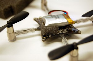
From our test in a calm pressure stable room the altitude is held at roughly ±15cm. However we had some problems when we where moving around. The Crazyflie sometimes suddenly rose and went to the ceiling. After some debugging we found that the problem was mainly physical, the pressure sensor is exposed of dynamic pressure when flying. To fix that we cut some of the foam we have in the Crazyflie box (yes that was planed all along ;-), and we stuck it on top of the pressure sensor. Doing so greatly improve the stability when flying more aggressively! (Something we kind of knew from peoples suggestions but it is nice to see it working in reality)
This functionality still require some debugging, tuning and code clean-up, but if you want to test it just grab the latest version of the firmware and client from Bitbucket. To begin with check that the altitude hold function is well configured for you joystick mapping (we found that it is best set on the shoulder button of the thrust hand). The altitude lock will be activated as long as the button is pressed. It can be pressed while the copter is flying or while it is in the ground. If pressed when the copter is in the ground, you will have to press the thrust joystick up a bit to make the copter fly higher. We also recommend to be a bit experienced with flying the Crazyflie as the altitude hold sometimes requires a quick recovery manoeuvre ;-).


