It seems that many of you are very interested in simulation. We might have gotten the hint when we noticed that our July’s development meeting had our best attendance so far! Therefore, we will be planning a new developer meeting to discuss the upcoming plans for supporting simulation for the Crazyflie.

Getting Started with Simulation tutorial
Perhaps you are not aware, but there is actually a Getting Started tutorial for simulation that has been available for a little over 2 months now. Unfortunately, circumstances prevented us from writing a blog post about it, but we’ve noticed that not all of you are aware of it yet!
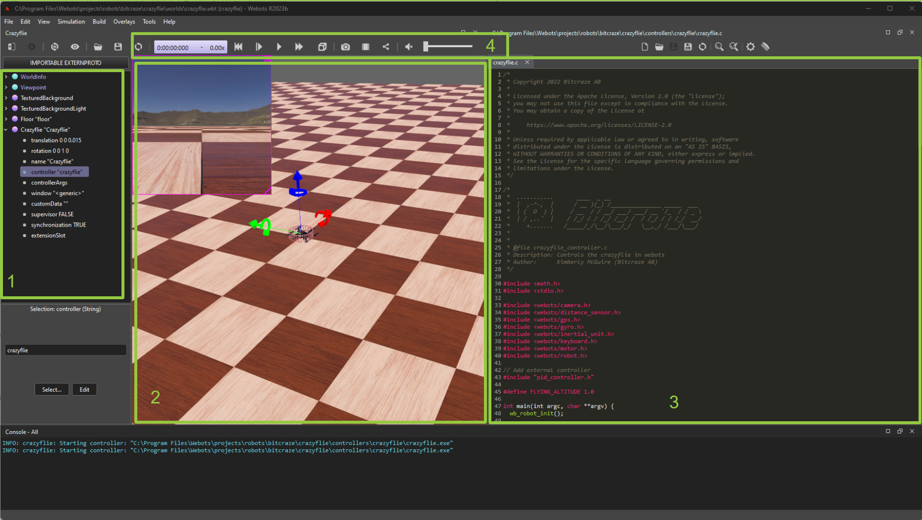
The getting-started tutorial demonstrates how to set up the Webots simulator, which already includes Crazyflie models and some cool examples:
- An example that you can control the Crazyflie with the keyboard
- An example that the Crazyflie does wall following autonomously
The latter is based on the example app layer for wall-following in the crazyflie-firmware repository. Starting this year, there’s also a Python library equivalent available.
The tutorial concludes with instructions on how to edit these controllers. Alternatively, you can choose to run the files directly from the crazyflie-simulation repository. After completing the tutorial, you can explore the simulation repository documentation for more information and to access additional examples.
Upcoming plans
With so many plans and so little time! This is a common phrase at Bitcraze, and it’s a symptom of being an overly ambitious, but too small, team. By the way, we are still looking for more people :). Nonetheless, we have big plans to take our Crazyflie simulation to the next level:
- ROS 2 Crazyflie model for Webots: The Crazyflie has been a part of the Webots standard robots for 2 years now, but we still need to implement the Crazyflie into the Webots ROS 2 repository.
- Better (new) Gazebo support: Currently, we only have a very simple example for Gazebo, which is limited to motors with no control input. Working with the C++ API can be a bit challenging, so it might be worth considering the use of ROS 2 in the loop here. Let’s see what comes out of it.
- Integration into Crazyswarm2: Once the Webots ROS2 node has been released, integrating the Crazyflie simulation into Crazyswarm2 will become more straightforward.
- Improvement to the Python bindings: We’ve had Python bindings for controllers and the high-level commander for a while. Recently, we also added Python bindings for the estimator (currently for loco positioning only). However, there are still some issues to address with the Python bindings for the controllers due to timing issues with the simulators.
- Linking with our CFLIB: Currently, both Webots and the Crazyflie Python library use entirely different APIs. This means that these scripts are not compatible and you’ll need to be creative not to reuse new code. However, wouldn’t it be nice to use a python example from the python library with a
--simand that it would actually control the Crazyflie in the simulator instead?
Of course, there are probably more improvements that we haven’t thought of yet, but that’s why we have developer meetings!
Come and join us at the Developer meeting.
We will be hosting another developer meeting on November 1st at 15:00 Central European Time (accounting for the time-shift from summer to autumn). You can find details on how to join in the discussion thread here.
Just for your information, I (Kimberly) am the main driving force behind our simulation efforts. However, I’m currently on partial sick leave and will soon be on full leave for a while. I kindly ask for your patience with the pace of ongoing developments. Remember, it’s an open-source project, so if you’d like to contribute and help out, we would greatly appreciate it :)