As mentioned in a previous blog post, we have a both at ICRA in London this week. If you are there too, come and visit us in booth H10 and tell us what you are working on!
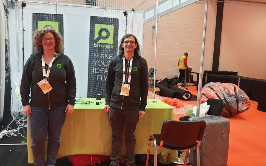
Barbara and Arnaud is getting the booth ready
We are showing our live autonomous demo and our products in the booth, including the flapping drone Flapper Nimble, don’t miss it!
The autonomous demo
The decentralized autonomous demo that we are showing is based on technologies in the Crazyflie ecosystem. The general outline is that Crazyflies are autonomously flying in randomized patterns without colliding. The main features are:
Positioning using the Lighthouse positioning system, all positioning estimation is done in the drone. The Lighthouse positioning system provides high accuracy and ease of use.
Communication is all peer-to-peer, no centralized functionality. Each Crazyflie is transmitting information about its state and position to the other peers, to enable them to act properly.
Collision avoidance using the on-board system without central planing. Based on the position of the other peers, each Crazyflie avoids collisions by modifying its current trajectory.
Wireless charging using the Qi-deck. When running out of battery, the Crazyflies go back to their charging pads for an automatic re-fill.
The App framework is used to implement the demo. The app framework provides an easy way of writing and maintaining user code that runs in the Crazyflie.
We are happy to answer any questions on how the technology works and implementation details. You can also read more about the demo in the original blog post by Marios.
Developer meeting
The next developer meeting is next week, Wed June 7 15:00 CEST and the topic will be the demo and how it is implemented. If you want to know about any specific technologies we used, how it is implemented or if you are just curious about the demo in general, please join the developer meeting. We will start with a presentation of the different parts of the demo, and after that a Q&A. As always we will end up with a section where you can ask any question you like related to our ecosystem. Checkout this announcement on our discussion platform for information on how to join.
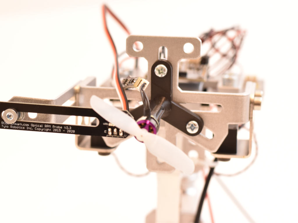
When designing flying robots like drones it is important to be able to benchmark and test the propulsion system which in this case is a speed controller, motor and propeller. As we at Bitcraze are mainly working with tiny drones we need a thrust stand designed for small motors and propellers. We have actually already designed our own system identification deck, which can measure overall efficiency, thrust, etc., but is lacking the ability to measure torque. Torque is needed to be able to measure propeller efficiency which is now something we would like to measure. Before we developed the system-id deck we searched for of the shelf solutions that could satisfy our needs and could not find any. This still seems true, please let us know if that isn’t the case.
Expanding the system-id deck to measure torque doesn’t work and building something from scratch was a too big of a project for us. Next natural option would then be to modify an existing thrust stand and our choice fell for the tyro robotics 158X series.
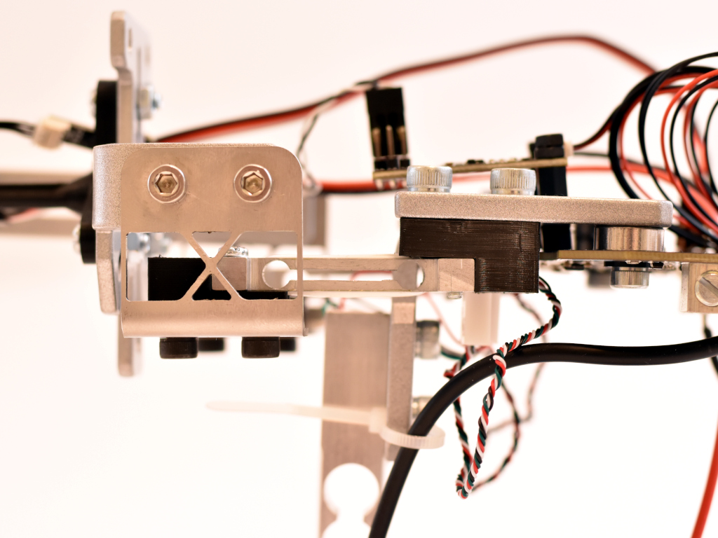
Looking at specifications, images and code we could figure out that replacing the load cells for more sensitive ones should be possible. The stock setup of 5kgf thrust and 2Nm of torque is just too much as we are looking for around 100 grams of thrust and around 10 mNm of torque. So we decided to give the replacement of load cells a shot! Assembly was quite smooth but we managed to break one of the surface mount load cell connectors off, luckily this was easily fixable with a soldering iron. With the stock setup we did some measurements with a 0802 11000KV brushless motor and a 55mm propeller in a pushing setup. It works but the measurements are noisy and repeatability is not great. Next thing would be to replace the load cells. The 158X uses TAL221 sized load cells which are available down to 1kg. We got those and with a calibration-allways-pass code we got from Tyto robotics we could make the calibration pass (note that modifying the thrust stand breaks the warranty). Now the thrust stability was much better but still the torque was a bit to noisy. We decided to go for even smaller thrust cells, the TAL220, and build 3D printable adapters to make them fit.
Now the torque noise level looked much better and so did the repeatability. By empirically measuring the thrust and torque using calibrated weights and by checking the measurements in RCBenchmark we got these values:
Thrust, calibrated weight [g]
Measured [g]
Noise [g]
200
200
1
100
100
1
50
50
0.5
20
20
0.5
10
10
0.5
0
0
0.5
Trust (calibrated using 200g weight)
Torque, calibrated weight [g]
Measured [mNm]
Noise [mNm]
200
257
2
100
128
1
50
64
0.3
20
25.7
0.3
10
12.7
0.3
0
0
0.2
Torque (calibrated using 200g weight)
Simple repeatability test
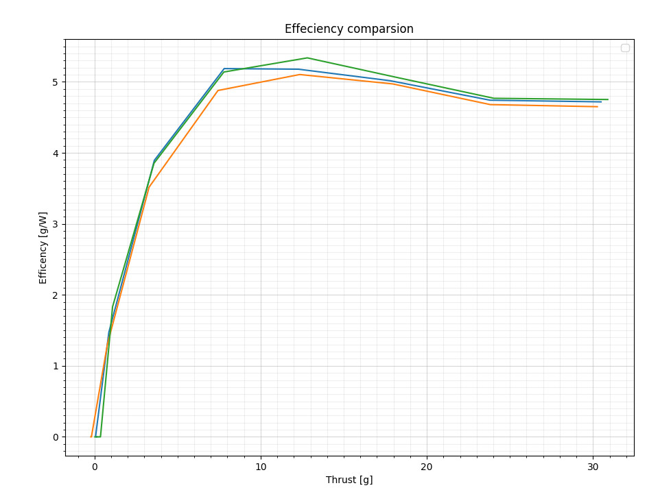
The thrust stand modification is still very fresh and we have to figure out some things but it all looks promising. For example we get 13% less overall efficiency when measuring it using our system-id thrust stand. Our guess is that it is due to that the Crazyflie arms in the system-id case blocks the airflow.
If you would like to do this modification yourself there are some simple instructions and STL files over at out mechanical github repository. Have fun!
It is easy to forget that the reason why it is nice to develop for the Crazyflie is because it weighs only about 30 grams. In case something goes wrong with your script or there is a fly-away, you can simply pick it up from the air without worrying about the propellers hitting you. Moreover, when the Crazyflie crashes, it usually only requires a brush off and a potential replacement of a motor-mount or propeller. The risk of damage to yourself, other people, indoor furniture, or the vehicle itself is extremely low. However, things become very different if you’ve built a larger platform with the Bolt or BQ deck with large brushless motors (like with this blogpost), where the risk of injury to people or to the vehicle itself increases significantly. That is one of the major reasons why the BQ deck and the Bolt are still in early access and have been for a while. In our efforts to get it out of early access, it’s time to start thinking about safety features.
In this blog post, we’ll be discussing how other open-source autopilot programs are implementing safety features, followed by a discussion on current efforts for Crazyflie, along with an announcement of the developer meeting scheduled for May 3rd (see below for more info).
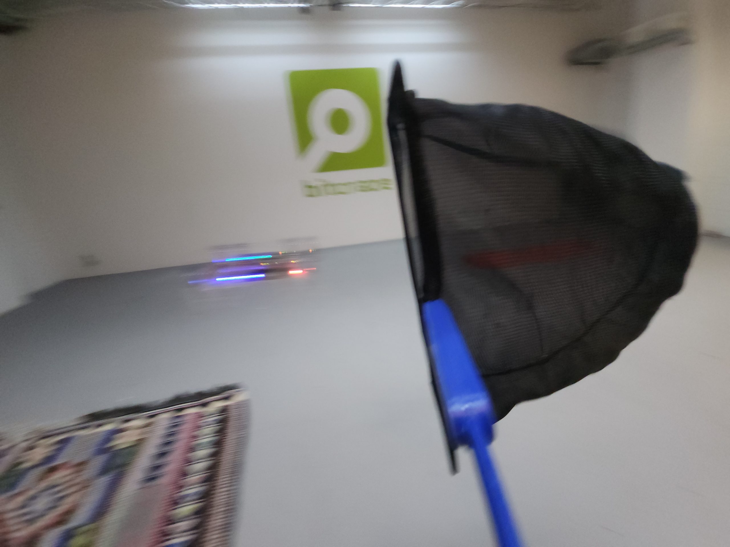
Catching the Crazyflie with a net
Safety in other Autopilots
We are a bit late to the game in terms of safety compared to other autopilot programs such as PX4, ArduPilot, Betaflight and Paparazzi UAV, which have been thinking about safety for quite some time. It makes a lot of sense when you consider the types of platforms that run these autopilots, such as large fixed VTOL or fixed-wing vehicles or 10-kilo quadcopters with cinematic cameras, or the degree of outdoor flight regulation. Flying a UAV autonomously or by yourself has become much more challenging as the US, EU, and many other countries have made it more restrictive. In most cases, you are not even allowed to fly if fail-safes are not implemented, such as what to do if your vehicle loses GPS signal. These types of measures can be separated into pre-flight checks and during-flight checks.
Pre-flight checks
Before a vehicle is allowed to fly, or even before the motors are allowed to spin, which is called ‘arming’, several conditions must be met. First, it needs to be checked if all internal sensors, such as the IMU, barometer, and magnetometer, are calibrated and functional, so they don’t give values outside of their normal operating range. Then, the vehicle must receive a GPS signal, and the internal state estimator (usually an extended Kalman filter) should converge to a position based on that information. It should also be determined if an external remote control is connecting to the vehicle and if there is any datalink to a ground station for telemetry. Feasibility checks can also be implemented, such as ensuring that the mission loaded to the UAV is not outside its mission parameters or that the start location is not too far away from its take-off position (assuming the EKF is functional). Additionally, the battery should not be low, and the vehicle should not still be in an error state from a previous flight or crash.
All of these features have the potential to be turned off or made less restrictive, depending on your situation. However, keep in mind that changing any of these may require recertification of the drone or make it fall outside what is required for outdoor flight regulation. Therefore, these should only be changed if you know what you are doing.
Now that the pre-flight checks have passed, the UAV is armed and you have given it the takeoff command. However, there is so much more that can go wrong during a UAV flight, and takeoff is one of the most dangerous moments where everything could go wrong. Therefore, there are many more safety features, aka failsafes, during the flight than for the pre-flight checks. These can also be separated into ‘triggers’ and ‘behaviors,’ so that the developer can choose what the UAV should do in case of a failure, such as ‘GPS loss’ to ‘land safely’ and so on.
Thus, there are triggers that can enable the autopilot’s failsafe mechanics:
No connection with the remote control
No connection with the Ground station or Datalink
Low Battery
Position estimate diverges or full GPS loss
Waypoint going beyond geofence or Mission is not feasible
Other vehicles are nearby.
Also, sometimes the support of an external Automatic Trigger system is required, which is a box that monitors the conditions where the UAV should take action in case there is no GPS, other aerial vehicles are nearby, or the UAV is crossing a geofence determined by outdoor flight restrictions. Note that all of these triggers usually have a couple of conditions attached, such as the level of the ‘low battery’ or the number of seconds of ‘GPS loss’ deemed acceptable.
Fail-safe behavior
If any of the conditions mentioned above are triggered, most autopilot suites have some failsafe behaviors linked to those set by default. These behaviors can include the following:
No action at all
Warning on the console or remote control display
Continue the mission autonomously
Stay still at the same position or go to a home position
Fly to a lower altitude
Land based on position or safely land by reducing thrust
No input to motors or completely disarming the motors
Usually, these actions are set in regulation, but per trigger, it is possible to give a different behavior than the default. One can decide to completely disarm the vehicle, but then the chances of the UAV crashing are pretty high, which can result in damage to the vehicle or cause harm to people or objects. By the way: disarming is the opposite act of arming, which is not allowing the motors to spin, no matter if it is receiving an input. If you decide to never do anything and force the drone to finish the mission autonomously, then in a case of GPS or position loss, you risk losing your vehicle or that it will end up in areas where it is absolutely not allowed, such as airports. Again, changing these default behaviors should be done by someone who knows what they are doing, and it should be done with careful consideration.
Fail-safes are measures that ensure safe flight. However, there will always be a chance that an emergency will occur, which will require an immediate action as well. If the vehicle has crashed during any of its phases or has flipped, or if the hardware breaks, such as the motors, arms, or perhaps even the autopilot board itself, what should be done then?
The standard default behavior for this is to completely disarm the vehicle so that it won’t react to any input to the motors itself. Of course, it’s difficult to do if the autopilot program is on, but at least it won’t try to take off and finish its mission while laying on its side. It might be that a backup system is connected to the ESCs that will take over in case the autopilot is not responding anymore, perhaps using a different channel of communication.
Also, the most important safety feature of all is the pilot itself. Each remote control should have a special button or switch that can put the drone in a different mode, make it land, or disarm it so that the pilot can act upon what they see. In case the motors are still spinning, have a net or towel available to throw over them, disconnect the battery as soon as possible, and make sure to have sand or a special fire retardant in case the LiPo batteries are pierced.
All of the autopilots have some tips to deal with such situations, but make sure to do some good research yourself on how to handle spinning parts or potential LiPo battery fires. I’m just giving a compilation of tips given in the documentation above here, but please make sure to read up in detail!
Safety in the Crazyflie Firmware
So how about the Crazyflie-firmware ? We have some safety features build in here and there but it is all over the code base. Since the Crazyflie is so safe, there was no immediate need for this and we felt it is more up to the developer to integrate it themselves. But with the Bolt and BQ deck coming out of early access, we want to at least do something. As we started already started looking into how other autopilot softwares are doing it, we can get some ideas, however we did notice that many of these are mostly meant for outdoor flight. The Crazyflie and the Crazyflie Bolt have been designed for indoor use and perhaps deal with different issues as well.
Current safety features
This is a collection of safety features currently in the firmware at the time of writing this blogpost. Most safety features in the Crazyflie are up for the developer to double check before and during flight, but these are some automatic once that are scattered around the firmware:
Watchdog, hard faults and asserts scattered throughout the firmware.
We might find more on the way…
However, if for instance your Crazyflie or Bolt platform loses its positioning in air, or doesn’t have a flowdeck attached before takeoff, there are no default safety systems in check. You either need to catch it, make it land or use an self-made emergency stop button using one of the emergency stop services above.
Safety features in works
As mentioned earlier, we have safety features spread throughout the code base of the Crazyflie firmware. Our current effort is to collect all of these emergency stops and triggers in the supervisor module to have them all in one place.
In addition, since indoor positioning is critical, we want to be notified when it fails. For instance, if the lighthouse geometry is incorrect, we need to see if the position diverges. This check was done outside of the Crazyflie firmware in a cflib script, but it has not been implemented inside the firmware. We also want to provide some options in terms of behavior for these triggers. Currently, we are working on two options: ‘turn the motors off’ or ‘safe land,’ with ‘safe land’ decreasing the thrust while keeping the drone level in attitude.
Furthermore, we want to integrate these features into the cfclient as well. For example, we want to add more emergency safety features to our remote control through the cfclient, and show users how to arm and disarm the vehicle.
These are the elements we are currently working on, but there might be more to come!
Developer meeting May 3rd
You probably already guessed it… the topic about the next developer meeting will be about the safety features in the Crazyflie and the Bolt! We will present the current safety features in the Crazyflie and what we are currently working on to make it better. In this sense, we really want to have your feedback on what you think is important for brushless versions of the Crazyflie for indoor flight!
The Dev meeting will be on Wednesday May the 3rd at 3 PM CEST. Please keep an eye on the discussion forum in the developer meeting thread.
Today, our guest Airi Lampinen from Stockholm University is presenting the second Drone Arena Challenge. Enjoy!
Welcome to the second Drone Arena Challenge, a one-of-a-kind interactive experience with Bitcraze’s Crazyflie! This year, the challenge is focused on moving together with drones in beautiful, curious, and provocative ways – without needing to write a single line of code!
Moving with drones. Image credit: Rachael Garrett.
What, when, where? The event takes place May 16-17, 2023 at KTH’s Reactor Hall in Stockholm – a dismantled nuclear reactor hall – which provides a unique setting for creative human–drone encounters. You don’t need your own drone or be able to program a drone to participate! We will provide the drone equipment (a Crazyflie 2.1 equipped with the AI-deck) and take care of everything necessary to make them fly. What you need to do is to be creative and move together with the drones to set up the best show you can deliver! There’ll be a jury judging the final performances and we have exciting prizes for the most successful teams!
Drone Arena in the Reactor Hall. Picture from the first challenge, held in June 2022. Picture credit: Fatemeh Bakhshoudeh
Who can join? Anyone irrespective of training, profession, and past experience with drones or performing arts is welcome to participate. Participants need to be at least 18 years old. If you are curious about how technology and humans may play together, enthusiastic about the Crazyflie, or eager to learn how to move with the Crazyflie, this event is for you. We welcome up to 10 pairs (teams of 2 people) to participate in the challenge.
Registration is already open, with only a few spots remaining. We encourage those interested to sign up as soon as possible to secure their spot!
Program & prizes? On the first day of the hackathon, we will host a keynote speaker and a short information session to explain what participants are expected to do and what support is available for them. The teams will then have access to the Reactor Hall to work on the challenge and explore moving with their drone – we offer long hours but each team is free to choose how much they want to work. (The goal here is to have a good time!) The competition itself takes place on the second day. We’ve got exciting prizes for the most successful teams!
In this blog post we will take a look at the new Loco positioning TDoA outlier filter, but first a couple of announcements.
Announcements
Crazyradio PA out of stock
Some of you may have noticed that there are a lot bundles out of stock in our store, the reason is the transition from Crazyradio PA to the new Crazyradio 2.0. Most bundles contain a radio and even though the production of the new Crazyradio 2.0 is in progress, the demand for the old Crazyradio PA was a bit higher than anticipated and we ran out too early. Sorry about that! We don’t have a final delivery date for the Crazyradio 2.0 yet, but our best guess at this time is that it will be available in about 4 weeks.
Developer meeting
The next developer meeting is on Wednesday, April 5 15:00 CEST, the topic will be the Loco positioning system. We’ll start out with around 30 minutes about the Loco Positioning system, split into a presentation and Q&A. If you have any specific Loco topics/questions you want us to talk about in the presentation, please let us know in the discussions link above.
The second 30 minutes of the meeting with be for general support questions (not only the Loco system).
The outlier filter
When we did The Big Loco Test Show in December, we found some issues with the TDoA outlier filter and had to do a bit of emergency fixing to get the show off the ground. We have now analyzed the data and implemented a new outlier filter which we will try to describe in the following sections.
Why outlier rejection
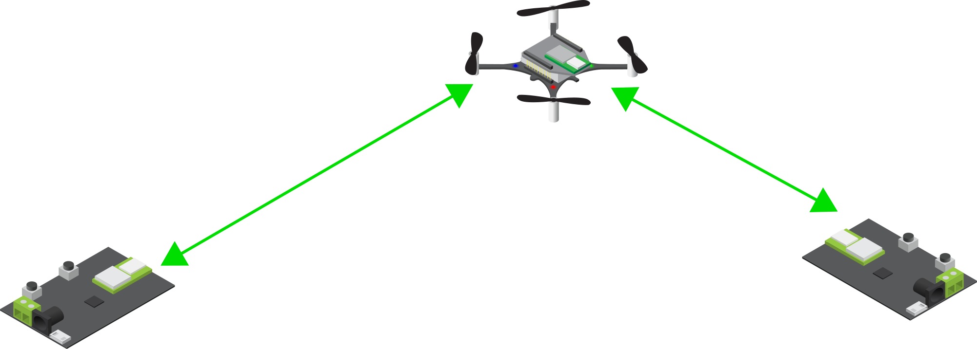
In the Loco System, there are a fair amount of packets that are corrupt in one way or the other, and that should not be part of the position estimation process. There are a number of reasons for errors, including packet collisions, interference from other radio systems, reflections, obstacles and more. There are several levels of protection in the path from when an Ultra Wide Band packet is received in the Loco Deck radio to the state estimator, that aims at removing bad packets. It works in many cases, but a few bad measurements still get all the way through to the estimator, and the TDoA outlier filter is the last protection. The result of an outlier getting all the way through to the estimator is usually a “jump” in the estimated position, and in worst case a flip or crash. Obviously we want to catch as many outliers as possible to get a good and reliable position estimate and smooth flight.
The problem(s)
The general problem of outlier rejection is to decide what is a “good” measurement and what is an outlier. The good data is passed on to the state estimator to be used for estimating the current position, while the outliers are discarded. To decide if a measurement is good or an outlier, it can be compared to the current position, if it is “too far away” it is probably an outlier and is rejected. The major complication is that the only knowledge we have about the current position is the estimated position from the state estimator. If we let outliers through, the estimated position will be distorted and we may reject good data in the future. On the other hand if we are too restrictive, we may discard “good” measurements which can lead to the estimator loosing tracking and the estimated position drift away (due to noise in other sensors). It is a fine balance as we use the estimated position to determine the quality of a measurement, at the same time as the output of the filter affects the estimated position.
Another group of parameters to take into account is related to the system the Crazyflie and Loco deck are used in. The over all packet rate in a TDoA3 system is changed dynamically by the anchors, the Crazyflie may be located in a place where some anchors are hidden, or the system may use the Long Range mode that uses a lower packet rate. All these factors change the packet rate and his means that the outlier filter should not make assumptions about the system packet rate. Other factors that depend on the system is the physical layout and size, as well as the noise level in the measurements, and this must be handled by the outlier filter.
In a TDoA system, the packet rate is around 400 packets/s which also puts a requirement on resource usage. Each packet will be examined by the outlier filter, why it should be fairly light weight when it comes to computations.
Finally there are also some extra requirements, apart from stable tracking, that are “nice to have”. As a user you probably expect the Crazyflie to find its position if you put it somewhere on the ground, without having to tell the system the approximate position, that is a basic discovery functionality. Similarly if the system looses position tracking, you might expect it to recover as soon as possible, making it more robust.
The solution
The new TDoA outlier filter is implemented in outlierFilterTdoa.c. It is only around 100 lines of code, so it is not that complex. The general idea is that the filter can open and close dynamically, when open all measurements are passed on to the estimator to let it find the position and converge. Later, when the position has stabilized, the filter closes down and only lets “good” measurements through. In theory this level of functionality should be be enough, after the estimator has converged it should never lose tracking as long as it is fed good data. The real world is more complex, and there is also a feature that can open the filter up again if it looks like the estimator is diverging.
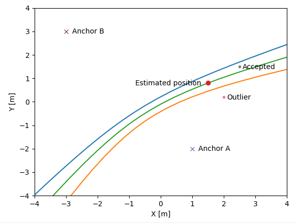
The first test in the filter is to check that the TDoA value (the measurement) is smaller than the distance between the two anchors involved in the measurement. Remember that the measurements we get in a TDoA system is the difference in distance to two anchors, not the actual distance. A measurement that is larger than the distance between the anchors is not physically possible and we can be sure that the measurement is bad and it is discarded.
The second stage is to examine the error, where the error is defined as the difference between the measured TDoA value and the TDoA value at our estimated position.
float error = measurement - predicted;
This error does not really tell us how far away from the estimated position the measurement is, but it turns out to be good enough. The error is compared to an accepted distance, and is considered good if it is smaller than the accepted distance.
sampleIsGood = (fabsf(error) < acceptedDistance);
The area between the blue and orange lines represents the positions where the error is smaller than some fixed value.
The rest of the code is related to opening and closing the filter. This mechanism is based on an integrator where the time since the last received measurement is added when the error is smaller than a certain level (integratorTriggerDistance), and remove if larger. If the value of the integrator is large, the filter closes, and if it is smaller than a threshold it opens up. This mechanism implements a hysteresis that is independent on the received packet rate.
The acceptedDistance and integratorTriggerDistance are based on the standard deviation of the measurement that is used by the kalman estimator. The idea is that they are based on the noise level of the measurements.
Feedback
The filter has been tested in our flight lab and on data recorded during The Big Loco Test Show. The real world is complex though and it is hard for us to predict the behavior in situations we have note seen. Please let us know if you run into any problems!
The new outlier filter was pushed after the 2023.02 release and is currently only available on the master branch in github (by default). You have to compile from source if you want to try it out. If no alarming problems surface, it will be the the default filter in the next release.
We are excited to announce that we will be having developer meetings on first Wednesdays of every month! Additionally, we are thrilled to be present in person at ICRA 2023 in London. During the same conference, there will be half day workshop called ‘The Role of Robotics Simulators for Unmanned Aerial Vehicles’ so make sure to sign-up! Please check out our newly updated event-page !
Monthly Developer meetings
We have had some online developer meetings in the past covering various topics. While these meetings may not have been the most popular, we believe it is crucial to maintain communication with the community and have interesting discussions, and exchange of ideas. However, we used to plan them ad-hoc and we had no regularity in them, which sometimes caused some of us **cough** especially me **cough**, to create confusion about the timing and location. To remove these factors of templexia (dyslexia for time), we will just have it simply on the first Wednesday of every month.
So our first one with be on Wednesday 5th of April at 15:00 CEST and the information about the particular developer meeting will be as usual on discussions. From 15:00 – 15:30 it will be a general discussion, probably with a short presentation, about a topic to be determined. From 15:30-16:00 will address regular support question from anybody that need help with their work on the Crazyflie.
ICRA 2023 London
ICRA will be held in London this year, from May 29 – June 2nd, atthe ExCel venue. We will be located in the H11 booth in the exhibitor hall, but as the date approaches, we will share more about what awesome prototypes we will showcase and what we will demonstrate on-site. Rest assured, plenty of Crazyflies will be flown in the cage! To get an idea of what we demo-ed last year it IROS Kyoto, please check out the IROS 2022 event page. Matej from Flapper Drones will join us at our booth to showcase the Flapper drone.
We are thinking of organizing a meetup for participants on the Wednesday after the Conference Dinner, so we will share the details of that in the near future as well. Also keep an eye on our ICRA 2023 event page for updated information.
Additionally, participants can submit an extended abstract to be invited for an poster presentation during the same workshop. The submission deadline has been extended to April 3rd, so for more information about submission, schedule and speaker info, go to the workshop’s website.
This week’s guest blogpost is from Florian Goralsky from Bok o Bok about their dance piece with multiple Crazyflies. Enjoy!
Flying bodies across the fields is a contemporary dance piece for four performers and a swarm of drones, exploring the phenomenon of the disappearance of bees and the use of pollinating drones to compensate for this loss. The piece attempts to answer this crucial question in a poetical way: can the machine create life and save us from ecological disaster?
We’re super excited to talk about a performance that we’ve been working on for the past two years in collaboration with Bitcraze. It premiered at the Environmental Forum, Centre Pompidou Paris, in 2021, and we’ve had the opportunity to showcase it at different venues since then. We are happy to share our thoughts about it!
Choreographic research
Beyond symbolizing current attempts to use drones to pollinate fields, the presence of the Crazyflie drones, supports the back and forth between nature and technology. We integrate a swarm, performing complex choreographies, which refer to the functioning of a beehive, including the famous “bee dance”, discovered by Karl von Frisch, which is used to transmit information on the food sources. Far from having a spectacular performance as its only goal, the synchronization of autonomous drones highlights bio-inspired computer techniques, focused on collective intelligence.
Making a dance performance with drones needs a high accuracy and adaptability, both before and during the show. Usually, we only have a few hours, sometimes even a few minutes, to setup the system according to the space. We quickly realized we needed pre-recorded choreographies, and hybrid choreographies where the pilot could have a few degrees of freedom on pre-defined behaviors.
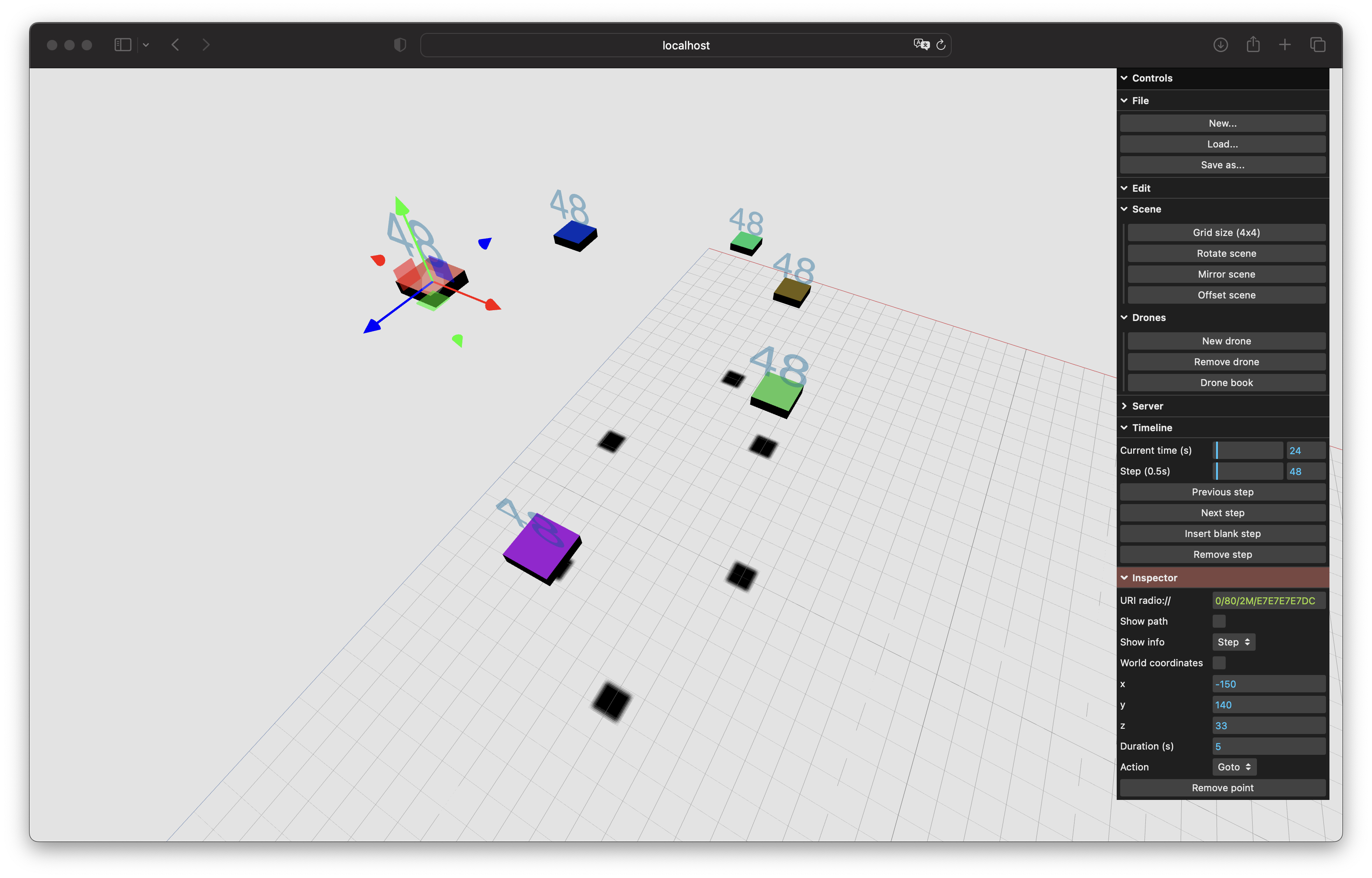
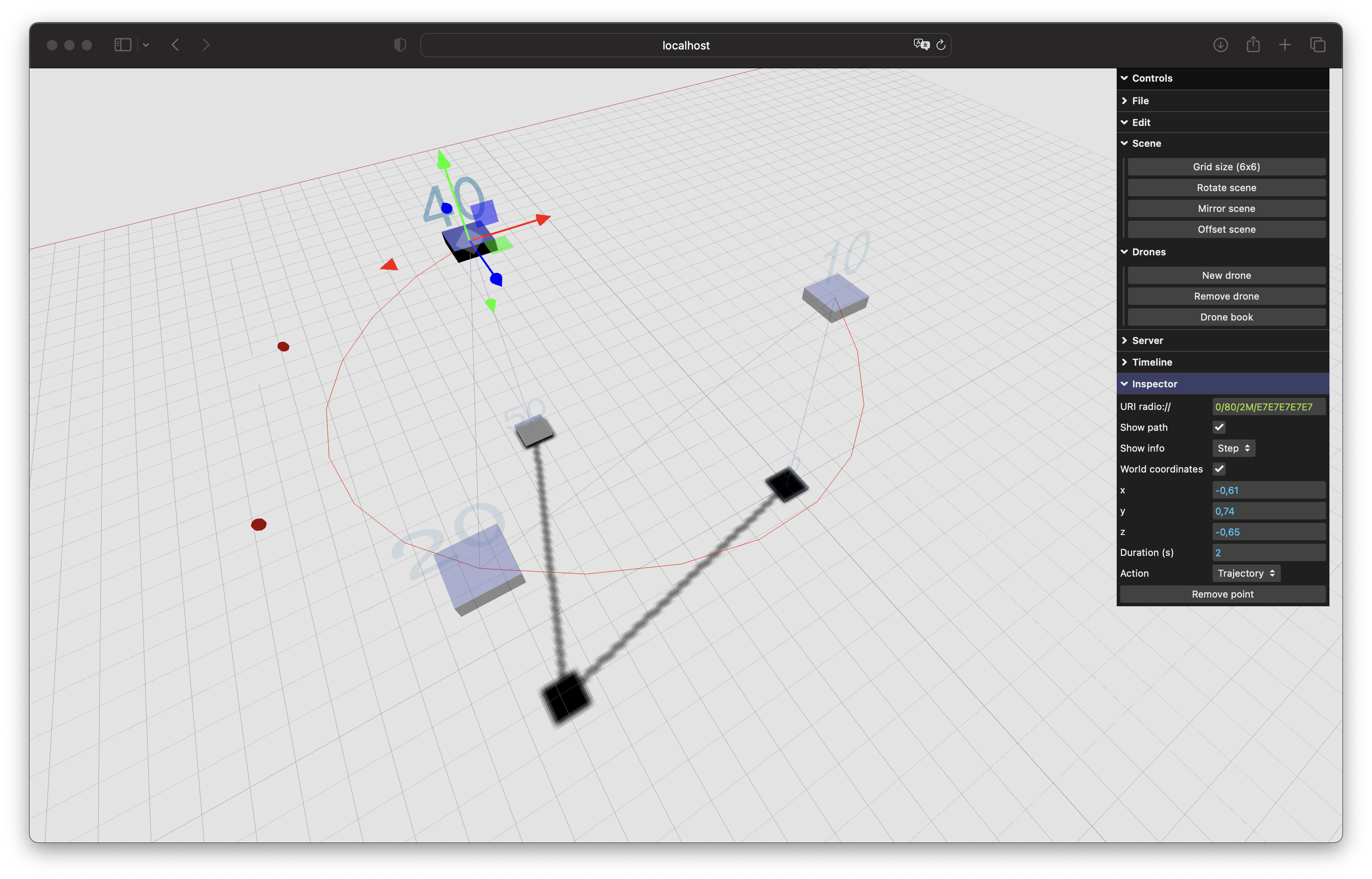
GUI Editor + Python Server
Taking this into account, we developed a web GUI editor, that is able to send choreographies created with any device to a Websocket Python server. The system supports any absolute positioning system (We use the Lighthouse), and then converts all the setpoints and actions to the Crazyflie API HighLevelCommander class. This system allows us to create, update, and test complex choreographies in a few minutes on various devices.
Preview position of six drones at a certain time.Early support of the CompressedTrajectories format, with Cubic bezier curves.
What is next?
We are looking forward to developing more dancers-drones interactions in the future. It will imply, in addition to the Lighthouse system, other sensors, in order to open up new possibilities: realtime path-finding, obstacle avoidance even during a recorded choreography (to allow improvisation), etc.
We’re happy to announce that the 2023.02 release is available for download!
The main new features of this release are:
Out of tree controllers
We have made it easier to add a new controller to the firmware in the Crazyflie. Controllers can now be added in an app, the same way as an estimator can be added. The main advantage is that all the code is contained in the app which makes it easy to upgrade the underlying firmware when new releases are available. You can read about how to use this feature in the firmware repository documentation.
Support to configure ESCs with BLHeli Configurator
On brushless Crazyflies, ESCs can now be configured using the BLHeli Configurator. See PR #1170
A UKF (Unscented Kalman Filter) state estimator has been added
An Unscented Kalman Filter (UKF) estimator has been added based by Klaus Kefferpütz from the paper ‘Error-State Unscented Kalman-Filter for UAV Indoor Navigation‘. The estimator is still slightly experimental and does not yet support all positioning methods (see this issue). Because of this, it is not available by default, but you can try it by enabling it using kbuild! You can read about the UKF estimator in the repository documentation.
Platform filter in client flash dialog
A filter has been added to the bootloader dialog in the client to make it easier to find the correct release. Releases are now filtered based on platform to avoid the clutter of mixing releases for cf2, tag, bolt and flapper.
Stability and bug fixes
We have fixed several bugs in the firmware and client software that, but you can check the release notes for each of these for further details.
We have created a simple deprecation policy to clarify future changes of the APIs. The short version is that we from now on will mention deprecated functionality in release notes and that the deprecated functionality will remain in the code base for 6 months before it is removed. Please see the development overview for more information.
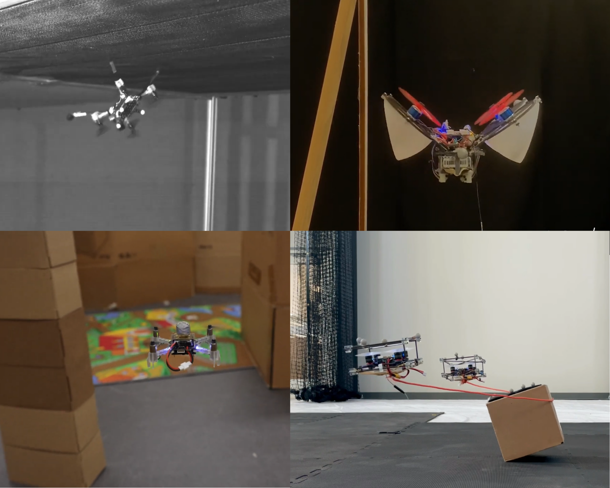
It’s time for a new compilation video about how the Crazyflie is used in research ! The last one featured already a lot of awesome work, but a lot happened since then, both in research and at Bitcraze.
As usual, the hardest about making those videos is choosing the works we want to feature – if every cool video of the Crazyflie was in there, it would last for hours! So it’s just a selection of the most videogenic projects we’ve seen. You can find a more extensive list of our products used in research here.
We’ve seen a lot of projects that used the modularity of the Crazyflie to create awesome new features, like a catenary robot, some wall tracking or having it land upside down. The Crazyflie board was even made into a revolving wing drone. New sensors were used, to sniff out gas leaks (the Sniffy bug as seen in this blogpost), or to allow autonomous navigation. Swarms are also a research topic where we see a lot of the Crazyflie, this time for collision avoidance, or path planning. We also see more and more of simulators, which are used for huge swarms or physics tests.
Once again, we were surprised and awed by all the awesome things that the community did with the Crazyflie. Hopefully, this will inspire others to think of new things to do as well. We hope that we can continue with helping you to make your ideas fly, and don’t hesitate to share with us the awesome projects you’re working on!
Here is a list of all the research that has been included in the video:
A common task with the Crazyflie is to add a new controller or estimator. As we get some questions on how to do this, we will outline the process in this post. We will show how to add a custom controller and estimator that runs in the Crazyflie, built as an out-of-tree build.
This post assumes some basic knowledge about the Crazyflie firmware, the C programming language, how to build the firmware and flash it to a Crazyflie. If you need some more information on these topics, please see the “Getting started with development” tutorial. For an overview of how estimators and controllers are used by the stabilizer module, please see the firmware documentation.
Overview
The Crazyflie firmware is designed to make it easy to add custom controllers and estimators, a plugin system keeps the code clean and well separated. We will look at the details later, but the basic principle is to first write your new controller or estimator and then register it in the firmware. When the code has been compiled and flashed to the Crazyflie, the new module is activated by setting a parameter from the client or a python script.
We will implement the example as an app, which is a great way to make sure you can upgrade the underlying firmware without messing up your code. An app is a piece of code that exists somewhere in you file system outside of the main firmware source code. This setup minimizes the dependencies and the main firmware source tree can be upgraded without affecting your app (in most cases). That means there is no need for merges or complex management of source trees.
Registration of modules
Let’s first look at how controllers and estimators are registered and called in the plugin framework. We will use the controllers to show how it works, but the estimators are implemented in a similar way and it should be easy to understand how it works.
Note that there has been some updates of the Crazyflie firmware source code lately and any reference to the source code will be to the latest version (as of today).
The starting point of the controller implementation can be found in the src/modules/src/controller.c file, here we can find an array called controllerFunctions that holds a list of all the controllers in the system.
We can see that there is currently four controllers in the list: the PID controller, the Mellinger controller, the INDI controller and finally the Brescianini controller. There is also an “empty” controller at the top that is not important in this context and we will simply ignore it. At the bottom we find the out-of-tree controller, we will discuss this later.
Each controller must implement three functions: an initialization function, a test function and a controller function that performs the actual controller work. Signatures for the three functions are defined in controller.c. The functions are added to the list as function pointers that can be called by the stabilizer when needed.
There is a parameter, stabilizer.controller, in the stabilizer that tells the system which controller to use in the stabilizer loop. This parameter simply contains the index in the controllerFunctions list that will be used. For example, the default value 1 will make the stabilizer loop call the controllerPid function every iteration. If the value of the stabilizer.controller parameter is changed, the initialization function for the new controller will be called and subsequent calls from the stabilizer loop will be done to the new controller function.
We will not go into details of how to implement the actual controller here, but the existing controllers can be used as examples.
Suppose you want to add a new controller. It would be possible to add a new file in the Crazyflie firmware with your new controller implementation, add the function pointers to the list in controller.c and that would work just fine. The problem with such implementation would be that it is hard to maintain, your new files would be mixed with the files in the main firmware file tree, and even worse, you would have to modify the controller.c file to add your controller. The next time there is a new awesome feature in the firmware source code and you want to upgrade to the latest version, you will run into problems as you have to handle the files you modified!
A better solution is to use an app instead as apps are built out-of-tree, that is not in the main source tree. This removes the problem of merging changes in the main source files, all you have to do is to pull in the new file tree and recompile.
But how to register your new controller in the controller list? This is what the last line in the list of controllers is for
If CONFIG_CONTROLLER_OOT is defined we add a controller with the three functions controllerOutOfTreeInit, controllerOutOfTreeTest and controllerOutOfTree. All you have to do in your app is to define CONFIG_CONTROLLER_OOT and make sure the functions in your controller are named like above. That’s it!
Example implementation
Now we will create a new app and add a new controller, step by step. We assume that you have a newly cloned firmware repository in your filesystem to work on.
We will show the linux flavor of commands, but it should be easy to convert to other platforms.
Create a new app
The easiest way is to start from an existing app to get started, let’s use the hello world app. Copy the app and move into the new directory
cp -r examples/app_hello_world examples/my_controller
cd examples/my_controller/
Let’s rename hello_world.c
mv src/hello_world.c src/my_controller.c
We have to tell kbuild that we renamed the file. Open src/Kbuild in your favorite editor and update it to
obj-y += my_controller.o
Now let’s fix the basics in my_controller.c, open it in your editor and change according to the comments bellow:
#include <string.h>#include <stdint.h>#include <stdbool.h>#include "app.h"#include "FreeRTOS.h"#include "task.h"// Edit the debug name to get nice debug prints#define DEBUG_MODULE "MYCONTROLLER"#include "debug.h"// We still need an appMain() function, but we will not really use it. Just let it quietly sleep.
void appMain() {
DEBUG_PRINT("Waiting for activation ...\n");
while(1) {
vTaskDelay(M2T(2000));
// Remove the DEBUG_PRINT.// DEBUG_PRINT("Hello World!\n");
}
}Code language:PHP(php)
Now, lets add our new controller. We will not add a real implementation here as it would be a bit too large for this post, instead we will just call into the PID controller to make sure the Crazyflie still can fly. Add this code after appMain() in my_controller.c.
// The new controller goes here --------------------------------------------// Move the includes to the the top of the file if you want to#include "controller.h"// Call the PID controller in this example to make it possible to fly. When you implement you own controller, there is// no need to include the pid controller.#include "controller_pid.h"
void controllerOutOfTreeInit() {
// Initialize your controller data here...// Call the PID controller instead in this example to make it possible to fly
controllerPidInit();
}
bool controllerOutOfTreeTest() {
// Always return truereturntrue;
}
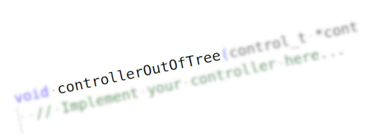
void controllerOutOfTree(control_t *control, const setpoint_t *setpoint, const sensorData_t *sensors, const state_t *state, const uint32_t tick) {
// Implement your controller here...// Call the PID controller instead in this example to make it possible to fly
controllerPid(control, setpoint, sensors, state, tick);
}
Code language:PHP(php)
Finally we need to tell the firmware that we have implemented the out-of-tree controller and that it should be added to the list. We do this by adding CONFIG_CONTROLLER_OOT to the app-config file. When you are done it should look like this:
Start your Crazyflie and the python client. Connect the client to the Crazyflie and open the console log tab. Make sure you are running your app by looking for the line:
MYCONTROLLER: Waiting for activation ...Code language:HTTP(http)
Now let’s activate our new controller! Open the parameter tab, find the stabilizer group and the controller parameter. Set it to 5 and check the console log that the out-of-tree controller was activated:
CONTROLLER: Using OutOfTree (5) controllerCode language:HTTP(http)
That’s it! Your new controller is activated and the Crazyflie is ready to fly.
Note: In the client, the comment for the stabilizer.controller parameter will not contain the out-of-tree controller, and it will look like only values 0-4 are valid even though 5 also works.
Conclusions
In this post we have shown how to add a new controller to the Crazyflie firmware. The process for adding an estimator is very similar, and hopefully it should be easy to understand how to do it based on the example above.
As you can see, very little code (apart from the actual controller/estimator) is required to add your own controller or estimator, and we hope that it will enable you to put your energy into the actual control problem, rather than the nitty gritty details of the code.