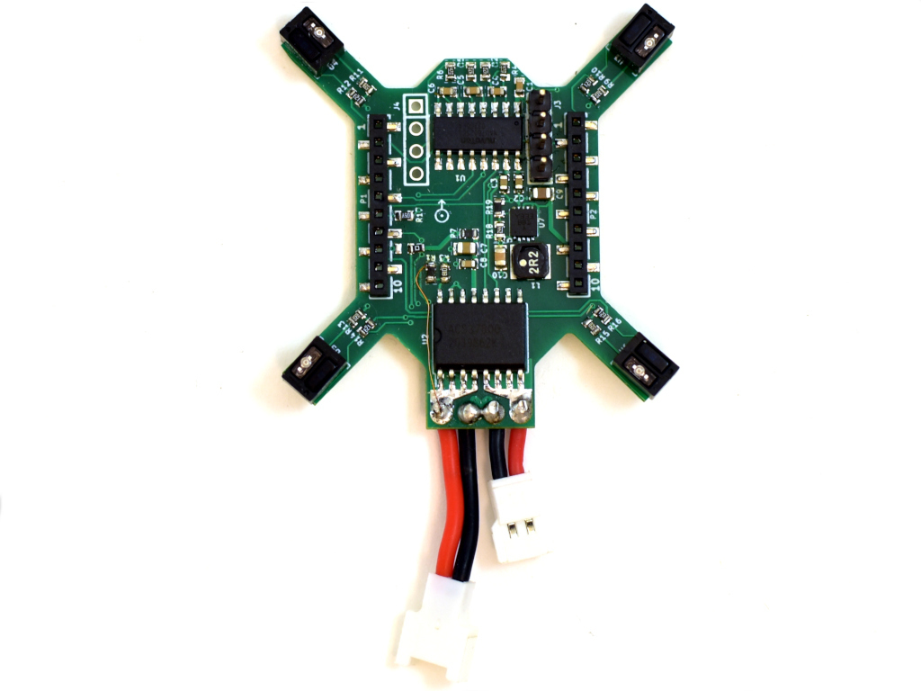
Previously we have been using off the shelf scales and other methods to measure characteristics, such as thrust or efficiency, of the Crazyflie products. We thought it was time to build something that is easier to use, more repeatable and tailored to our needs. Well, this has been on our wanted list for a long time, already back from when we did the RPM-deck. It was however first when Wolfgang visited us this winter that he nudged us over the edge so we finally allocated some time for it. We started off by buying some load cells and breakout boards to do something simple as a start, so we could at least measure thrust more easily. We actually started looking for off the shelf thrust stands but could not find anything suitable for the Crazyflie’s size. As is often the case here at Bitcraze, the project grew. Already before we had any load cells up and running I was designing a deck with RPM sensors, load cell amplifier and power meter. Now with the objective to easily do system identification. Therefor we named the deck the system-id deck.
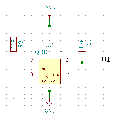
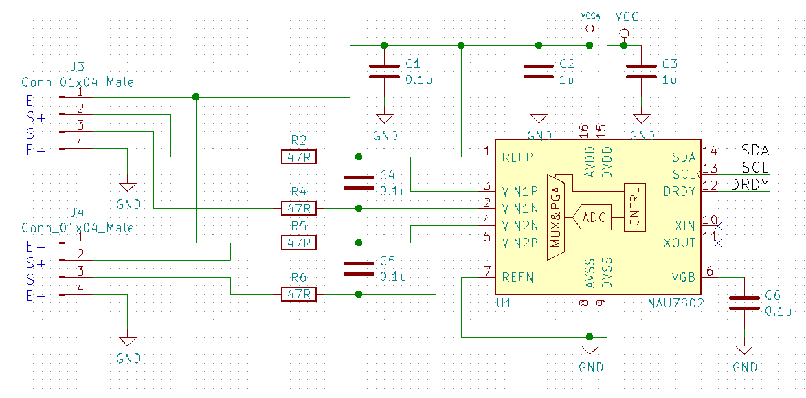
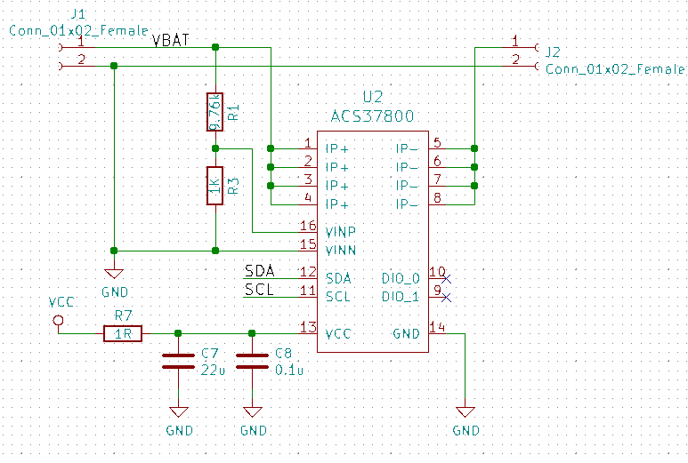
For the RPM sensors we used the same as on the RPM-deck, the QRD1114. They are not great as they need a reflective surface, this means adding white stickers or paint to black propellers, but they work well enough. The load cell amplifiers ended up to be the NAU7802 as it has a high accuracy and sample rate. For power metering we chose the new ACS37800 power monitoring IC that can handle up to 30A, this looked exiting.
The QRD1114 we wired the same way as previously done on the RPM-deck:
The NAU7802 was configured as per the datasheet suggestion and similarly to other open designs out there:
The ACS37800 was very new so the datasheet had to be used as the main information source. A bit tricky as this chip is mainly intended to measure mains supply, and we wanted to measure low voltage DC, which it said it could do…and in the end we managed to get it working.
We also added a buck/boost DC/DC that could provide a stable 3.3V from 2-5V input, just in case, as the ACS37800 is specified for this voltage and not the 3.0V the Crazyflie can supply.
The outcome
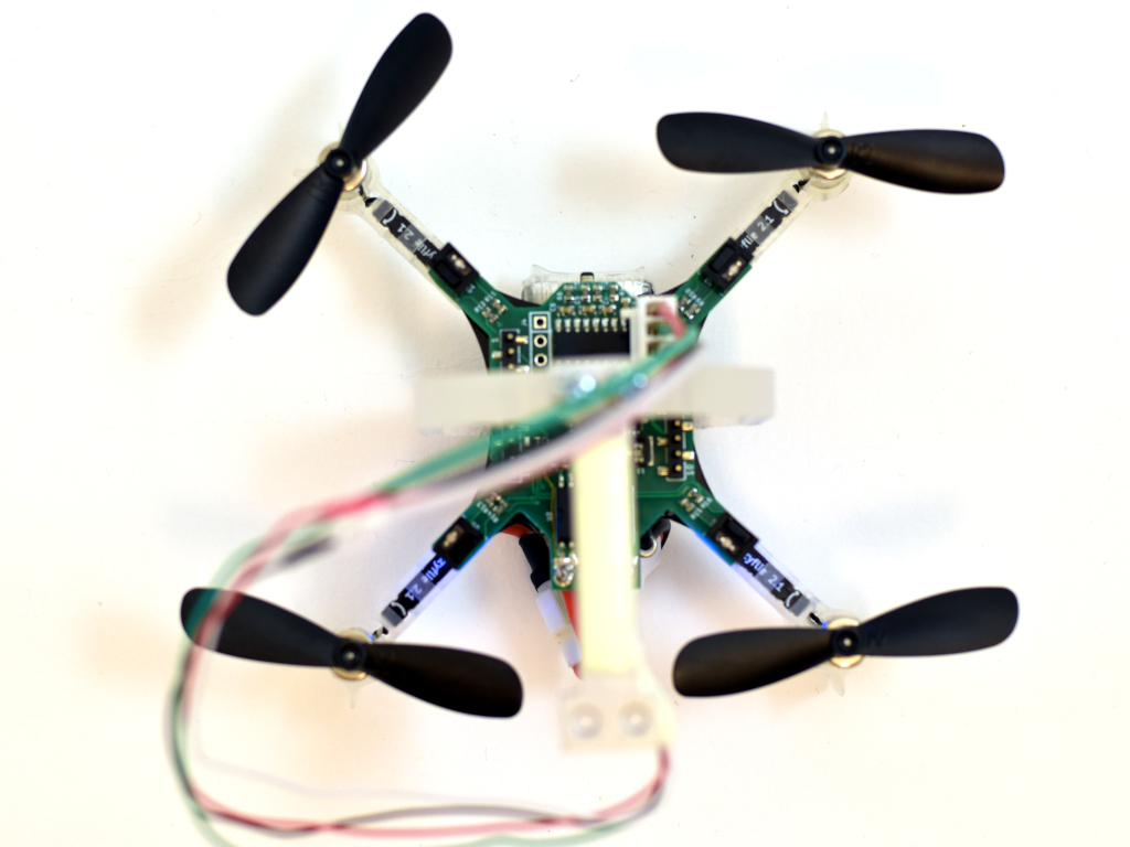
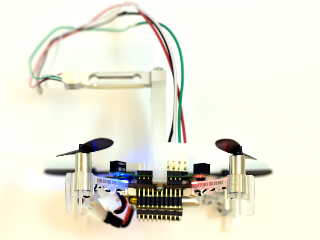
The PCB was designed as small as possible so it could be mounted on a Crazyflie 2.X and used while flying. A bonus would be if it could be used on a Bolt as well.
Here it is mounted on a Crazyflie 2.1 together with a 3D printed stand and load cell.
The load cell would then be mounted to a desk or similar so the the Crazyflie is mounted up-side down, pushing down on the load cell.
Software
The software, as often, took most of the time to make. Three major deck driver files was created, rpm.c, acs37800.c and loadcell_nau7802.c. Aside from these there where only small changes to make, like making it work when being up-side-down. The modifications have all been pushed to the dev-systemid branch for those that are interested. As for now we are mainly using the logging framework to transfer the data to the PC, which is quick and easy to setup and use, but writing to SD-card is also possible. The scripts for this can be found in the tools/sytem_id folder.
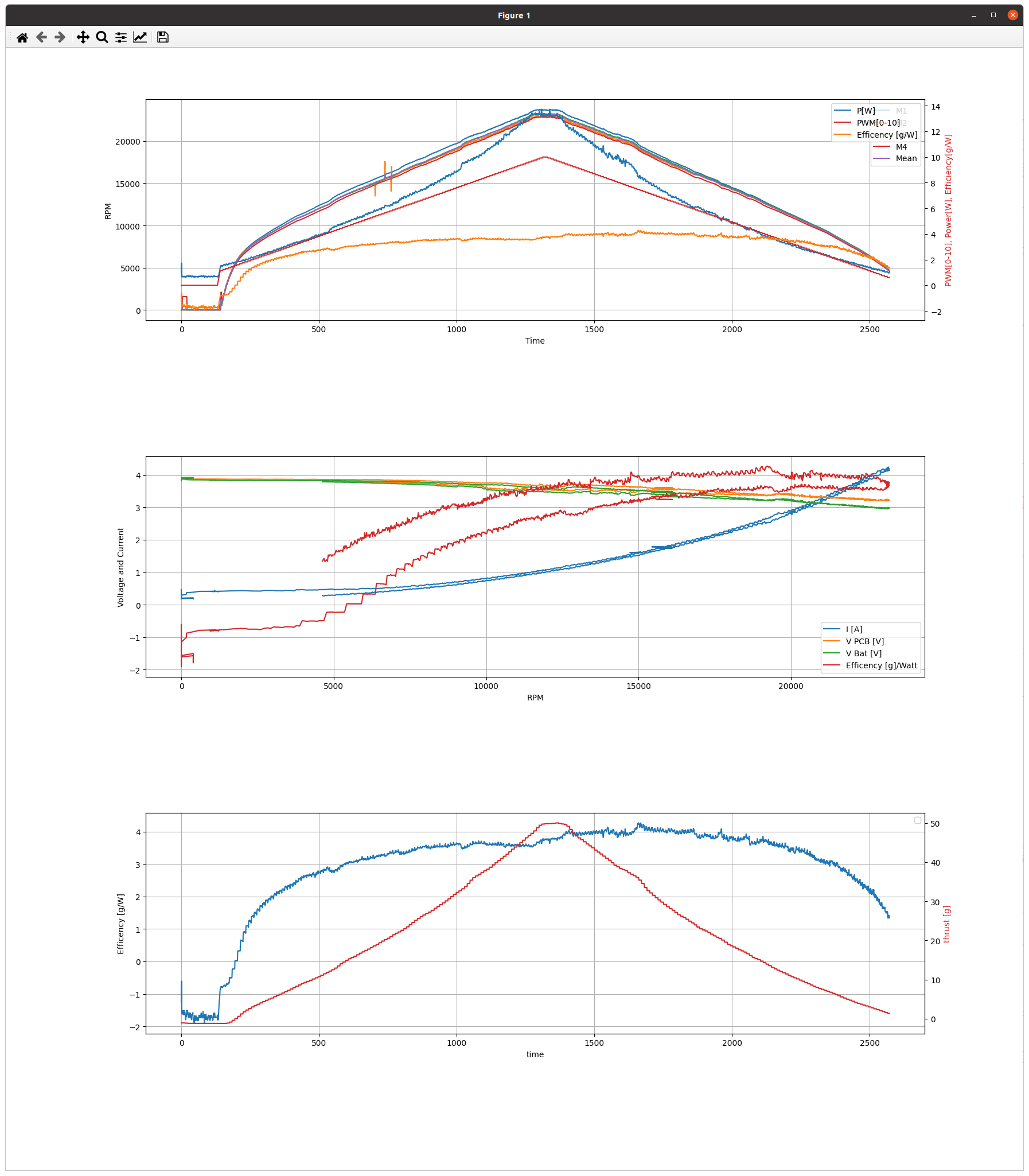
Remaining work is to test, gather and analyse more data. When we have done so, we will post more. Until then below is a sample of what it can measure. The data is taken with a ramping PWM from 0% – 100% – 0%. The added resistance of the extra wires and connectors are not taken into account, but the estimated efficiency of 4g/W is probably not that far off.
How to handle our documentation has been always a bit of struggle. For almost 2 years (see this blogpost and this one) we have working on improving the documentation structure, with by transferring information from the wiki, putting information closer to the code and setting up automating documentation. A few months ago, we managed to have automated logging and parameter documentation (see this blogpost).
Even though we think there is some improvement already, it can always be better! We have noticed that some of our users are a bit confused of how to go through our documentation. So in this blogpost we are discussing some navigational strategies of how you can maneuver yourself through the documentation as it is presented on bitcraze.io, which can also be found here.
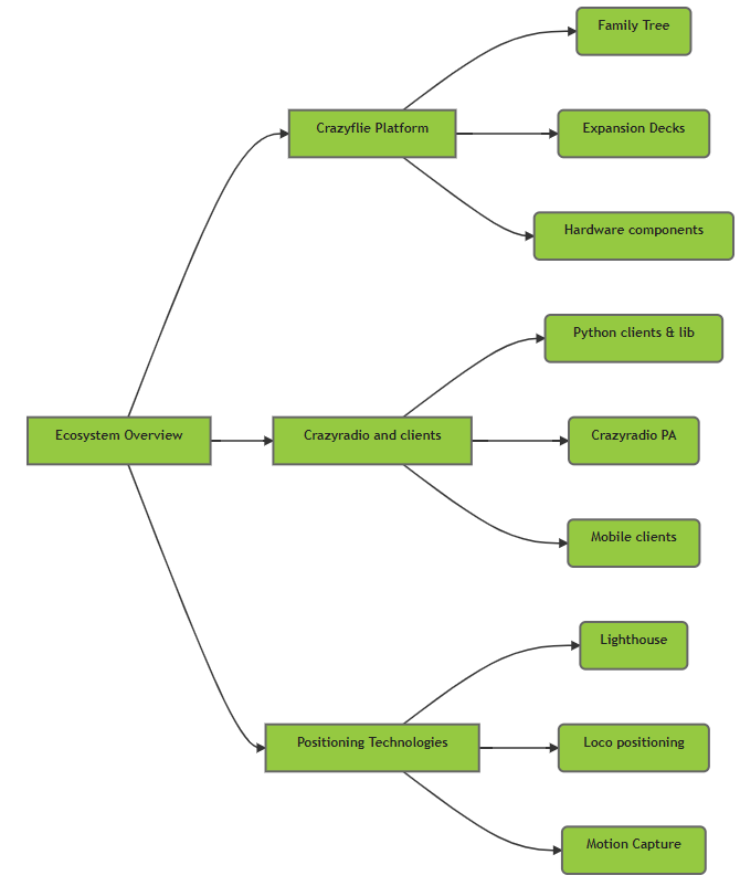
Ecosystem-based navigation
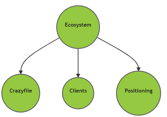
So more than a year ago, we also started with a Ecosystem overview page, which are meant to take first-timers by the hand through the Crazyflie ecosystem.. This type of overview pages are starting from the three main pillars: the Crazyflie Platform, the Clients and Positioning Technology. This is a type of navigation that we mostly advise to take if you are a beginner Crazyflie user who do not know the structure of the eco system fully.
For those that already have experience with the Crazyflie and its Ecosystem, the previous way of navigating through the docs might be a bit convoluted. With the Ecosystem-based navigation, it takes about 3 scrolls and clicks to reach the STM development documentation, which is a bit to much of a round way if you already know what you are looking for. We have made the repository overview page not for this purpose but we actually started using ourselves a lot within the company, as a direct pathway to the development repository per element. So this is a page that would be useful to other advanced developers as well!
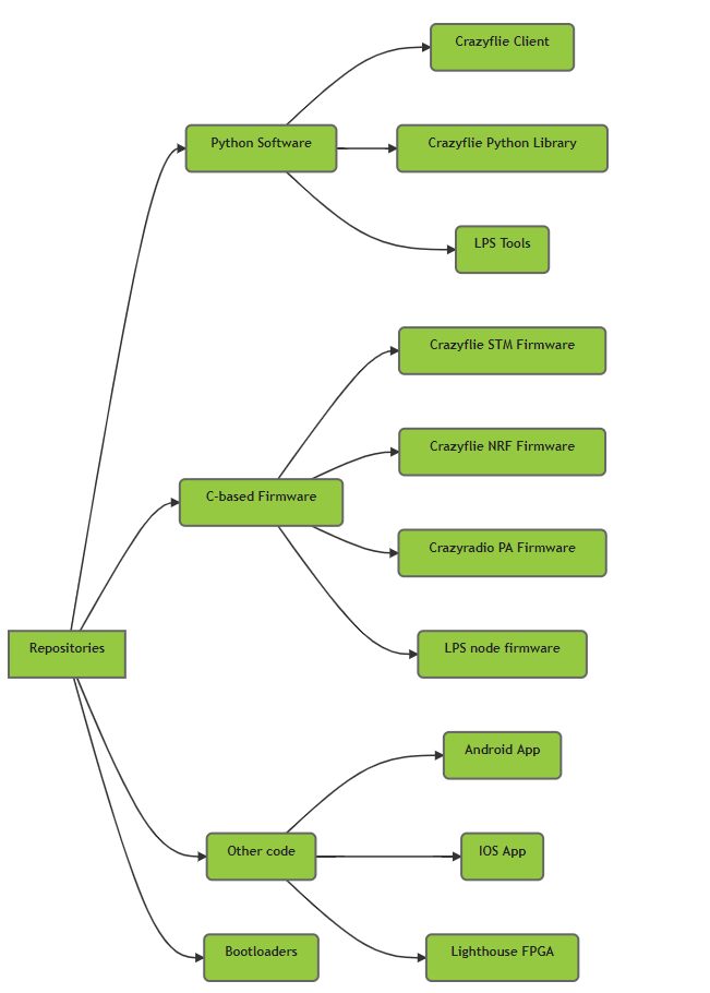
So the repository overview page is split up in 4 main categories: Python-based software, C-based firmware, Other languages and bootloaders. See the navigation tree which of those repositories approximately point too. By the way, have you noticed that repository documentation has a gray header (like this one) and all the overview pages on the web have a green header (like this one)? This are meant to make you aware if you are still on a fluffy overview website page or going in the nitty gritty details of the development documentation.
Repository-based navigation tree
Feature-based navigation ?
Still a remaining problem is that the repository documentation might not be enough to get a good overview. Where do you need to look if you are interested in ‘controllers’ or ‘state estimators’, or how to make an app-layer application? Currently all of this is within the stm32 firmware documentation, as that is the exact location of where all of this is implemented. But how to document spanning features like the CRTP, where not only the STM chip but also the NRF, Crazyradio PA and the Crazyflie python library are also involved? Or how about the loco positioning system, where the Crazyflie communicates through the LPS deck with a separate LPS node?
So perhaps a good way how to present all this information, is to do it feature-based, like ‘controllers’, ‘positioning’, ‘high level commander’, where we present a structure that points to parts of the detailed documentation within the repo-docs. With ecosystem-based, or even repository-based, navigation documentation strategy, it will take for instance 4-7 clicks to come to the specific controller page, as you can verify by looking at the bread-crumb of the header. Perhaps splitting it up based on feature instead of Ecosystem elements or programming language might be a more logical structure of the current state of the Crazyflie documentation.
Feedback
One reason why it is so difficult to do this properly, is that we have a lot of repositories based on each microprocessor of all of our products, which makes our opensource projects quite unique. It is therefore difficult to find another opensource project of which we can take inspiration from. So, let us know what you would prefer for navigating through our documentation in this poll, but we are always open to other suggestions! If you know of any example of a similar opensource software project that is doing it the right way, or have any other tips, send us an email (contact_at_bitcraze.io), contact us on social media platforms or post a comment on this blogpost!
Update 2021-12-21:
The poll is closed and this is the result! Thanks all for responding!
We like to describe the Crazyflie as a versatile open source flying development platform. It is something that enables you to do cool stuff. It is not a finished, polished end product in its own.
This approach makes determining the expectations and requirements for the platform and the surrounding ecosystem a bit tricky. It is dependent on what you as a user plan to create using our products. And since the ecosystem is growing we need a, scalable, way to handle these fuzzy expectations during development and maintenance.
We think testing is big part of solving this, testing in a systematic, scalable and reproducible way. This is the reason for setting up our first physical test lab, aimed at providing stability while moving forward with new products and features.
Testing today
Continuous integration
On each change proposal to our software we run tests. For the firmware in the device we build multiple different configuration and run unit-tests. For the Crazyflie client and the Python library we make sure we can build for Linux and Windows and that the code passes our style guidelines. If any test fail we go back and update the proposed changed and re-run the tests. This is our first level of defense against defects.
Release testing
For each release we follow a checklist of procedures and tests to make sure that quality does not degrade. We make sure all the examples in the Python library are working and that the Crazyflie can fly around as expected in our flight arena, using various positioning systems.
Limitations
The way we test today makes it very difficult to determine if we regress in, for example, flight capability or in radio communication quality. We either test different software packages in isolation, without hardware in the loop, or we test by having a human trying to estimate if any degradation has happened since the last release.
We run into scalability issues as our ecosystem grows, it is near impossible to test all the different combinations of products. And it is very hard for us to detect stability or quality regressions without having a more systematic approach to testing the software on relevant hardware.
Introducing the test lab
What we have done so far are two things:
Created an infrastructure for setting up a site for testing our software on real devices
Prepared a test lab in our printer room at our office in Malmö
This new Git repository contains the building blocks we need to setup our new test lab. You can check out the repository README.md file for information on how to run it.
The repository contains a way to specify a test site, which is a collection of devices to run the test suite against. You specify your site in a TOML file which contain information about each device, such as which decks are connected and the radio:// URI. This site specification is then used by the test framework when running the tests, making sure each test is run against all devices compatible with that test.
The infrastructure also has management scripts to perform tasks like flashing all devices in a site, or recovering them if they go into boot loader mode by accident. All aimed at being able to handle testing with the least amount of human intervention possible.
This acts as a safety net for us. We will quickly know if the communication performance degrades, or if we have messed up with our parameter or logging frameworks. And we can catch silly firmware bugs as early as possible.
Future
We want to keep adding test cases and other infrastructure to our testing framework. Going forward it would be really nice to be able to test positioning systems in some way. And of course, some type of test of flight, be it free flying tests or using some kind of harness.
It might be interesting to look into adding simulations (hardware in loop or not) to our testing setup. It is all a question of bandwidth, there are a lot of cool things to work on, and a limit on time and bodies.
You can help! You might even be able to help yourself while helping us! If you contribute tests that correspond to your use-case, then you can relax knowing that those tests will run each night, and that Bitcraze engineers will be notified the minute they fail.
Or you can define your own site and run the test-suite against all your devices to make sure nothing strange is going on.
Hopefully this infrastructure and lab will help all of us to do more cool stuff using the Bitcraze ecosystem!
Ever since we released the Lighthouse deck back in 2019, we’ve wanted to offer a bundle with the deck and the base stations. There’s multiple reasons for this, but the main reason was that we wanted users to be able to buy a full swarm (like the Loco Positioning Swarm) directly from us, without having to find the base stations separately. Initially this seemed easy to do, but it turned out to be a bit tricky. This post is about how we finally managed to get the Lighthouse Swarm Bundle finished and into the E-store.
The Lighthouse swarm bundle
When the Lighthouse deck was initially released it only had support for Lighthouse V1 base stations, but Ligthouse V2 was already out. Since the V1 base stations were already in short supply, we wanted to support V2 since this was what would be available in the future. We had started looking at V2 support, but there was still ongoing efforts from us (and others) to reverse engineer the protocol. After some prototyping we had some initial support, but there was still a lot of infrastructure work to be done before it could be released.
In parallell with this work we started trying to buy the Lighthouse V2 base stations. Normally there’s two options here, either buy from local distributors or buy directly from the manufacturer. Buying from local distributors wasn’t a good option for us since these will only have local power plugs and buying directly from the manufacturer often requires very large orders. So this process quickly stalled. But after a couple of months we got an offer to buy a bulk shipment of Ligthouse V2 base stations (without box or power adapters) which we finally decided to accept. And yeah, that’s me looking really happy next to a bunch of base stations…
Marcus looking happy about the base stations
With a bunch of base stations at the office, work with sourcing a power adapter and creating a box started. Unfortunately the number of COVID-19 cases started rising again shortly after receiving the base stations, so we started working more from home again. And with only 2 persons at the office at a time, it’s hard to work with hardware. Different team-members needs access to different resources, like the electronics labs, flight arena or packing orders. So getting box/adapter samples from manufacturers, doing testing and getting input on physical objects from other team-members quickly went from days to weeks.
Finally, after a couple of months of testing, evaluating and learning lots about adapters and cardboard, we had good candidates. But then, literally as we’re ordering the power adapters, it turns out the certification was not good for all the regions we wanted. Thankfully this time around we already had other options so we quickly decided on the second best option (now the best option) and ordered.
In the meantime work was underway finalizing the implementation of Lighthouse V2, including client support, firmware updates of the Lighthouse deck and documentation/videos. Finally in the beginning of 2021 we got documentation and the full implementation (although only for 2 base stations) in place (blog post).
After a bit more than a month of waiting, the power adapters and boxes finally showed up at our office. With all the supplies in place, we started preparing for the packing. Since you can buy base stations for multiple sources, we wanted to keep track of the base stations that we were sending out to be able to debug issues users might have with these units. Also, even though the base stations had already been factory tested, we wanted to quickly test them before shipping them out. So our flight arena was turned into a makeshift assembly line and we had some outside help come in to do the packing.
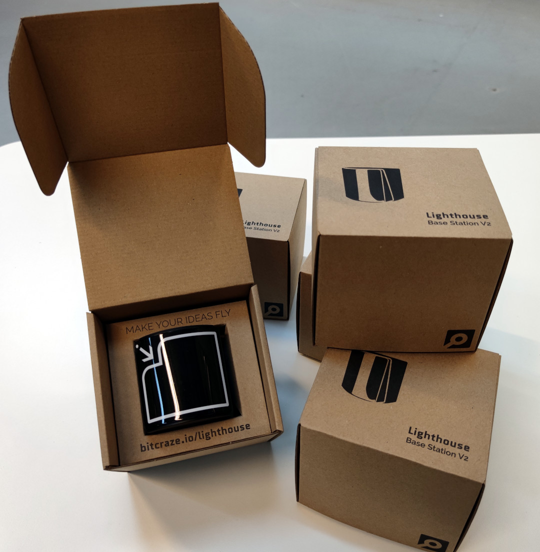
Finally, the end result! We’re really excited to be able to offer yet another swarm bundle, the Lighthouse swarm bundle. And we’re pretty happy about how the packaging turned out :-)
This week we have a guest blog post from Bart Duisterhof and Prof. Guido de Croon from the MAVlab, Faculty of Aerospace Engineering from the Delft University of Technology. Enjoy!
Tiny drones are ideal candidates for fully autonomous jobs that are too dangerous or time-consuming for humans. A commonly shared dream would be to have swarms of such drones help in search-and-rescue scenarios, for instance to localize gas leaks without endangering human lives. Drones like the CrazyFlie are ideal for such tasks, since they are small enough to navigate in narrow spaces, safe, agile, and very inexpensive. However, their small footprint also makes the design of an autonomous swarm extremely challenging, both from a software and hardware perspective.
From a software perspective, it is really challenging to come up with an algorithm capable of autonomous and collaborative navigation within such tight resource constraints. State-of-the-art solutions like SLAM require too much memory and processing power. A promising line of work is to use bug algorithms [1], which can be implemented as computationally efficient finite state machines (FSMs), and can navigate around obstacles without requiring a map.
A downside of using FSMs is that the resulting behavior can be very sensitive to their hyperparameters, and therefore may not generalize outside of the tested environments. This is especially true for the problem of gas source localization (GSL), as wind conditions and obstacle configurations drastically change the problem. In this blog post, we show how we tackled the complex problem of swarm GSL in cluttered environments by using a simple bug algorithm with evolved parameters, and then tested it onboard a fully autonomous swarm of CrazyFlies. We will focus on the problems that were encountered along the way, and the design choices we made as a result. At the end of this post, we will also add a short discussion about the future of nano drones.
Why gas source localization?
Overall we are interested in finding novel ways to enable autonomy on constrained devices, like CrazyFlies. Two years ago, we showed that a swarm of CrazyFlie drones was able to explore unknown, cluttered environments and come back to the base station. Since then, we have been working on an even more complex task: using such a swarm for Gas Source Localization (GSL).
There has been a lot of research focussing on autonomous GSL in robotics, since it is an important but very hard problem. The difficulty of the task comes from the complexity of how odor can spread in an environment. In an empty room without wind, a gas will slowly diffuse from the source. This can allow a robot to find it by moving up gradient, just like small bacteria like E. Coli do. However, if the environment becomes larger with many obstacles and walls, and wind comes into play, the spreading of gas is much less regular. Large parts of the environment may have no gas or wind at all, while at the same time there may be pockets of gas away from the source. Moreover, chemical sensors for robots are much less capable than the smelling organs of animals. Available chemical sensors for robots are typically less sensitive, noisier, and much slower.
Due to these difficulties, most work in the GSL field has focused on a single robot that has to find a gas source in environments that are relatively small and without obstacles. Relatively recently, there have been studies in which groups of robots solve this task in a collaborative fashion, for example with Particle Swarm Optimization (PSO). This allows robots to find the source and escape local maxima when present. Until now this concept has been shown in simulation [2] and on large outdoor drones equipped with LiDAR and GPS [3], but never before on tiny drones in complex, GPS-denied, indoor environments.
Required Infrastructure
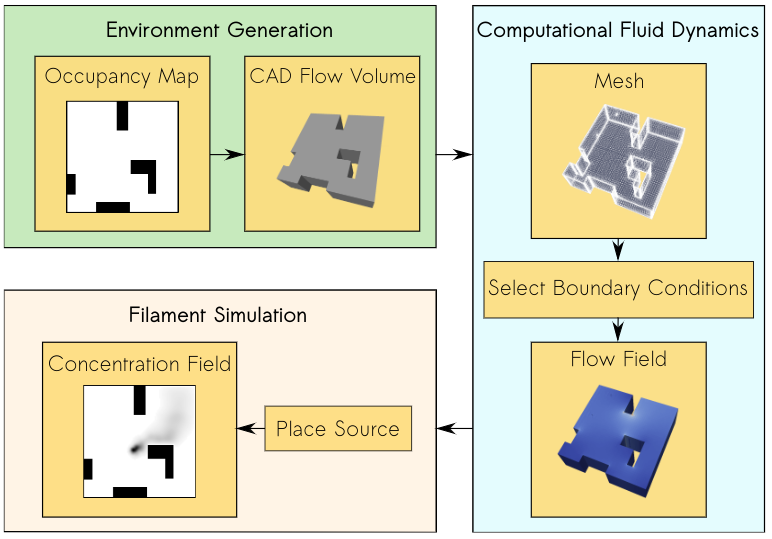
In our project, we introduce a new bug algorithm, Sniffy Bug, which uses PSO for gas source localization. In order to tune the FSM of Sniffy Bug, we used an artificial evolution. For time reasons, evolution typically takes place in simulation. However, early in the project, we realized that this would be a challenge, as no end-to-end gas modeling pipeline existed yet. It is important to have an easy-to-use pipeline that does not require any aerodynamics domain knowledge, such that as many researchers as possible can generate environments to test their algorithms. It would also make it easier to compare contributions and to better understand in which conditions certain algorithms work or don’t work. The GADEN ROS package [4] is a great open-source tool for modeling gas distribution when you have an environment and flow field, but for our objective, we needed a fully automated tool that could generate a great variety of random environments on-demand with just a few parameters. Below is an overview of our simulation pipeline: AutoGDM.
AutoGDM, a fully automated gas dispersion modeling (GDM) simulation pipeline.
First, we use a procedural environment generator proposed in [5] to generate random walls and obstacles inside of the environment. An important next step is to generate a 3D flowfield by means of computational fluid dynamics (CFD). A hard requirement for us was that AutoGDM needed to be free to use, so we chose to use the open-source CFD tool OpenFOAM. It’s used for cutting-edge aerodynamics research, and also the tool suggested by the authors of GADEN. Usually, using OpenFOAM isn’t trivial, as a large number of parameters need to be selected that require field expertise, resulting in a complicated process. Next, we integrate GADEN into our pipeline, to go from environment definition (CAD files) and a flow field to a gas concentration field. Other parts that needed to be automated were the random selection of boundary conditions, which has a large impact on the actual flow field, and source placement, which has an equally large impact on the concentration field.
After we built this pipeline, we started looking for a robot simulator to couple it to. Since we weren’t planning on using a camera, our main requirement was for the simulator to be efficient (preferably in 2D) so that evolutions would take relatively little time. We decided to use Swarmulator [6], a lightweight C++ robot simulator designed for swarming and we plugged in our gas data.
Algorithm Design
Roughly speaking, we considered two categories of algorithms for controlling the drones: 1) a neural network, and 2) an FSM that included PSO, with evolved parameters. Since we used a tiny neural network for light seeking with a CrazyFlie in our previous work, we first evolved neural networks in simulation. One of the first experiments is shown below.
A single agent in simulation seeking a light source using a tiny neural network.
While it worked pretty well in simple environments with few obstacles, it seemed challenging to make this work in real life with complex obstacles and multiple agents that need to collaborate. Given the time constraints of the project, we have opted for evolving the FSM. This also facilitated crossing the reality gap, as the simulated evolution could build on basic behaviors that we developed and validated on the real platform, including obstacle avoidance with four tiny laser rangers, while communicating with and avoiding other drones. An additional advantage of PSO with respect to the reality gap is that it only needs gas concentration and no gradient of the gas concentration or wind direction (which many algorithms in literature use). On a real robot at this scale, estimating the gas concentration gradient or the direction of a light breeze is hard if not impossible.
Hardware
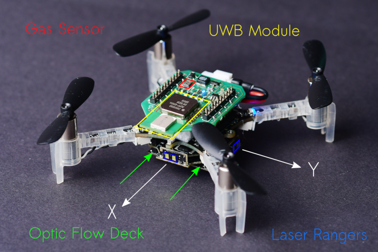
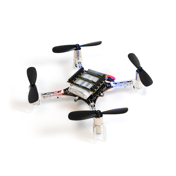
Our CrazyFlie needs to be able to avoid obstacles, execute velocity commands, sense gas, and estimate the other agent’s position in its own frame. For navigation, we added the flow deck and laser rangers, whereas for gas sensing we used a TGS8100 gas sensor that was used on a CrazyFlie before in previous work [7]. The sensor is lightweight and inexpensive, but accurately estimating gas concentrations can be difficult because of its size. It tends to drift and needs time to recover after a spike in concentration is observed. Another thing we noticed is that it is possible to break them, a crash can definitely destroy the sensor.
To estimate the relative position between agents, we use a Decawave Ultra-Wideband (UWB) module and communicate states, as proposed in [8]. We also use the UWB module to communicate gas information between agents and collaboratively seek the source. The complete configuration is visible below.
A 37.5 g nano quadcopter, capable of fully autonomous waypoint tracking, obstacle avoidance, relative localization, communication and gas sensing.
Evaluation in Simulation
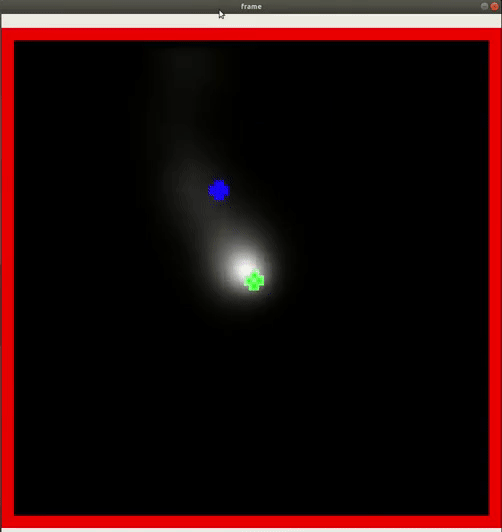
After we optimized the parameters of our model using Swarmulator and AutoGDM, and of course trying many different versions of our algorithm, we ended up with the final Sniffy Bug algorithm. Below is a video that shows evolved Sniffy Bug evaluated in six different environments. The red dots are an agent’s personal target waypoint, whereas the yellow dot is the best-known position for the swarm.
Sniffy Bug evaluated in Swarmulator environments.
Simulation showed that Sniffy Bug is effective at locating the gas source in randomly generated environments. The drones successfully collaborate by means of PSO.
Real Flight Testing
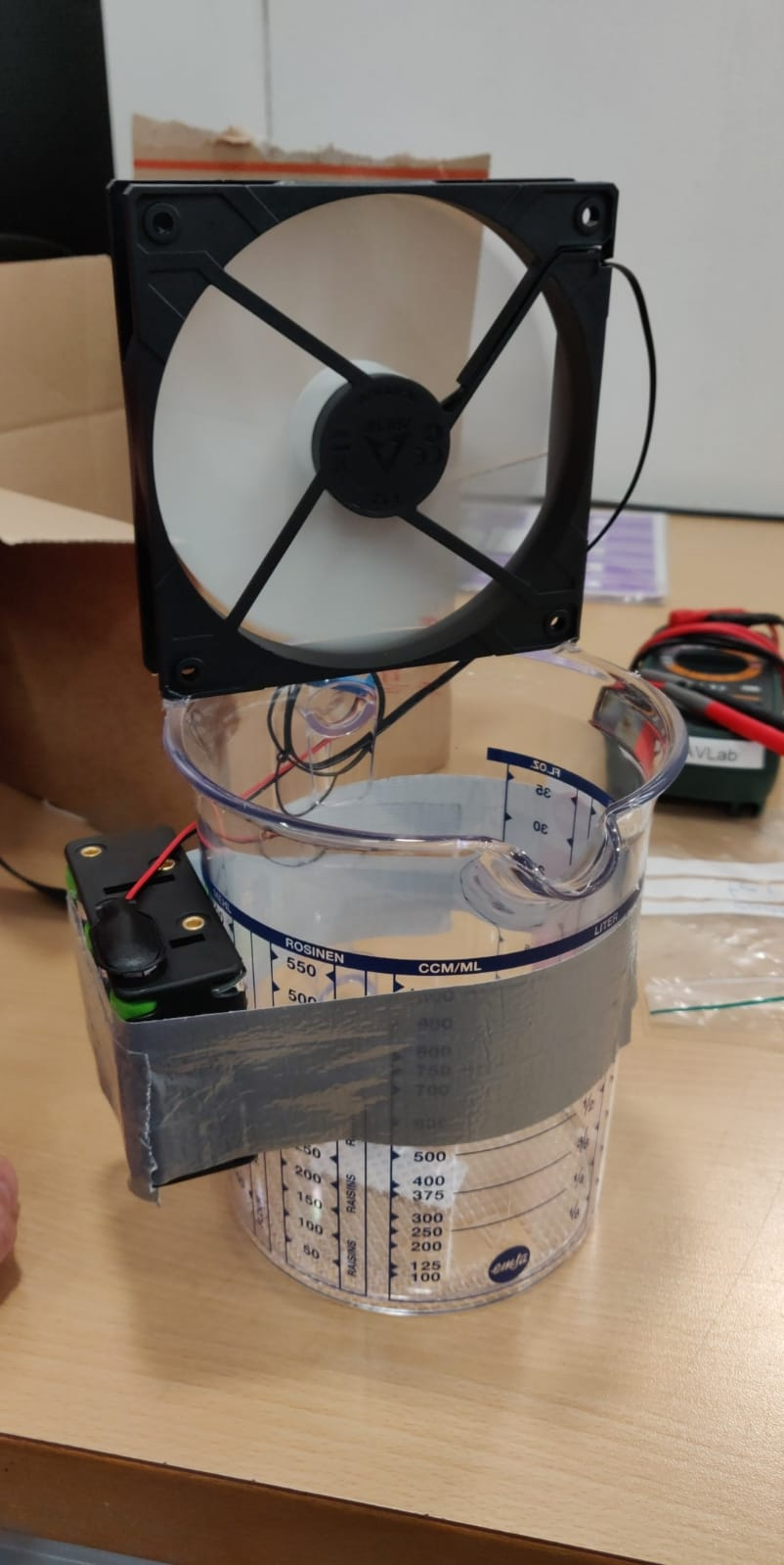
After observing Sniffy Bug in simulation we were optimistic, but unsure about performance in real life. First, inspired by previous works, we disperse alcohol through the air by placing liquid alcohol into a can which is then dispersed using a computer fan.
Dispersion of liquid alcohol in flight tests.
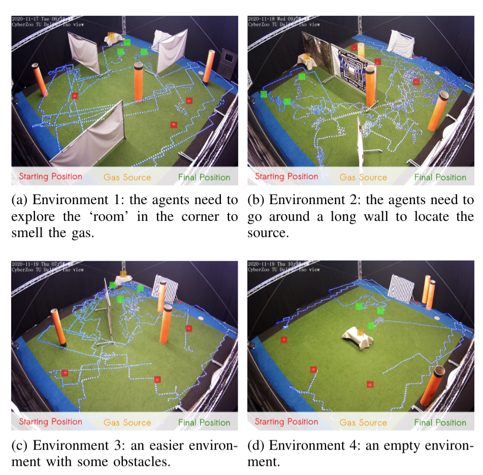
We test Sniffy Bug in our flight arena of size 10 x 10 meters with large obstacles that are shaped like walls and orange poles. The image below shows four flight tests of Sniffy Bug in cluttered environments, flying fully autonomously, i.e., without the help from any external infrastructure.
Time-lapse images of real-world experiments in our flight arena. Sniffy was evaluated on four distinct environments, 10 x 10 meters in size, seeking a real isopropyl alcohol source. The trajectories of the nano quadcopters are clearly visible due to their blue lights.
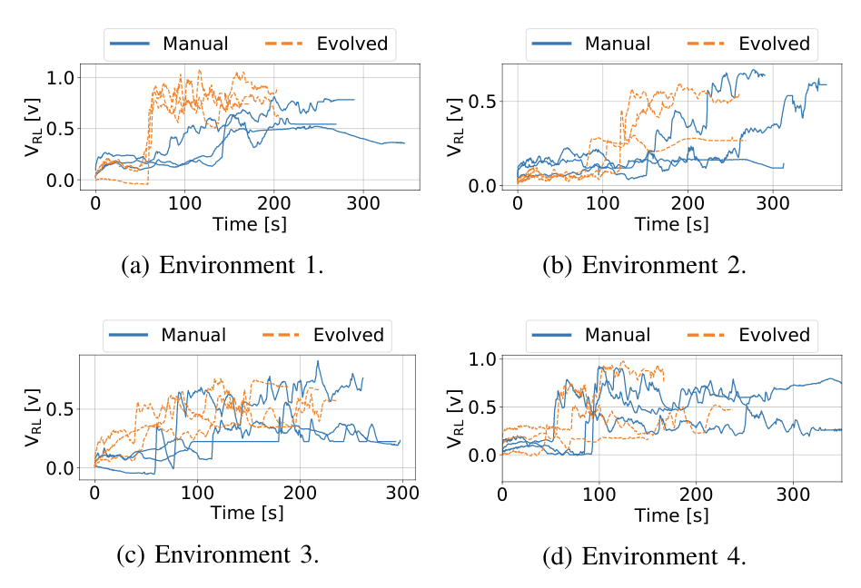
In the total of 24 runs we executed, we compared Sniffy Bug with manually selected and evolved parameters. The figure below shows that the evolved parameters are more efficient in locating the source as compared to the manual parameters.
Maximum recorded gas reading by the swarm, for each time step for each run.
This does not only show that our system can successfully locate a gas source in challenging environments, but it also demonstrates the usefulness of the simulation pipeline. The parameters that were learned in simulation yield a high-performance model, validating the environment generation, randomization, and gas modeling parts of our pipeline.
Conclusion and Discussion
With this work, we believe we have made an important step towards swarms of gas-seeking drones. The proposed solution is shown to work in real flight tests with obstacles, and without any external systems to help in localization or communication. We believe this methodology can be extended to larger environments or even to 3 dimensions, since PSO is a robust, multi-dimensional heuristic search method. Moreover, we hope that AutoGDM will help the community to better compare gas seeking algorithms, and to more easily learn parameters or models in simulation, and deploy them in the real world.
To improve Sniffy Bug’s performance, adding more laser rangers will definitely help. When working with only four laser rangers you realize how little information it actually provides. If one of the rangers senses a low value it is unclear if a slim pole or a massive wall is detected, adding inefficiency to the algorithm. Adding more laser rangers or using other sensor modalities like vision will help to avoid also more complex obstacles than walls and poles in a reliable manner.
Another interesting discussion can be held on the hardware required for real deployment. When working with 40 grams of maximum take-off weight, the sensors and actuators that can be selected are limited. For example, the low-power and lightweight flow deck works great but fails in low-light scenarios or with smoke. Future work exploring novel sensors for highly constrained nano robots could really help increase the Technological Readiness Level (TRL) of these systems.
Finally, this has been a really fun project to work on for us and we can’t wait to hear your thoughts on Sniffy Bug!
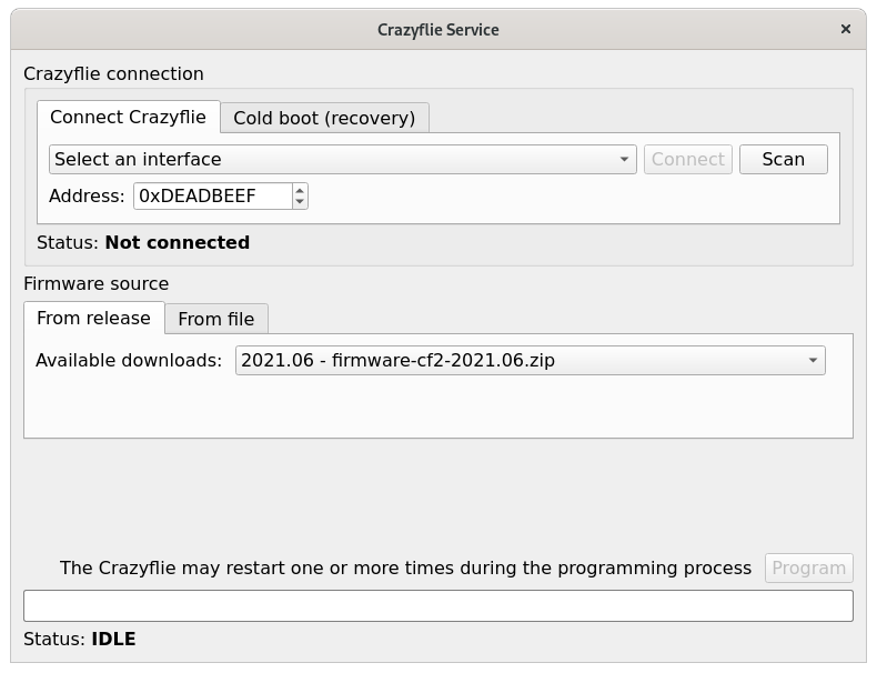
We are happy to announce the availability of the 2021.06 release of the Crazyflie firmware and client! This release includes bugfixes related to flashing the Crazyflie and the Lighthouse deck and also the new concept of core parameters and logging variables, that we talked about in the blog post: Crazyflie logging and parameters interface.
We always strive to release quality software and firmware, but we are not perfect! Please help us out by installing the new library, client and firmware and make sure that your applications, tools and algorithms still work as you expect! And if not please file an issue with us or contact us via the forum.
If you haven’t visited our store in a while, you may have missed our new addition: the Lighthouse Swarm bundle!
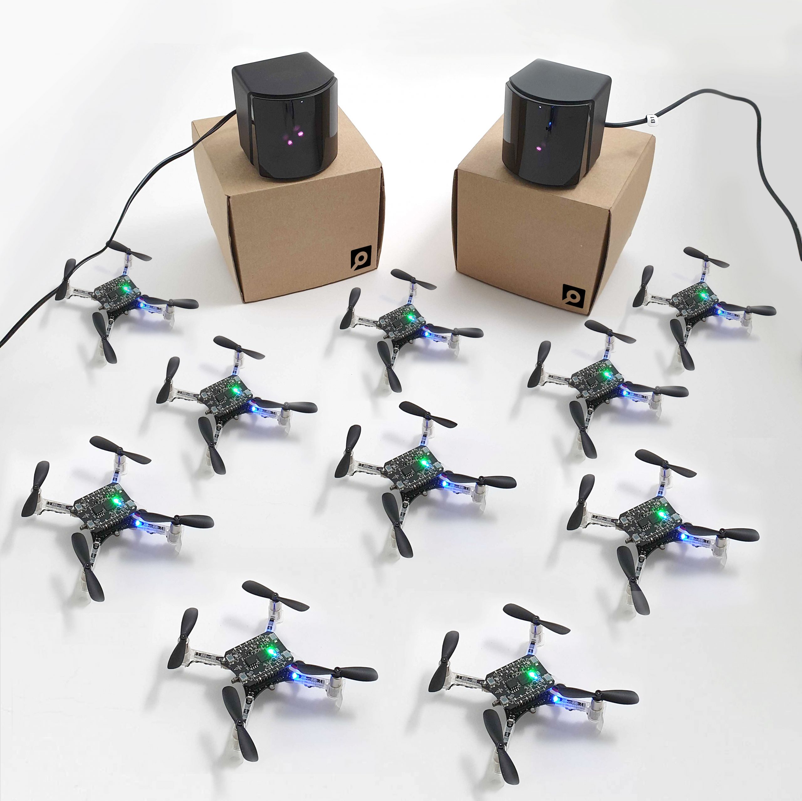
We’ve been working for some time now on improving the Lighthouse decks and its positioning system. Earlier in the year, we have brought the Lighthouse deck out of early access. While working with it, we have seen the great possibilities and the accuracy of this new positioning system. Thanks to Steam’s VR base station that we use as an optical beacon, the Crazyflie calculates its position with an accuracy better than a decimeter and millimeter precision. It gives a tracking volume of up to 5x5x2 meters with sub-millimetre jitter and below 10 cm accuracy while flying. It’s perfect for a swarm, as it’s accurate, precise and autonomous. We’ve flown our Crazyflies with it a number of time and seen some awesome stuff with it!
As an example, here is a demo we’ve shown on a conference back in October. We’ve used 8 Crazyflies equipped with Lighthouse decks and Qi chargers, to make a spiraling swarm. A computer orchestrates the Crazyflies and make sure one is flying at all times, while the others re-charge their batteries on their pads. After a pre-programmed trajectory is finished or when the battery of the flying Crazyflie is depleted, it goes back to its pad while another one takes over. The demo had an all-in mode that runs the trajectory on all Crazyflie with sufficient charge at once, the result is quite impressive and demonstrate the great relative precision of the Lighthouse system:
After the launch signal is sent to the Crazyflies, the computer is not required anymore: the Crazyflie will autonomously estimate its position from the lighthouse’s signals. The Crazyflie can estimate its own X, Y and Z in a global coordinate system.
What’s great with the Lighthouse Swarm is that it allows you to do drone research even if you’re on a tighter budget.
And when we got the opportunity to acquire our own base stations (that are also available in the shop by the way), it seemed only logical to offer a Swarm bundle similar to our Loco swarm bundle. So what’s in it ?
While the positioning will work with one base station, two base stations will allow better coverage of the flight space and better stability; as Kimberly can attest, it’s even possible to set it in your kitchen. The Crazyradios allow communication between the Crazyflies and your computer.
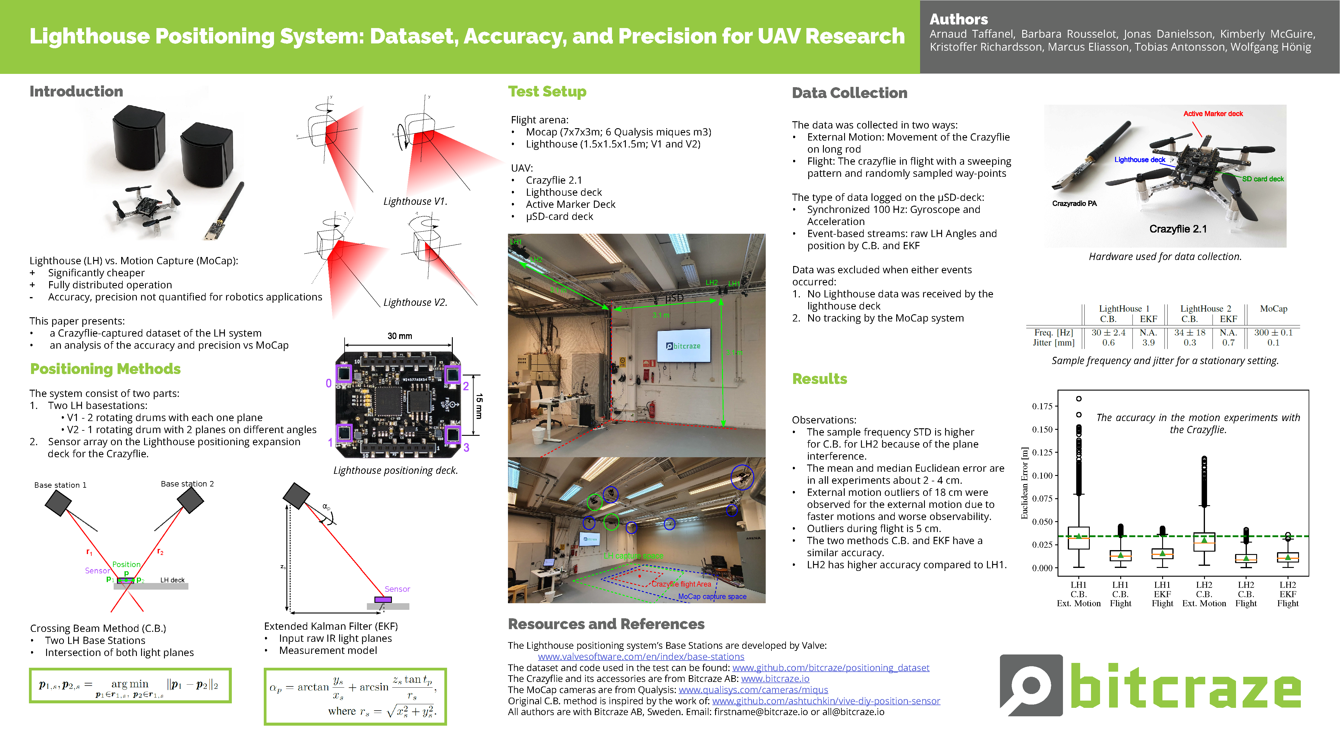
We dedicated a lot of time to the Lighthouse this winter, writing a paper with the help of Wolgangs’ calibration expertise. In this paper, we compared both Lighthouse V1 and V2 with the MoCap system. In all cases, the mean and median Euclidean error of the Lighthouse positioning system are about 2-4 centimeters compared to our MoCap system as ground truth. You can check the paper here, but here is a brief summary we used for our ICRA workshop:
The poster presenting our paper
We are now quite excited to get to see what you will do with this exciting new swarm bundle !
And if you don’t know how to set up the Swarm, you can get started at least with your Lighthouse system in this tutorial or watch Kristoffer explain it in this video:
This week we have a guest blog post from Dr Feng Shan at School of Computer Science and Engineering Southeast University, China. Enjoy!
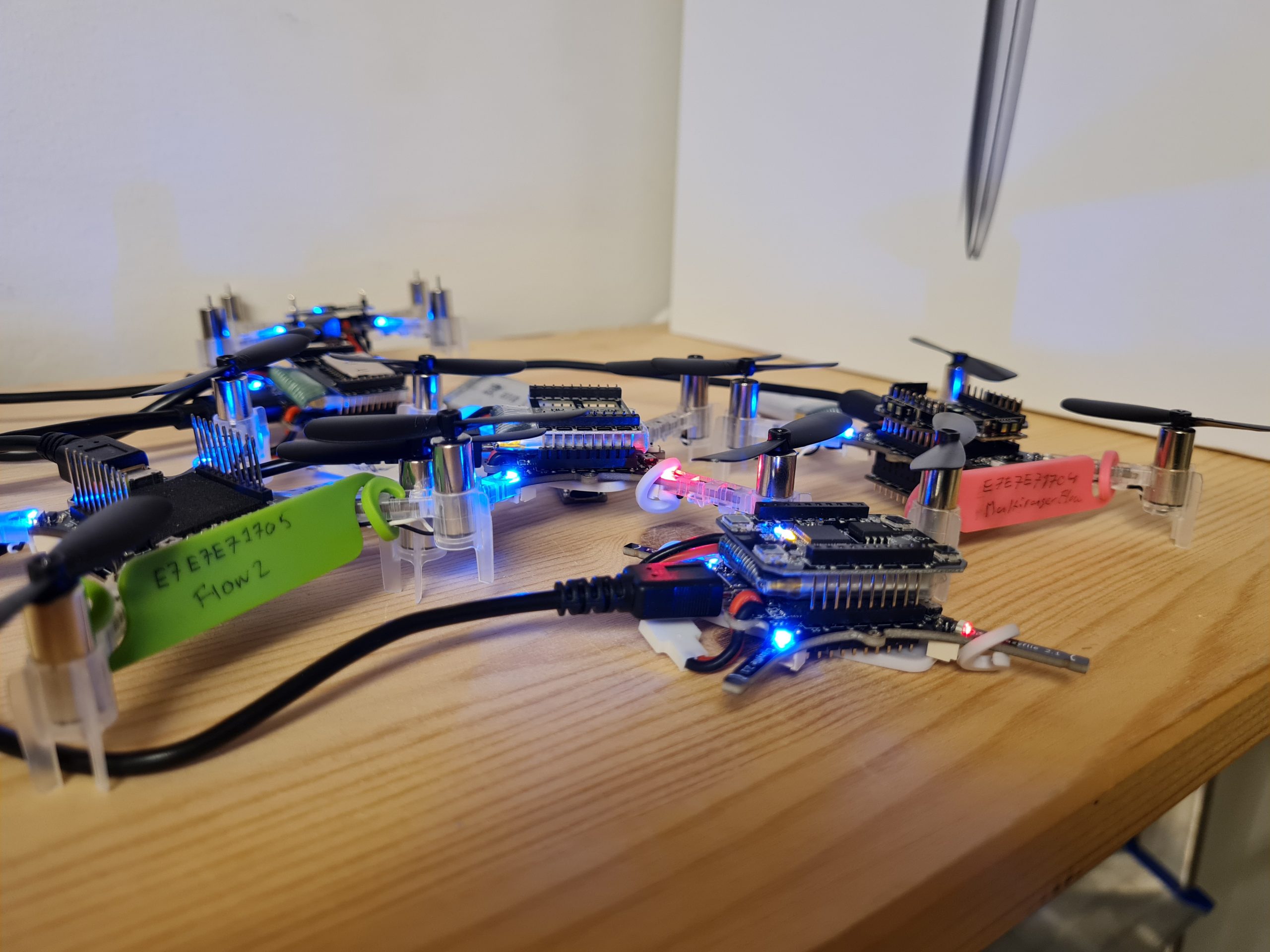
It is possible to utilize tens and thousands of Crazyflies to form a swarm to complete complicated cooperative tasks, such as searching and mapping. These Crazyflies are in short distance to each other and may move dynamically, so we study the dynamic and dense swarms. The ultra-wideband (UWB) technology is proposed to serve as the fundamental technique for both networking and localization, because UWB is so time sensitive that an accurate distance can be calculated using the transmission and receive timestamps of data packets. We have therefore designed a UWB Swarm Ranging Protocol with key features: simple yet efficient, adaptive and robust, scalable and supportive. It is implemented on Crazyflie 2.1 with onboard UWB wireless transceiver chips DW1000.
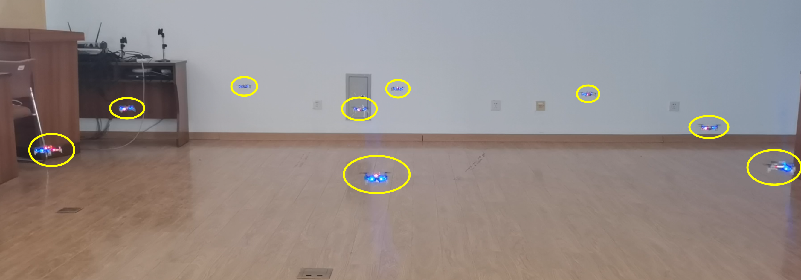
Fig.1. Nine Crazyflies are in a compact space ranging the distance with each other.
The Basic Idea
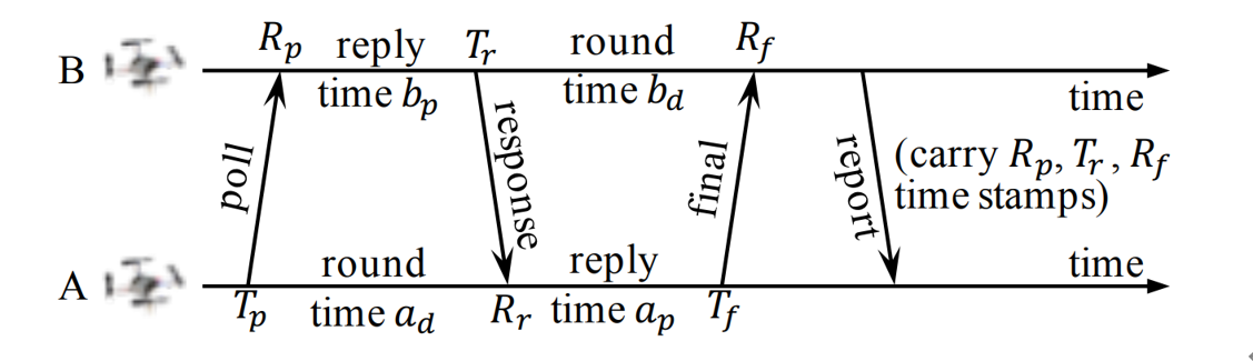
The basic idea of the swarm ranging protocol was inspired by Double Sided-Two Way Ranging (DS-TWR), as shown below.
Fig.2. The exsiting Double Sided-Two Way Ranging (DS-TWR) protocol.
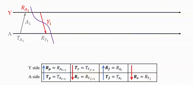
There are four types of message in DS-TWR, i.e., poll, response, final and report message, exchanging between the two sides, A and B. We define their transmission and receive timestamps are Tp, Rp, Tr, Rr, Tf, and Rf, respectively. We define the reply and round time duration for the two sides as follows.
Let tp be the time of flight (ToF), namely radio signal propagation time. ToF can be calculated as Eq. (2).
Then, the distance can be estimated by the ToF.
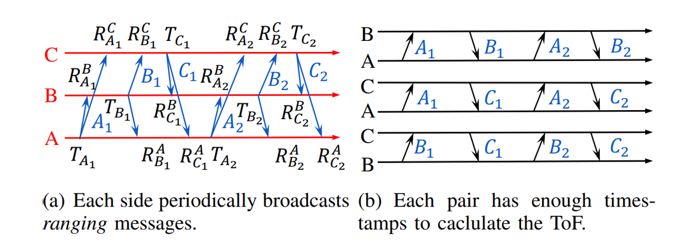
In our proposed Swarm Ranging Protocol, instead of four types of messages, we use only one type of message, which we call the ranging message.
Fig.3. The basic idea of the proposed Swarm Ranging Protocol.
Three sides A, B and C take turns to transmit six messages, namely A1, B1, C1, A2, B2, and C2. Each message can be received by the other two sides because of the broadcast nature of wireless communication. Then every message generates three timestamps, i.e., one transmission and two receive timestamps, as shown in Fig.3(a). We can see that each pair has two rounds of message exchange as shown in Fig.3(b). Hence, there are sufficient timestamps to calculate the ToF for each pair, that means all three pairs can be ranged with each side transmitting only two messages. This observation inspires us to design our ranging protocol.
Protocol Design
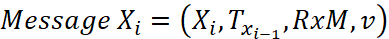
The formal definition of the i-th ranging message that broadcasted by Crazyflie X is as follows.
Xi is the message identification, e.g., sender and sequence number; Txi-1 is the transmission timestamp of Xi-1, i.e., the last sent message; RxM is the set of receive timestamps and their message identification, e.g., RxM = {(A2, RA2), (B2, RB2)}; v is the velocity of X when it generates message Xi.
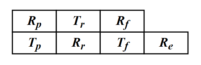
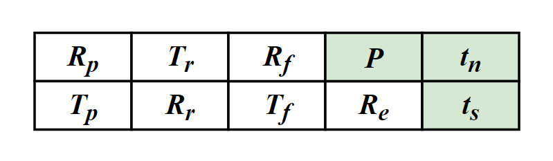
As mentioned above, six timestamps (Tp, Rp, Tr, Rr, Tf, Rf,) are needed to calculate the ToF. Therefore, for each neighbor, an additional data structure is designed to store these timestamps which we named it the ranging table, as shown in Fig.4. Each device maintains one ranging table for each known neighbor to store the timestamps required for ranging.
Fig.4. The ranging table, one for each neighbor.
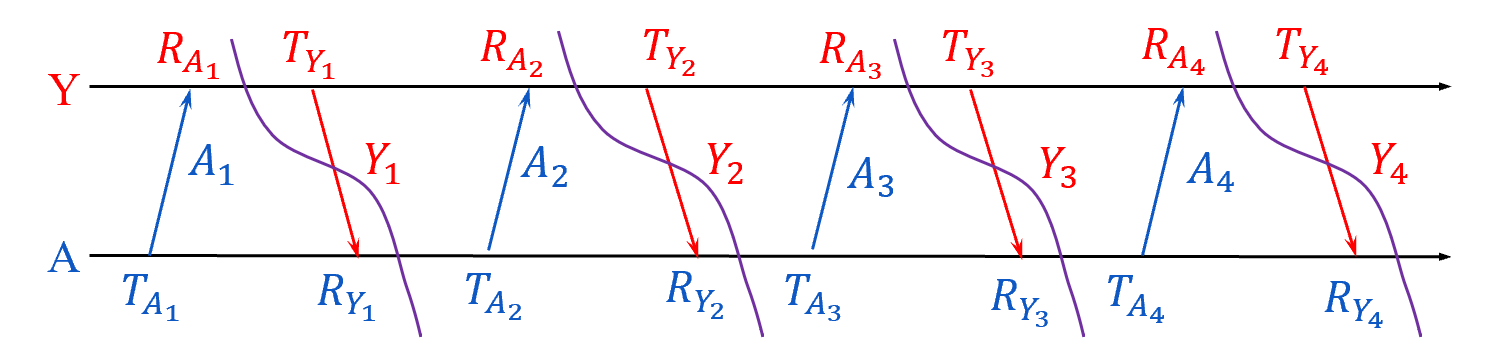
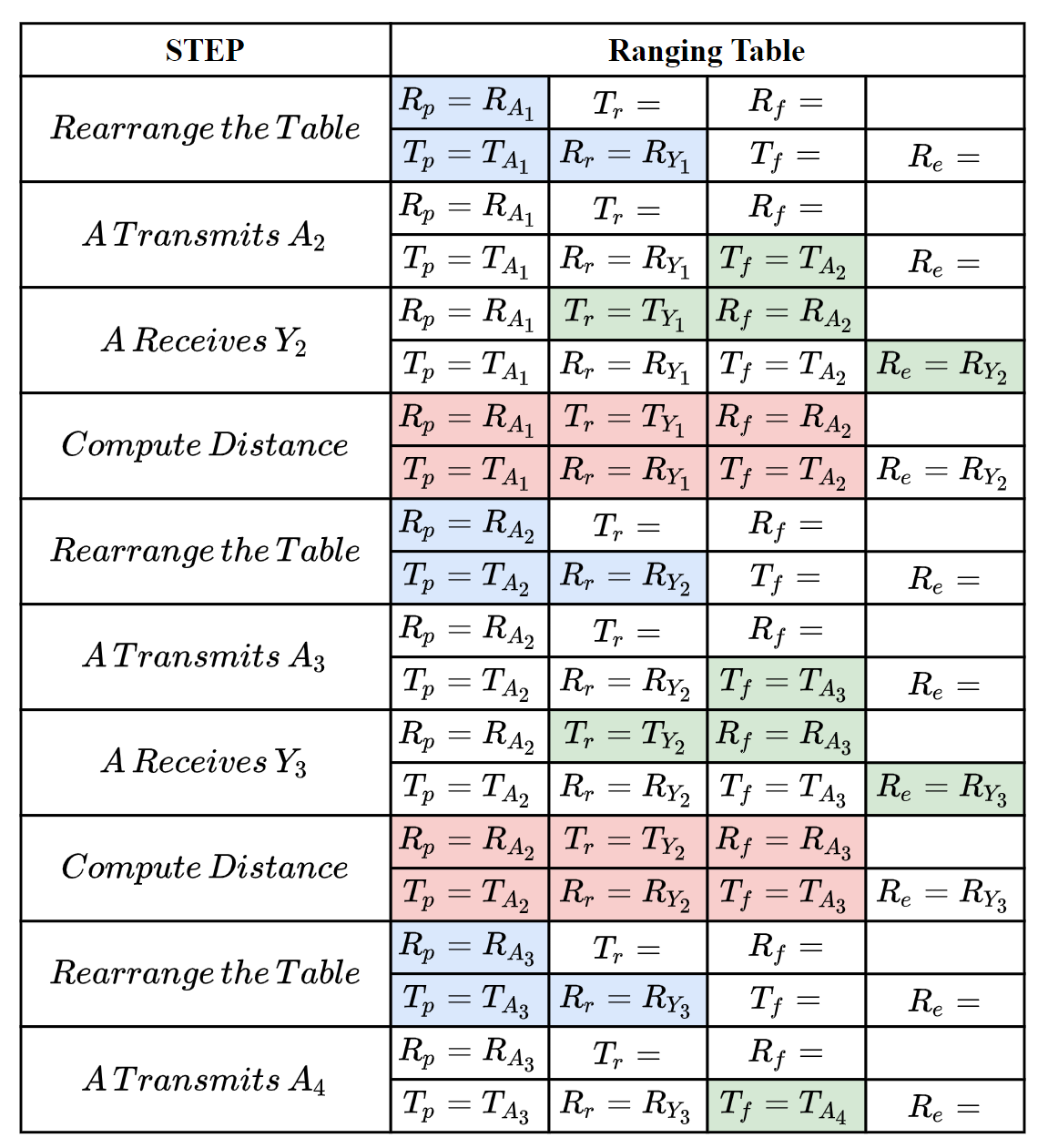
Let’s focus on a simple scenario where there are a number of Crazyflies, A, B, C, etc, in a short distance. Each one of them transmit a message that can be heard by all others, and they broadcast ranging messages at the same pace. As a result, between any two consecutive message transmission, a Crazyflie can hear messages from all others. The message exchange between A and Y is as follows.
Fig.5. Message exchange between A and Y.
The following steps show how the ranging messages are generated and the ranging tables are updated to correctly compute the distance between A and Y.
Fig.6. How the ranging message and ranging table works to compute distance.
The message exchange between A and Y could be also A and B, A and C, etc, because they are equal, that’s means A could perform the ranging process above with all of it’s neighbors at the same time.
To handle dense and dynamic swarm, we improved the data structure of ranging table.
Fig.7. The improved ranging table for dense and dynamic swarm.
There are three new notations P, tn, ts, denoting the newest ranging period, the next (expected) delivery time and the expiration time, respectively.
For any Crazyflie, we allow it to have different ranging period for different neighbors, instead of setting a constant period for all neighbors. So, not all neighbors’ timestamps are required to be carried in every ranging message, e.g., the receive timestamp to a far apart and motionless neighbor is required less often. tn is used to measure the priority of neighbors. Also, when a neighbor is not heard for a certain duration, we set it as expired and will remove its ranging table.
If you are interested in our protocol, you can find much more details in our paper, that has just been published on IEEE International Conference on Computer Communications (INFOCOM) 2021. Please refer the links at the bottom of this article for our paper.
Implementation
We have implemented our swarm ranging protocol for Crazyflie and it is now open-source. Note that we have also implemented the Optimized Link State Routing (OLSR) protocol, and the ranging messages are one of the OLSR messages type. So the “Timestamp Message” in the source file is the ranging message introduced in this article.
The procedure that handles the ranging messages is triggered by the hardware interruption of DW1000. During such procedure, timestamps in ranging tables are updated accordingly. Once a neighbor’s ranging table is complete, the distance is calculated and then the ranging table is rearranged.
All our codes are stored in the folder crazyflie-firmware/src/deck/drivers/src/swarming.
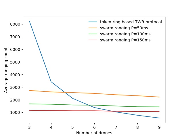
The following figure is a ranging performance comparison between our ranging protocol and token-ring based TWR protocol. It’s clear that our protocol handles the large number of drones smoothly.
Fig.8. performance comparison.
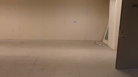
We also conduct a collision avoidance experiment to test the real time ranging accuracy. In this experiment, 8 Crazyflie drones hover at the height 70cm in a compact area less than 3m by 3m. While a ninth Crazyflie drone is manually controlled to fly into this area. Thanks to the swarm ranging protocol, a drone detects the coming drone by ranging distance, and lower its height to avoid collision once the distance is small than a threshold, 30cm.
cd crazyflie-firmware/src/deck/drivers/src/swarming
Then build the firmware.
make clean
make
Flash the cf2.bin.
cfloader flash path/to/cf2.bin stm32-fw
Open the client, connect to one of the drones and add log variables. (We use radio channel as the address of the drone) Our swarm ranging protocol allows the drones to ranging with multiple targets at the same time. The following shows that our swarm ranging protocol works very efficiently.
Summary
We designed a ranging protocol specially for dense and dynamic swarms. Only a single type of message is used in our protocol which is broadcasted periodically. Timestamps are carried by this message so that the distance can be calculated. Also, we implemented our proposed ranging protocol on Crazyflie drones. Experiment shows that our protocol works very efficiently.
For quite a while now, I have been very interested in the Rust programming language and since Jonas joined us we are two rust-enthusiast at Bitcraze. Rust is a relatively recent programming language that aims at being safe, performant and productive. It is a system programming language in the sense that it compiles to machine code with minimal runtime. It prevents a lot of bugs at compile time and it provides great mechanisms for abstraction that makes it sometime feels as high level as languages like Python.
I have been interested in applying my love for Rust at Bitcraze, mostly during fun Fridays. There is two area that I have mainly explored so far: Putting Rust in embedded systems to replace pieces of C, having such a high-level-looking language in embedded is refreshing, and re-writing the Crazyflie lib on PC in rust to make it more performant and more portable. In this blog post I will talk about the later, I keep embedded rust for a future blog post :).
Re-implementing Crazyflie lib
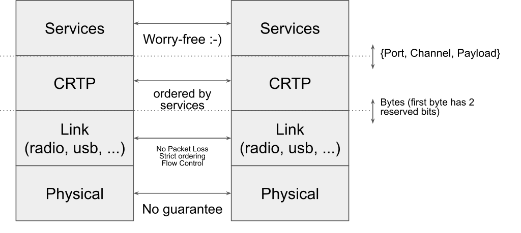
To re-implement the Crazyflie lib, the easiest it to follow the way the communication stack is currently setup, more information can be found on Crtp in a pevious blog post about the Crazyflie radio communication and the communication reliability.
Since I am currently focusing on implementing communication using the Crazyradio dongle, I have separated the implementation in the following modules (A crate is the Rust version of a library):
This organization is very similar to the layering that we have in the python crazyflie-lib, the difference being that in the Crazyflie lib all the layers are distributed in the same Python package.
At the time this blog post is written, the Crazyradio crate is full featured. The link is in a good shape and even has a python binding. The Crazyflie lib however is still very much work in progress. I started by implementing the ‘hard’ parts like log and param but more directly useful part like set-points (what is needed to actually fly the Crazyflie) are not implemented yet.
Compiling to the web: Wasm
One of the nice property of Rust is that compiling to different platform is generally easy and seemless. For instance, all the crates talked about previously will compile and run on Windows/Mac/Linux without any modification including the Python binding using only the standard Rust install. One of the Rust supported platform is a bit more special and interesting compared to the other though: WebAssembly.
WebAssembly is a virtual machine that is designed to be targeted by system programming language like C/C++ and Rust. It can be used in standalone (a bit like the Java VM) as well as in a web browses. All modern web browser supports and can run WebAssembly code. WebAssembly can be called from JavaScript.
The WebAssembly in the web is unfortunately not as easy to target as the native Windows/Mac/Linux: WebAssembly does not support threading yet, USB access needs to be handled via WebUSB and since we run in a web browser from JavaScript we have to follow some rules inherited from it. The most important being that the program can never block (ie. std::sync::Mutex shall not be used, I have tried ….).
I made two major modification to my existing code in order to make it possible to run in a web browser:
crazyflie-link and crazyflie-lib have been re-implemented using Rust async/await. This means that there is no thread needed and Rust async/await interfaces almost seamlessly with Javascript’s promises. The link and lib still compile and work well on native platforms.
I have created a new crate named crazyradio-webusb (not uploaded yet at the release of this post) that exposes the same API as the crazyradio crates but using WebUSB to communicate with the Crazyradio.
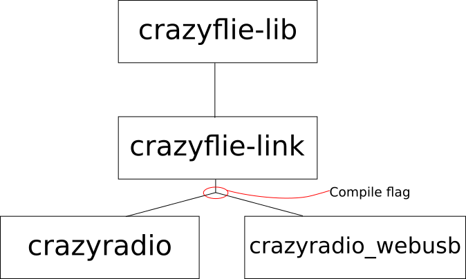
To support the web, the relationship between the crates becomes as follow:
The main goal is to keep the crazyflie-lib and crazyflie-link unmodified. Support for the Crazyradio in native and on the web is handled by two crates that exposes the same async API. The crate used is chosen by a compile flag (called Features in the rust world). This architecture could easily be expanded to other platform like Android or iOS.
Status, demo and future work
I have started getting something working end-to-end in the browser. The lib currently only implements Crazyflie Param and the Log TOC so the current demo scans for Crazyflie, connects the first found Crazyflie and prints the list of parameters with the parameters type and values. It can be found on Crazyflie web client test server. This doesn’t do anything useful now, but I am going to update this server when I make progress, so feel free to visit it in the future :).
Note that WebUSB is currently only implemented by Chromium-based browser so Chrome, Chromium and recent Edge. On Windows you need to install the WinUSB driver for the Crazyradio using Zadig. On Linux/Mac/Android it should work out of the box.
The source code for the Web Client is not pushed on Github yet, once it is, it will be named crazyflie-client-web. It is currently mostly implemented in Rust and it will likely mostly be Rust since it is much easier to stick with one (great!) language. One of the plan is to make a javascript API and to push it on NPM, this will then become a Crazyflie lib usable by anyone on the web from JavaScript (or a bit better, TypeScript …).
My goal for now is to implement a clone of the Crazyflie Client flight control tab on the web. This would provide a nice way to get started with the Crazyflie without having to install anything.
This week we have a guest blog post from Wenda Zhao, Ph.D. candidate at the Dynamic System Lab (with Prof. Angela Schoellig), University of Toronto Institute for Aerospace Studies (UTIAS). Enjoy!
Accurate indoor localization is a crucial enabling capability for indoor robotics. Small and computationally-constrained indoor mobile robots have led researchers to pursue localization methods leveraging low-power and lightweight sensors. Ultra-wideband (UWB) technology, in particular, has been shown to provide sub-meter accurate, high-frequency, obstacle-penetrating ranging measurements that are robust to radio-frequency interference, using tiny integrated circuits. UWB chips have already been included in the latest generations of smartphones (iPhone 12, Samsung Galaxy S21, etc.) with the expectation that they will support faster data transfer and accurate indoor positioning, even in cluttered environments.
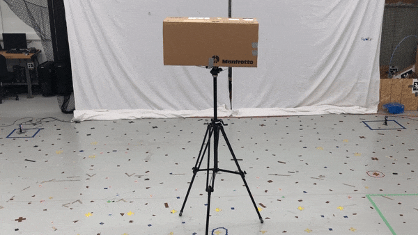
A Crazyflie with an IMU and UWB tag flies through a cardboard tunnel. A vision-based motion capture system would not be able to achieve this due to the occlusion.
In our lab, we show that a Crazyflie nano-quadcopter can stably fly through a cardboard tunnel with only an IMU and UWB tag, from Bitcraze’s Loco Positioning System (LPS), for state estimation. However, it is challenging to achieve a reliable localization performance as we show above. Many factors can reduce the accuracy and reliability of UWB localization, for either two-way ranging (TWR) or time-difference-of-arrival (TDOA) measurements. Non-line-of-sight (NLOS) and multi-path radio propagation can lead to erroneous, spurious measurements (so-called outliers). Even line-of-sight (LOS) UWB measurements exhibit error patterns (i.e., bias), which are typically caused by the UWB antenna’s radiation characteristics. In our recent work, we present an M-estimation-based robust Kalman filter to reduce the influence of outliers and achieve robust UWB localization. We contributed an implementation of the robust Kalman filter for both TWR and TDOA (PR #707 and #745) to Bitcraze’s crazyflie-firmware open-source project.
Methodology
The conventional Kalman filter, a primary sensor fusion mechanism, is sensitive to measurement outliers due to its minimum mean-square-error (MMSE) criterion. To achieve robust estimation, it is critical to properly handle measurement outliers. We implement a robust M-estimation method to address this problem. Instead of using a least-squares, maximum-likelihood cost function, we use a robust cost function to downweigh the influence of outlier measurements [1]. Compared to Random Sample Consensus (RANSAC) approaches, our method can handle sparse UWB measurements, which are often a challenge for RANSAC.
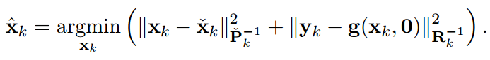
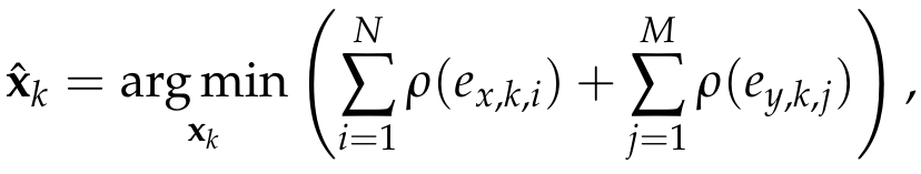
From the Bayesian maximum-a-posteriori perspective, the Kalman filter state estimation framework can be derived by solving the following minimization problem:
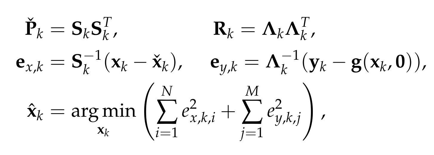
Therein, xk and yk are the system state and measurements at timestep k. Pk and Rk denote the prior covariance and measurement covariance, respectively. The prior and posteriori estimates are denoted as xk check and xk hat and the measurement function without noise is indicated as g(xk,0). Through Cholesky factorization of Pk and Rk, the original optimization problem is equivalent to
where ex,k,i and ey,k,j are the elements of ex,k and ey,k. To reduce the influence of outliers, we incorporate a robust cost function into the Kalman filter framework as follows:
where rho() could be any robust function (G-M, SC-DCS, Huber, Cauchy, etc.[2]).
By introducing a weight function for the process and measurement uncertainties—with e as input—we can translate the optimization problem into an Iteratively Reweighted Least Squares (IRLS) problem. Then, the optimal posteriori estimate can be computed through iteratively solving the least-squares problem using the robust weights computed from the previous solution. In our implementation, we use the G-M robust cost function and the maximum iteration is set to be two for computational reasons. For further details about the robust Kalman filter, readers are referred to our ICRA/RA-L paper and the onboard firmware (mm_tdoa_robust.c and mm_distance_robust.c).
Performance
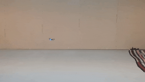
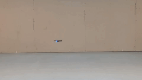
We demonstrate the effectiveness of the robust Kalman filter on-board a Crazyflie 2.1. The Crazyflie is equipped with an IMU and an LPS UWB tag (in TDOA2 mode). With the conventional onboard extended Kalman filter, the drone is affected by measurement outliers and jumps around significantly while trying to hover. In contrast, with the robust Kalman filter, the drone shows a more reliable localization performance.
Conventional extended Kalman filter
M-estimation-based robust Kalman filter
Quadcopter is commanded to hover. UWB TDOA-based localization performance of standard method on-board a Crazyflie 2.1 quadcopter (left) and the proposed robust Kalman filter (right).
The robust Kalman filter implementations for UWB TWR and TDOA localization have been included in the crazyflie-firmware master branch as of March 2021 (2021.03 release). This functionality can be turned on by setting a parameter (robustTwr or robustTdoa) in estimator_kalman.c. We encourage LPS users to check out this new functionality.
As we mentioned above, off-the-shelf, low-cost UWB modules also exhibit distinctive and reproducible bias patterns. In our recent work, we devised experiments using the LPS UWB modules and showed that the systematic biases have a strong relationship with the pose of the tag and the anchors as they result from the UWB radio doughnut-shaped antenna pattern. A pre-trained neural network is used to approximate the systematic biases. By combining bias compensation with the robust Kalman filter, we obtain a lightweight, learning-enhanced localization framework that achieves accurate and reliable UWB indoor positioning. We show that our approach runs in real-time and in closed-loop on-board a Crazyflie nano-quadcopter yielding enhanced localization performance for autonomous trajectory tracking. The dataset for the systematic biases in UWB TDOA measurements is available on our Open-source Code & Dataset webpage. We are also currently working on a more comprehensive dataset with IMU, UWB, and optical flow measurements and again based on the Crazyflie platform. So stay tuned!
Reference
[1] L. Chang, K. Li, and B. Hu, “Huber’s M-estimation-based process uncertainty robust filter for integrated INS/GPS,” IEEE Sensors Journal, 2015, vol. 15, no. 6, pp. 3367–3374.
[2] K. MacTavish and T. D. Barfoot, “At all costs: A comparison of robust cost functions for camera correspondence outliers,” in IEEE Conference on Computer and Robot Vision (CRV). 2015, pp. 62–69.
Feel free to contact us if you have any questions or suggestions: wenda.zhao@robotics.utias.utoronto.ca.
Please cite this as:
<code>@ARTICLE{Zhao2021Learningbased,
author={W. {Zhao} and J. {Panerati} and A. P. {Schoellig}},
title={Learning-based Bias Correction for Time Difference of Arrival Ultra-wideband Localization of Resource-constrained Mobile Robots},
journal={IEEE Robotics and Automation Letters},
volume={6},
number={2},
pages={3639-3646},
year={2021},
publisher={IEEE}
doi={10.1109/LRA.2021.3064199}}
</code>