Background
In the past couple of weeks we have been busy trying to improve the development interface of the Crazyflie. We want to make developing with and for the platform a more pleasant experience.
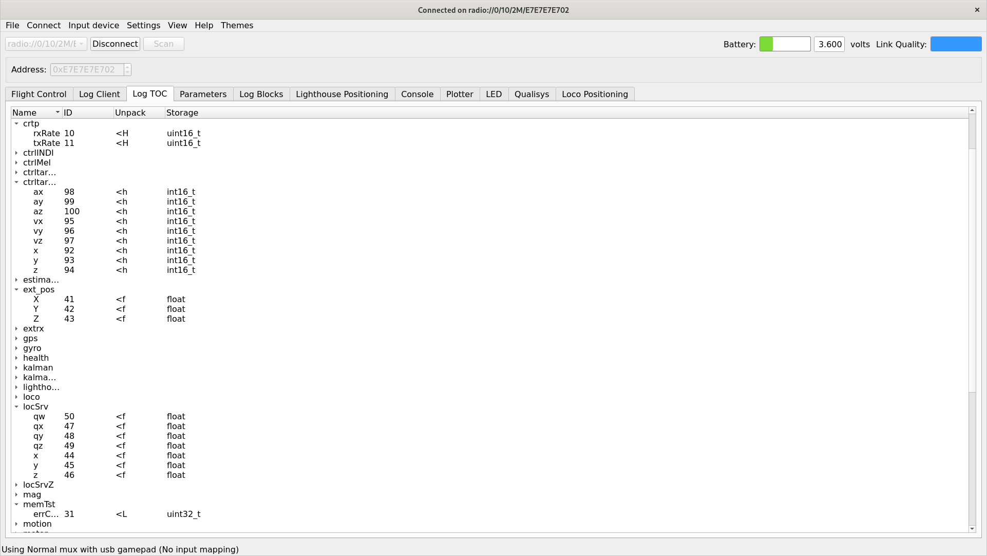
We have started looking at the logging- and parameter framework and how to improve it for our users. The aim of this framework is to easily be able to log data from the Crazyflie and to set variables during runtime. Your application can use them to control the behavior of the platform or to receive data about what it is currently up to. As of today, in the firmware there are 227 parameters and 467 logging variables defined.
These logging variables and parameters have been added to the Crazyflie firmware over the course of years. Some are critical infrastructure, needed to be able to write proper applications that interface with the platform. Some are duplicates or were added as debug years ago. Others have in some way outlived their usefulness as the firmware and functionality has moved on. The problem is that we have no way of conveying this information to our users and this is what we are trying to rectify.
An attempt of stability
We are currently reviewing all of our logging variables and parameters in an attempt to make the situation clearer for our users … and ourselves. We are adding documentation to make the purpose of each individual parameters and logging variables more clear. And we are also dividing them up into two categories: core and non-core.
If a parameter or logging variable is marked as core in the firmware that constitutes a promise that we will try very hard to not remove, rename or in any other way change the behavior of it. The idea is that this variable or parameter can be used in applications without any fear or doubt about it going away.
If a variable or parameter is non-core it does not mean that it is marked for removal. But, it could mean that we need more time to make sure that it is the proper interface for the platform. It means that it could change in some way or in some cases be removed in later firmware releases.
The reason for doing this is twofold: we want to make the Crazyflie interface clearer for our users and we want something that we feel we can maintain and keep an up-to-date documentation of.
What is the result?
We have introduced a pair of new macros to the firmware, LOG_ADD_CORE and PARAM_ADD_CORE which can be used to mark a parameter or variable as core. When using these we also mandate that there should be a Doxygen comment attached to the macro.
Below is an example from the barometer log group, showing the style of documentation expected and how to mark a logging variable as core. Parameters gets treated in the same way.
/**
 * Log group for the barometer
 */
LOG_GROUP_START(baro)

/**
 * @brief Altitude above Sea Level [m]
 */
LOG_ADD_CORE(LOG_FLOAT, asl, &sensorData.baro.asl)

/**
 * @brief Temperature [degrees Celsius]
 */
LOG_ADD(LOG_FLOAT, temp, &sensorData.baro.temperature)

/**
 * @brief Air pressure [mbar]
 */
LOG_ADD_CORE(LOG_FLOAT, pressure, &sensorData.baro.pressure)

LOG_GROUP_STOP(baro)
We have also added a script In the firmware repository: elf_sanity.py. The script will return data about parameters and logging variables that it is included in a firmware elf. This can be used to count the number of core parameters. If we point it to a newly built Crazyflie elf, after we’ve done our initial review pass of the parameters and variables, we get the result below.
$ python3 tools/build/elf_sanity.py --core cf2.elf
101 parameters and 78 log vars in elf
To produce a list of the parameters and variables you can add the --list-params and --list-logs options to the script.
What is the next step?
Once we have finished our review of the parameters and logging variables we will explore different ways of making the documentation of them available in a clear and accessible way. And we will come up with a scheme for making changes to the set of parameters and variables. Once this is all finished you can expect an update from us.
The end goal of our efforts is making developing for the Crazyflie a smoother process, and we would love to hear from you. What is confusing? What are your pain points? Let us know! So we can do better.