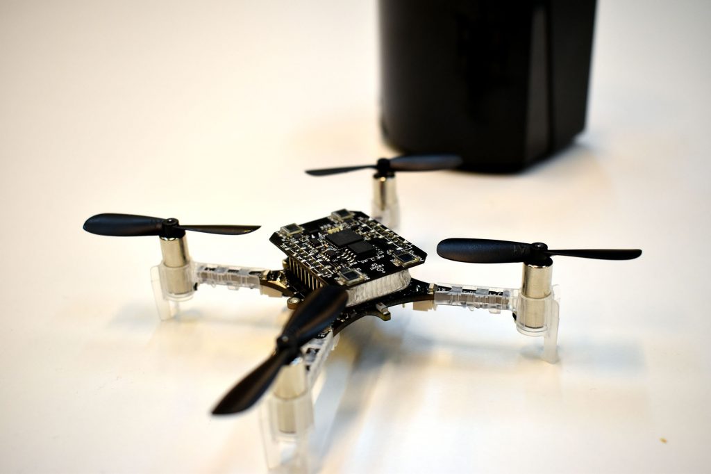
I started working with the Crazyflie 2.0 in 2015. I was interested in learning how to program a quadcopter, and the open-source nature of the Crazyflie’s hardware and software was the perfect starting point.
Shortly after, I discovered the world of FPV and the thrill of flying with a bird’s eye view. My journey progressed from rubber-banding an all-in-one camera/VTX to my Crazyflie, to building a 250mm racing quad (via the BigQuad deck), and into the world of Betaflight (including bringing Betaflight support to the Crazyflie hardware).
-
-
FPV for Beginners ;)
-
-
BigQuad Build
Naturally, the announcement of the Bolt (then known as the RZR) piqued my interest, and the folks at Bitcraze graciously allowed me early hands-on with the product.
This post details my progress towards building out a FPV-style drone on top of the Crazyflie Bolt.
Component List
The FPV community has come a long way since 2015. What once was a very complicated process is now well documented and similar to building a PC (well, with some soldering). For latest details on the specifics of building FPV drones, I recommend resources such as Joshua Bardwell or the r/Multicopter subreddit.
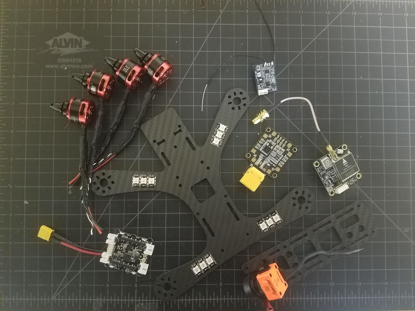
Turns out I had enough components lying around for a 4-inch (propeller diameter) build based on 3S (3 cell) LiPo batteries. Again, there’s nothing special about these parts (in fact they’re all out of date). Take this list as a guide, and do your own research.

- PDB (Power Distribution Board): This is a circuit board that produces regulated voltages from an unregulated LiPo battery. The Bolt has built-in regulators but is only rated up to an 8A current draw per motor. My 4 inch propellers will certainly draw more than 8A, and so an external PDB is required (plus having dedicated 12V and 5V supplies is nice for peripherals).
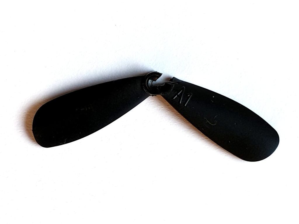
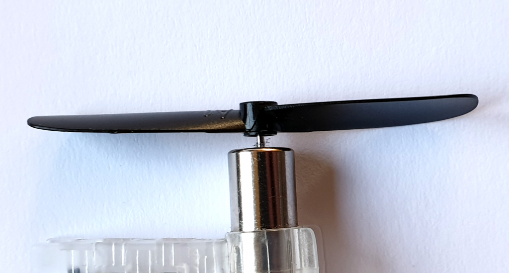
- 4x DYS 1806 Brushless Motors: Brushless motors use magnetic pulses to rotate a motor bell (distinct from brushed motors found on the regular Crazyflie).
- 4x DYS 20A BLHeli_S ESCs (Electronic Speed Controller): This is a piece of circuitry that accepts a logic-level control signal and applies direct battery power to motor coils to make a brushless motor spin. They have to be rated for the current draw expected by the battery+propeller combination.
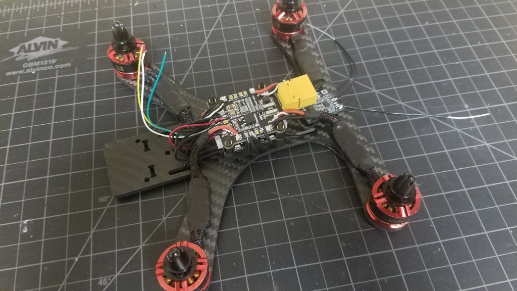
- Tweaker (by Shendrones) Frame: I’ve been wanting to build a quad around this frame, and the large square hole is interesting for the Bolt (more on that later). One thing to keep in mind is this is an ‘H’ style frame. That is, it’s longer than it is wide, so flight will not be perfectly symmetrical. If you’re interested in building a larger Crazyflie and not so interested in FPV, you’ll definitely want a symmetrical ‘X’ style frame.
- WS2812B addressable LEDs: LEDs are proven to make things better. It’s science.
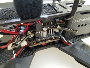
- Camera + VTX: For a full FPV setup, you’ll need a camera and a video transmitter. For the most part these run completely independently of the flight controller and so I’ll omit them from this article — what I’ve shown in the picture above is horribly out of date anyway.
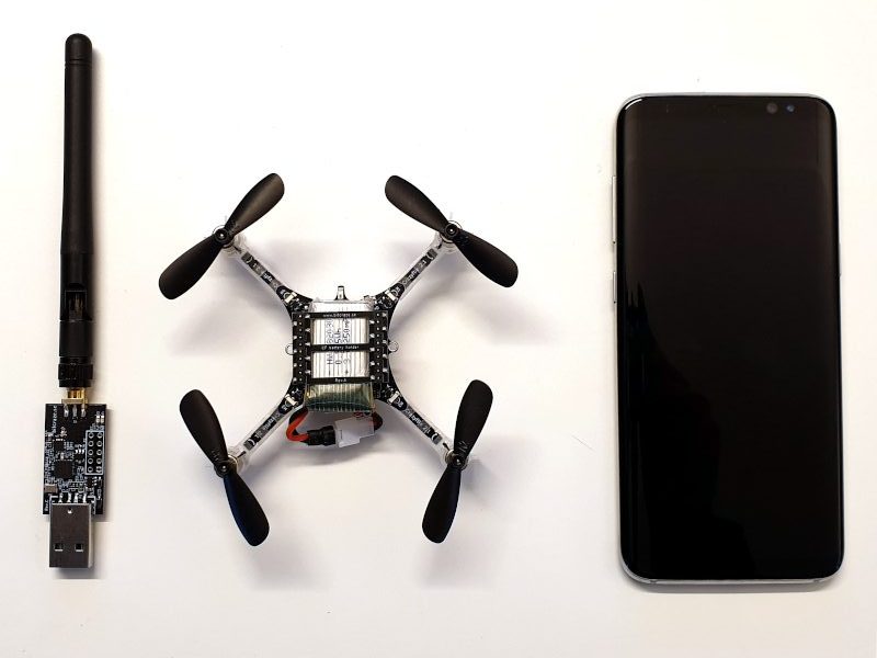
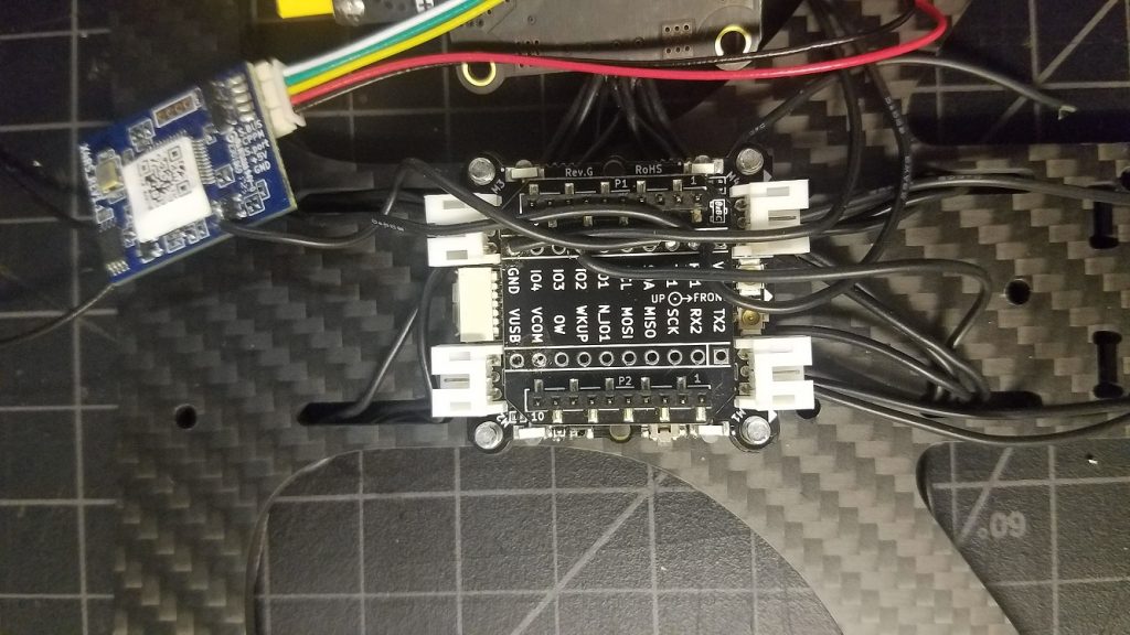
- RX: Radio receiver. For longer range flights and reduced latency it may be a good idea to use an external radio and UART-based receiver with diversity antennas. However, some specific work went in to the Bolt’s antenna design, so I’ll be sticking with the on-board NRF51 and external antenna.
- Flight Controller: The Crazyflie Bolt!
The Build
Again, there are hundreds of fantastic guides on the web that detail how to build an FPV quadcopter. Instead of trying to create another, here are some notes specific to my Bolt build.
Expansion Decks
Since the Bolt is pin compatible with the Crazyflie, I thought it would be interesting to try and take advantage of a couple existing Crazyflie expansion decks in my build: The
LED Ring Deck, the
Flow Deck v2, and the
Micro SD Card Deck.
The LED Ring Deck
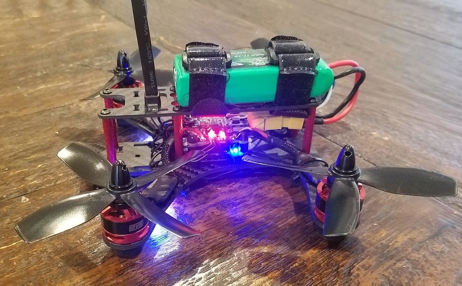
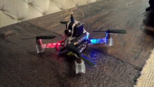
The LEDs were the most hands-on feature to enable. Rather than simply attaching the LED ring inside the frame, I mounted a series of WS2812B lights to the underside of my frame’s arms. The LED Ring Deck consists of 12 LEDs connected in series — so I put three LEDs on each arm of the frame and wired them up in a daisy-chain.
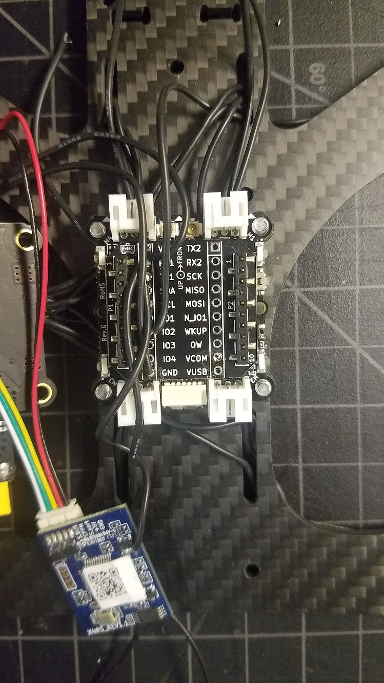
Finally, I soldered the lead to IO_2 (the same that’s used by the LED Ring Deck) on a Breakout Deck.
Since this isn’t the official LED Ring Deck, there’s no OW memory ID. The deck must be force-enabled by specifying a compile flag in your tools/build/make/config.mk file:
CFLAGS += -DDECK_FORCE=bcLedRing
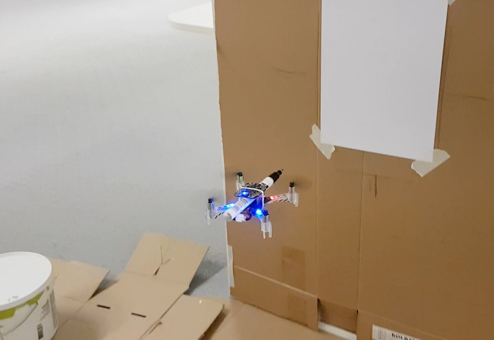
With the custom firmware, the under-arm LEDs work just like the LED Ring Deck (other than the lack of front-facing LEDs).
Micro SD Card Deck
Most popular flight controllers feature flash storage or SD card slots for data logging. The FPV community uses storage to log sensor data for PID tuning and debugging. Naturally, this deck is a good fit on my Bolt build, and requires no additional modification.
Flow Deck (v2)
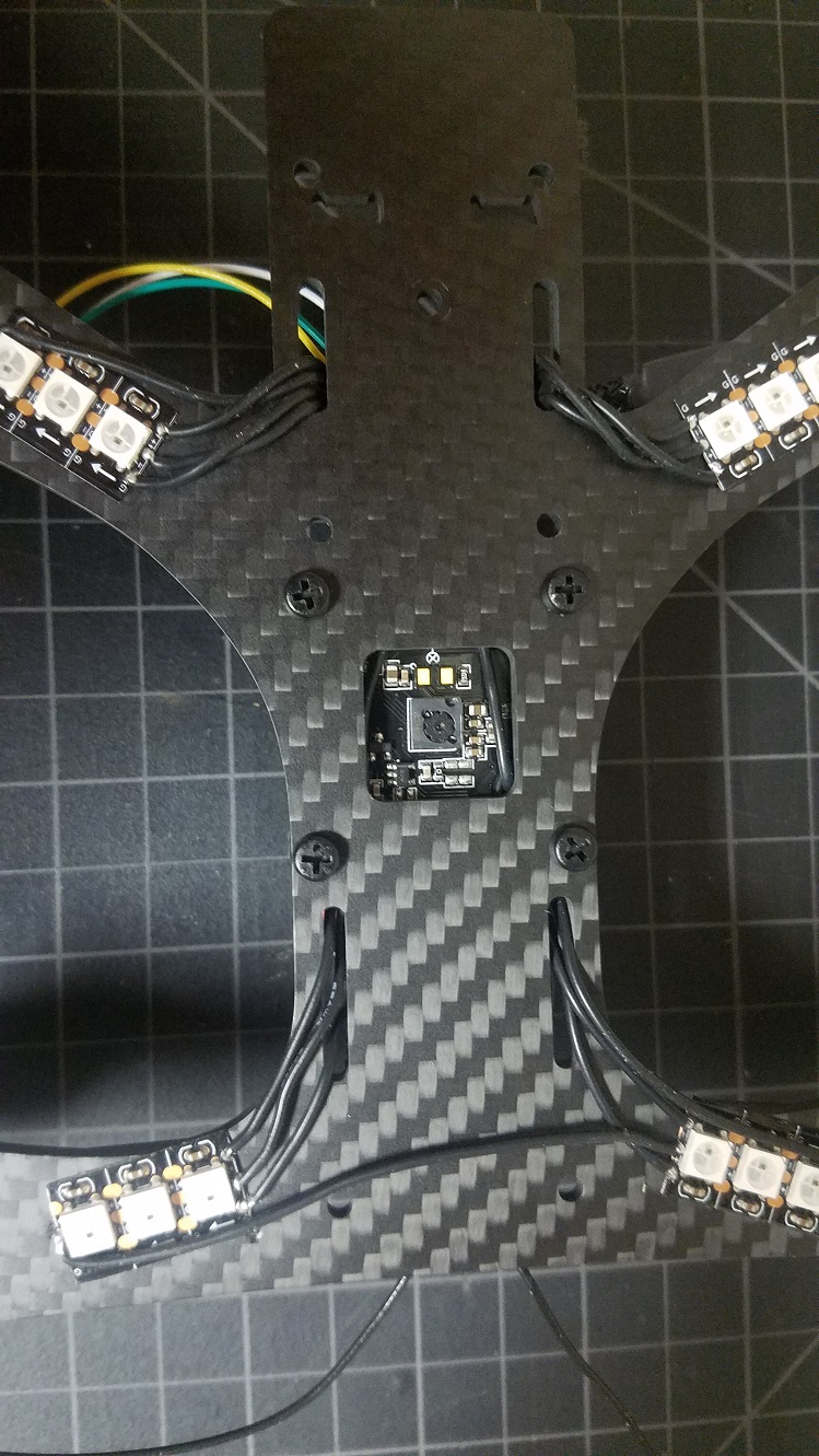
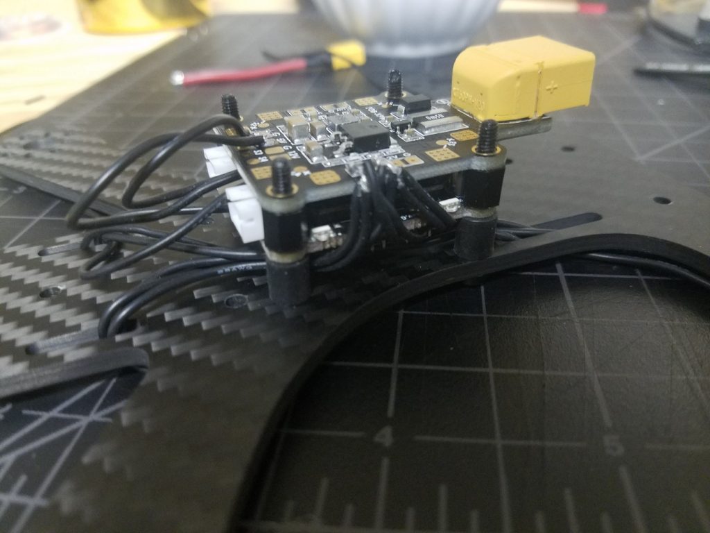
Remember my interest in the square cutout on my frame of choice? That, and my unorthodox choice to mount the Bolt board below my PDB, means I can theoretically use the bottom-attached Flow Deck to achieve some lateral stabilization while close to the ground. In theory, the VL53L1x ranger should work outdoors thanks to its usage of 940nm light as opposed to 850nm.
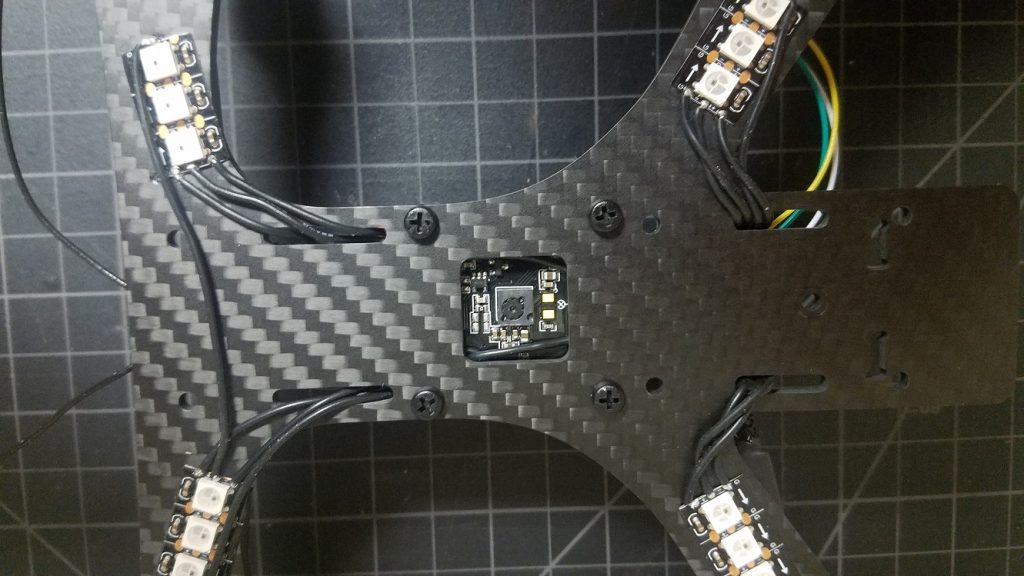
Note: This photo also shows the daisy chain wire connecting banks of LEDs in series
Other Build Tips
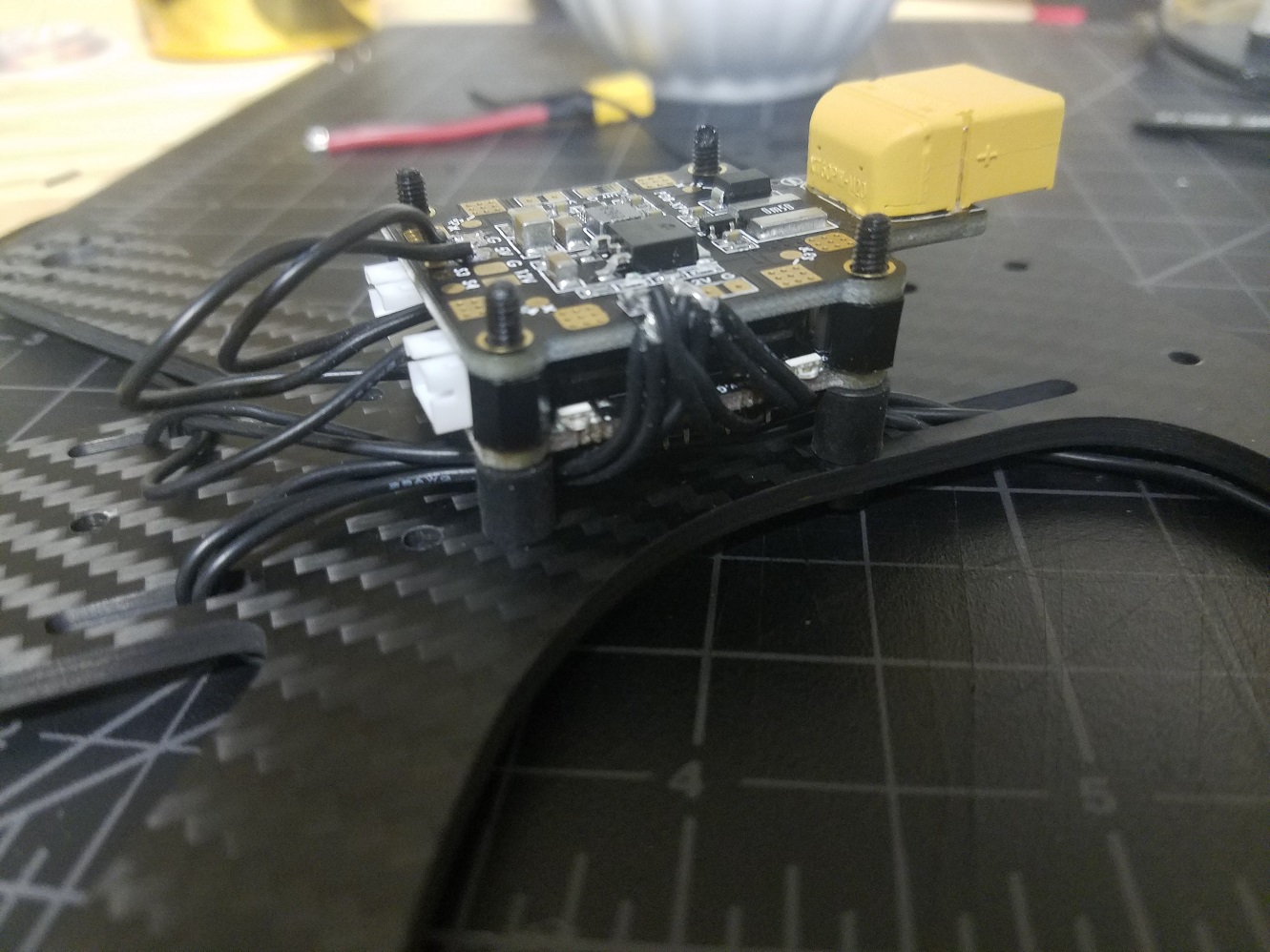
- It’s good practice to soft mount flight controllers to minimize transferring motor/prop vibrations into the IMU. I used these to isolate the flight controller from the frame — not perfect, but better than a rigid mount.
- The receiver antenna must be mounted clear of the carbon fiber frame and electronics. I like to use a heavy duty zip tie and attach the antenna with heat shrink.
- The Bolt can be powered from a 5v regulator on your PDB, but if you want to take advantage of the VBat sensor it should be powered from the raw battery leads instead. However, most ESCs support active breaking (ability to slow/stop the propellers on demand). Active breaking is known to produce a lot of back-voltage, which can damage some circuits. To be safe, since I’m using a 3S battery (12.6V when fully charged, 11.1V when depleted) I chose to power the Bolt off a regulated 12V supply from my PDB. This way, the PDB’s regulator will filter out voltage spikes and help protect the Bolt. Readings won’t be accurate at the higher range, but what really matters for a voltage sensor is to know when to land.
Results
It works! There is work needed to improve flight, though:
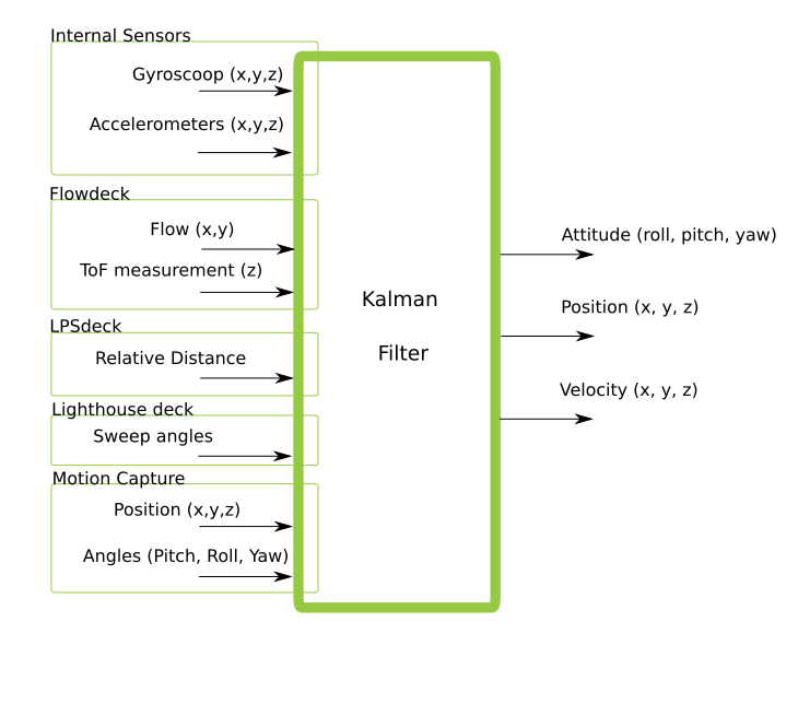
- Control tuning is required. The powerful brushless motors respond much quicker than brushed motors, and so many of the PID and/or Kalman parameters are too aggressive or just non-optimal.
- Stabilization with the Flow deck does not work — I haven’t spent much time debugging but my guess is it’s either due to the Kalman tuning, or problems with the VL53L1x depth working outdoors (which also impacts the flow measurements)
- Betaflight Support: Betaflight has no driver for the BMI088 IMU used on the Crazyflie Bolt or the Crazyflie 2.1.
- Safety Features: Brushless quads are very dangerous and can cause serious injuries. It’d be good to implement a kill-switch and a more aggressive failsafe in the firmware to prevent flyaways.
All in all, this was an enjoyable project and I’m excited to see some autonomous brushed quads coming out of the Crazyflie community!