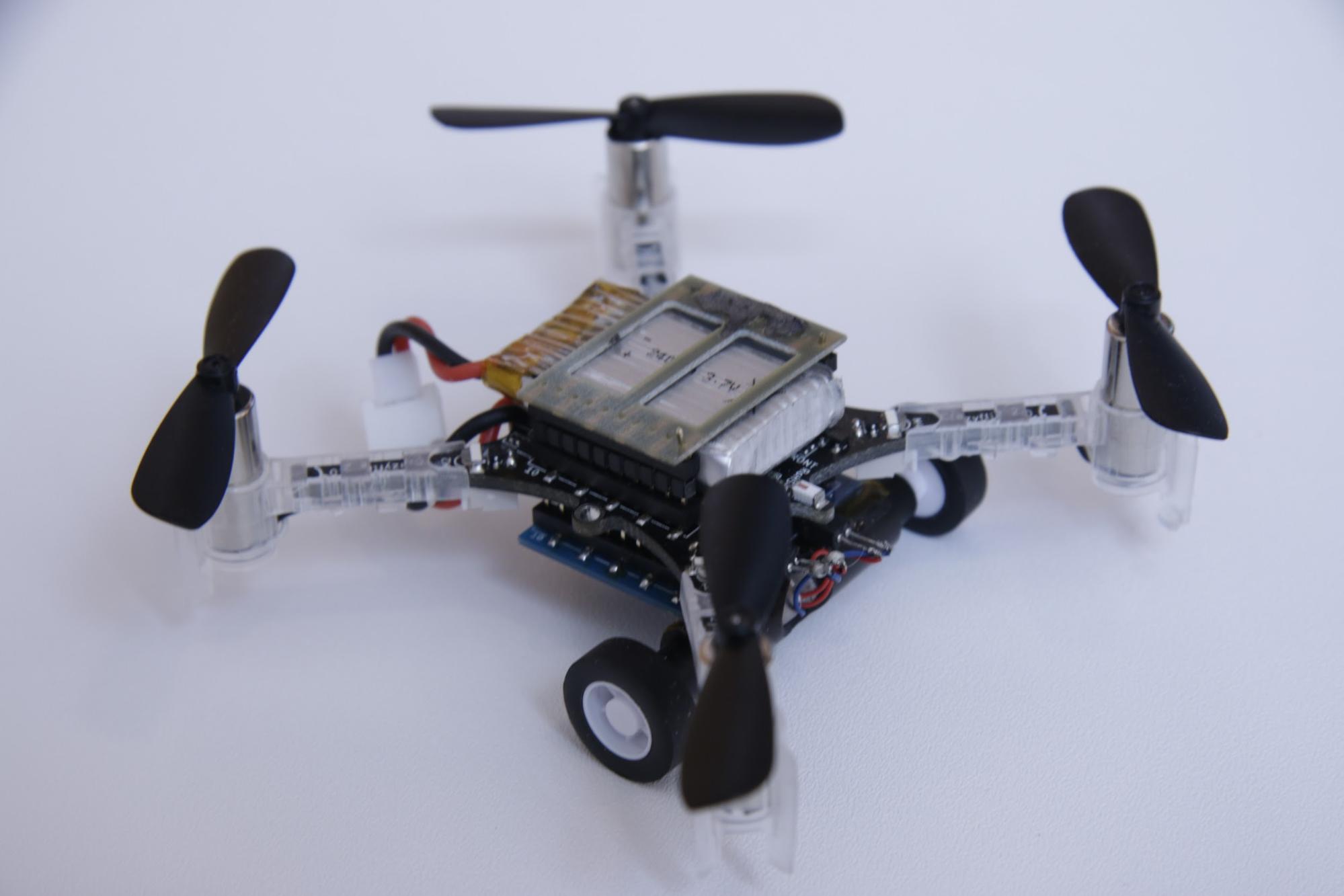
As we announced recently, the Flow deck for the Crazyflie has been released. There was a high demand the first days and we were unfortunately out of stock in the store for a short time, but now we are restocked and the deck is available again. We also got a shipment of a few production Flow decks to the office, and of course we wanted to play a bit with them to find the limits. During development of the deck we only had one or two working prototypes at a time, but now there were manny, so what could we do?
Swarm with the Flow deck
Aggressive flying
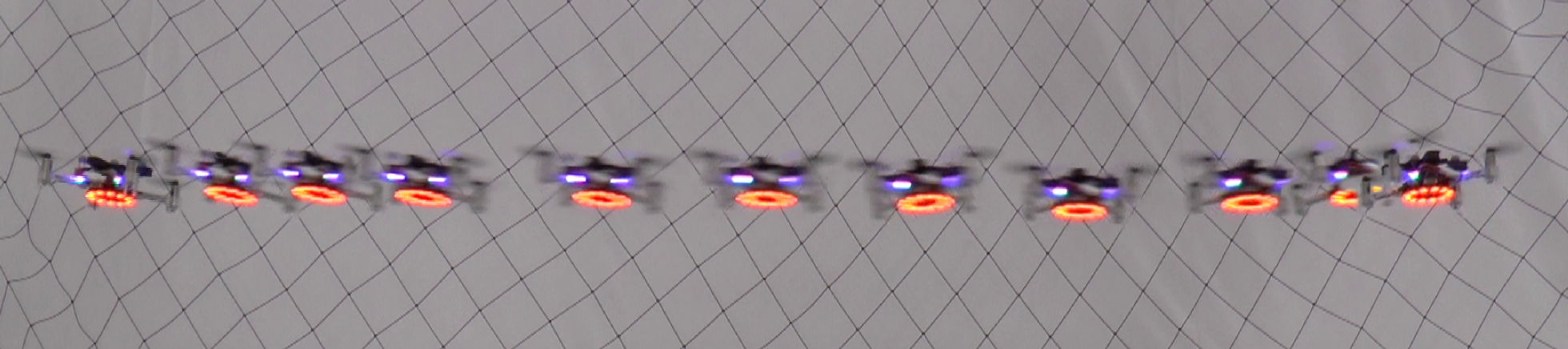
So far we have flown slowish when using the Flow deck and we know that works, but what about more aggressive manoeuvres? We modified the flowsequenceSync.py script in the examples directory of the crazyflie-lib-python library. The original script flies a figure 8 at 0.5 m/s, and we spiced it up to do 1.5 m/s instead.
It works pretty well as you can see in the video but we get a drift for every finished figure 8 and we have not really figured out yet the origin of this error. There are a number of potential error sources but it needs further investigation to be fully understod.
Flying one Crazyflie above another
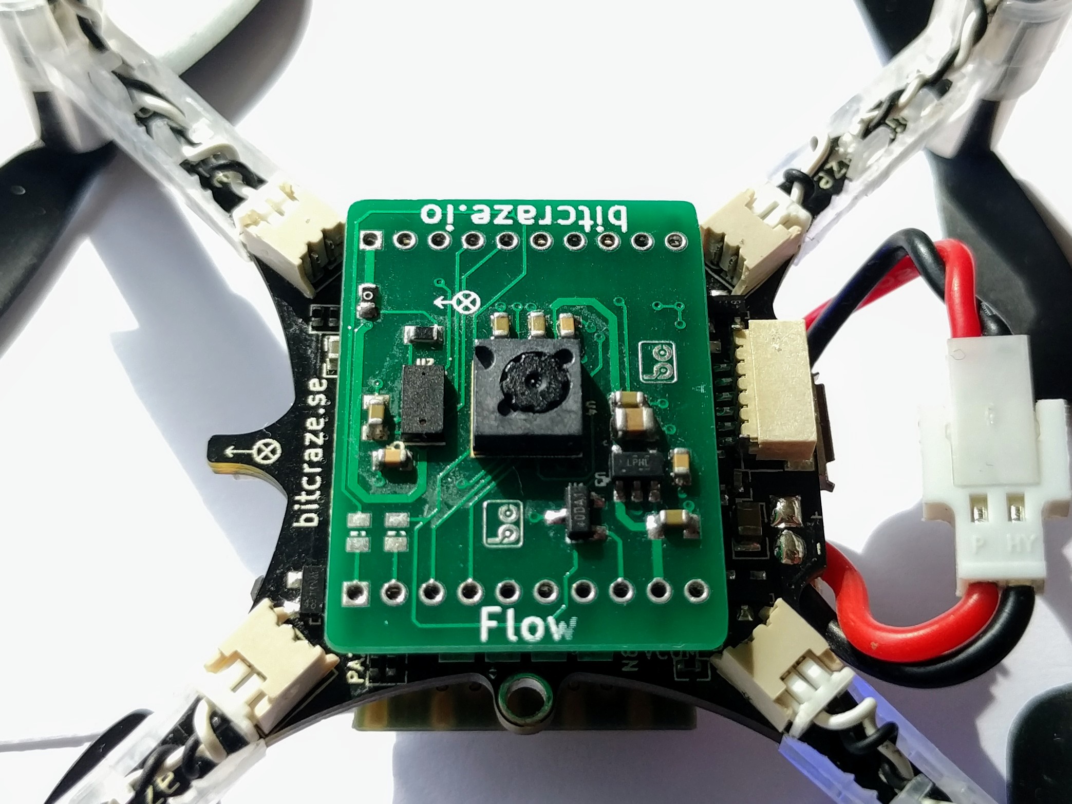
What if one Crazyflie flies above another? How will that affect the performance of the Flow deck? The optical flow sensor is in essence a camera detecting the motion of the floor, a Crazyflie passing through the field of view could potentially confuse the system.
We set up two Crazyflies to fly on a straight line in opposite directions, one 0.5 m above the other. The result was that the top Crazyflie was almost not affected at all when the other passed under it, just a small jerk. The lower one on the other hand, passed through the turbulence of the top one and this caused it to swing quite a lot, though it managed to more or less continued in the correct direction it was decidedly out of track. As expected, flying above another Crazyflie is not a good idea, at least not too close.
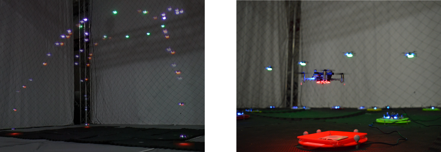
Flying a swarm with the Flow deck
When flying with the Flow deck all navigation is based on dead reckoning from the starting position, is it possible to fly a swarm using this technique? We thought that by putting the Crazyflies in well known starting positions/orientations and feed them trajectories that do not cross (or pass over each other) it should be possible. The start turned out to be critical as the system is a bit shaky at altitudes under 10 cm when the sensors on the Flow deck are not working very well yet. Sometimes the Crazyflie moves slightly during take-off and this can be a showstopper if it rotates a bit for instance, as the trajectory also will be rotated. It worked pretty well in most cases but sometimes a restart was required.
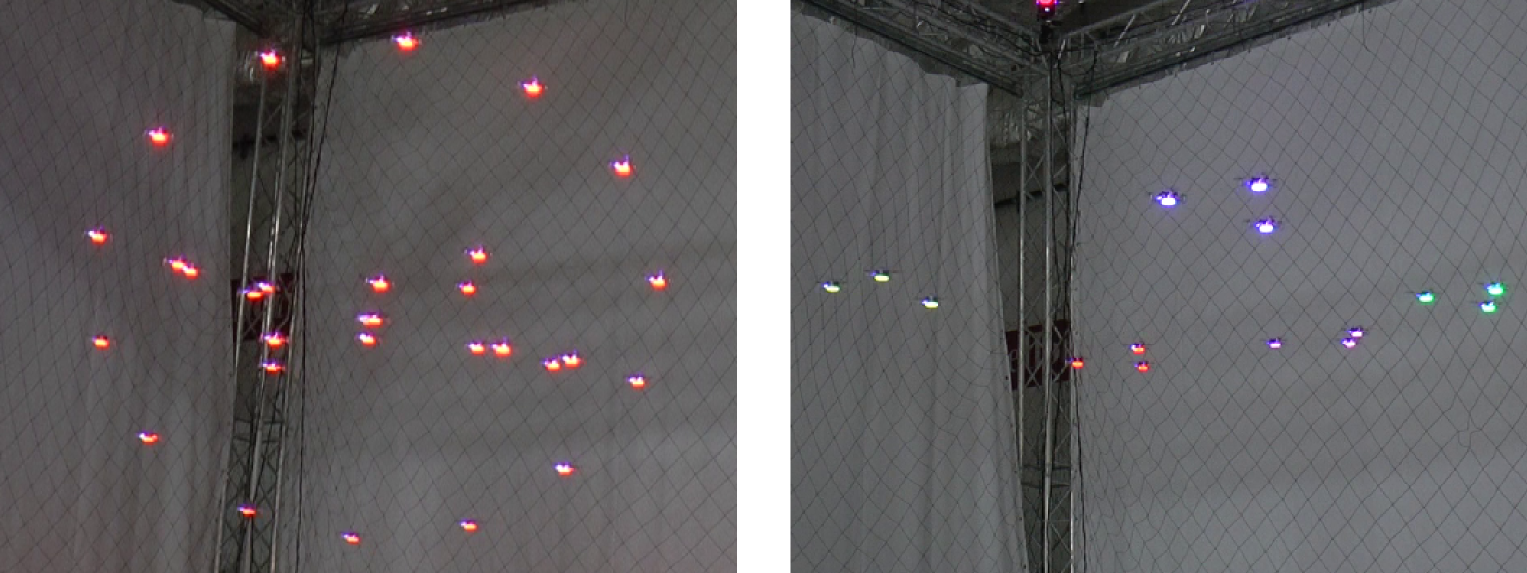
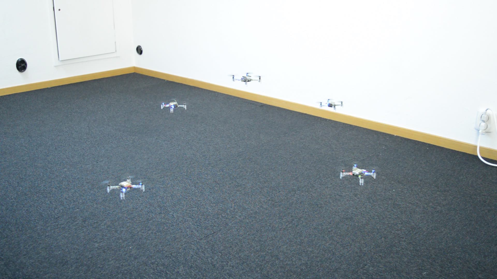
We were inspired by the Crazyswarm from USC and decided to fly 5 Crazyflies with one in the center and the other 4 spinning around it. Note the center Crazyflie turning but staying on the spot.
We used the Swarm class in the python library to control the 5 Crazyflies. The code used to connect to the Crazyflies one by one which takes quite some time, we changed it to a parallel connect while we were at it and got a significant speed up.
The code for the swarm is available as an example in the python library.
It is a lot of fun playing with the Flow deck and scripting flights. I know it might be silly, but we laugh the hardest when we fail and crash, the more spectacular the crash the more happiness!
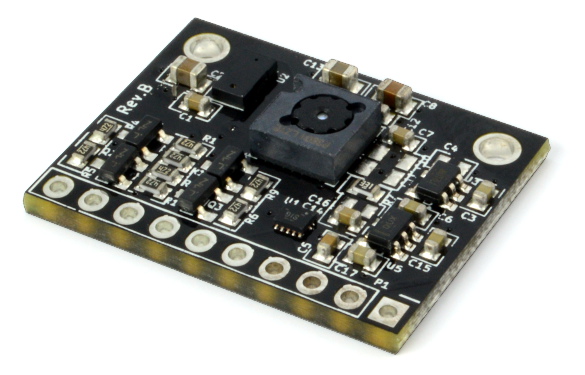
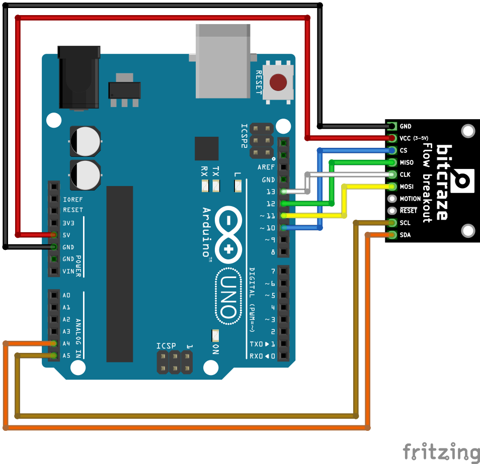
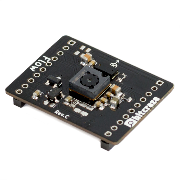
The Flow breakout
For other robotics projects that don’t use the Crazyflie, remember that the same functionality as the Flow deck delivers soon will be available in the Flow breakout board. It is compatible with Arduino and other hosts.