In order for users to be able to pilot the Crazyflie from platforms without a graphical user interface there’s now a headless client in the repository named cfheadless. It’s intended to be run the command-line and is still under development, but working.
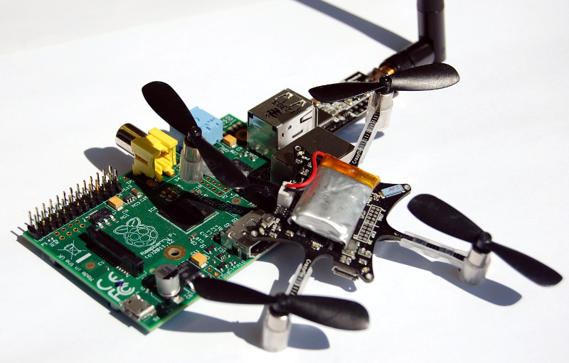
The main reason it was made in the first place was to enable flying from the Raspberry Pi. The QT interface was very sluggish and it required all the QT dependencies to be installed. So the cfheadless client doesn’t depend on QT and doesn’t have a graphical user interface at all. For users to quickly get something working with the Raspberry Pi we prepared a pre-configured SD-card image that is based on the Raspian Wheezy. We didn’t remove anything from the image, we just added the things needed to fly the Crazyflie. It works out of the box with the Crazyradio and a PS3 controller. In order to switch to anther controller you will have to connect to the Pi and edit the configuration.
To use the image you have to edit the configuration if needed and then just connect your controller, power on the Crazyflie and lastly connect the Crazyradio. The cfheadless client will now automatically start and connect to the Crazyflie.
The image can be downloaded using this torrent or via direct download. The torrent is preferred since the direct download is limited to 6 simultaneous downloads. For more information on how to use the image have a look at the wiki page and if there’s any issues or suggestions drop by the project tracker at Bitbucker and add them. If you already have a Raspian image downloaded and running and you want to be able to use it with the Crazyflie then have a look at how we made the image or the hacks page with the original instructions.