Today we have a guest blogpost by Thomas Izycki (Technische Hochschule Augsburg) and Klaus Kefferpütz (Ingolstadt Technical University of Applied Sciences, former Augsburg Technical University of Applied Sciences) talking about implementing Software-in -the-Loop for swarm simulation of the Crazyflie.
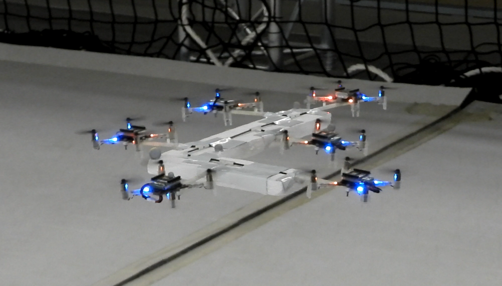
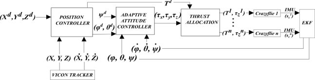
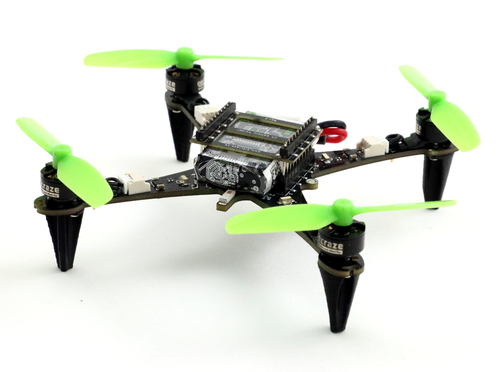
When our cooperative control lab at the Technical University of Applied Sciences Augsburg was founded a few years ago, our goal was to develop distributed algorithms for teams of UAVs. We quickly decided to use Crazyflies with the algorithms directly implemented in the firmware, thus having a platform for a truly decentralized system. Our ongoing projects focus on cooperative path planning, navigation, and communication.
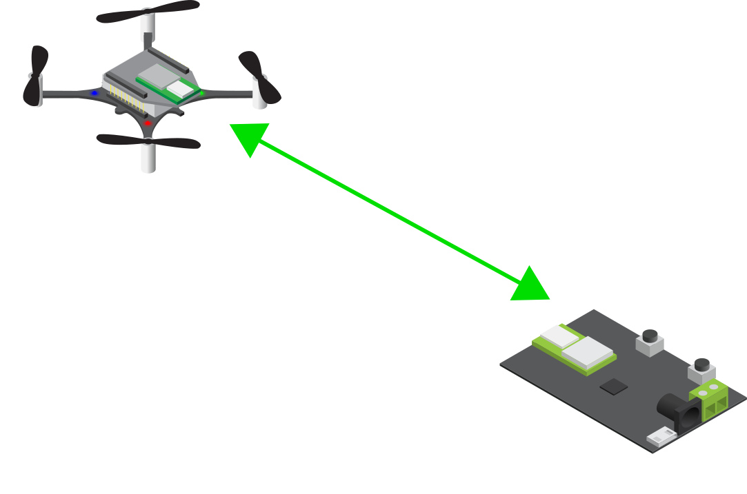
Since working with several drones at once, which have to communicate and coordinate with each other, can quickly become confusing and very time-consuming, a simulation was needed. It should preferably offer the possibility to integrate the firmware directly in the simulation environment and ideally also offer an interface to the crazyflie python API. With the relocation of our laboratory from Augsburg to the Technical University of Applied Sciences Ingolstadt, which however does not yet have a permanently established flying space, the need for a simulation environment was further increased in order to be less dependent on hardware accessibility. A look at the community and the available simulations quickly led us to the sim_cf flight simulator for the Crazyflie. A fantastic project supporting the use of the actual Crazyflie firmware in software-in-the-loop (SITL) mode and even in hardware-in-the-loop (HITL) mode on a real Crazyflie using the FreeRTOS Linux Port together with ROS and Gazebo. Unfortunately, the project has not been maintained for several years and also had no integration with the Crazyflie Python API. After a short chat with Franck Djeumou and his agreement to use the code of the original sim_cf simulation, the project was ready for an upgrade.
sim_cf2 Flight Simulator
With support for ROS coming to an end we decided to migrate the project to ROS2 and additionally support the current version of the Crazyflie firmware, which at this time is release version 2023.11. With the addition of a driver to connect the cflib to the SITL process, the same python cflib-based scripts can now be used with real Crazyflies and for use in the simulation environment. Only the corresponding driver needs to be loaded during initialization. Overall, the focus of the sim_cf2 simulation is now on using the Crazyflie python API instead of commanding the Crazyflies via ROS.
As for the Crazyflie firmware the whole build process has been fully integrated into the firmware’s KBuild build system. This also allows the use of the same code base for simulation and execution on the real Crazyflie. Depending on the configuration, the firmware is compiled for the STM32F on the Crazyflie or the host system running the SITL.
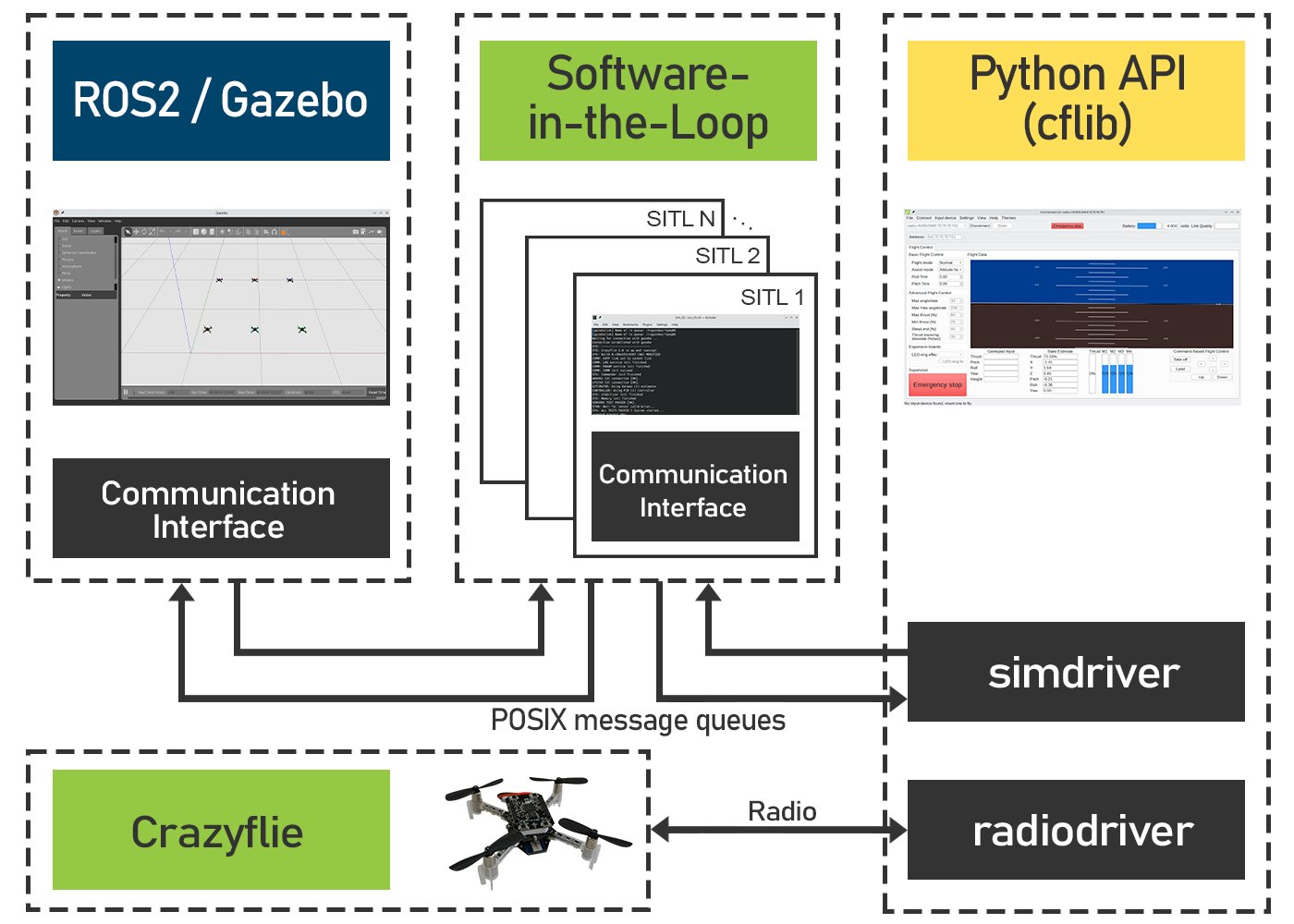
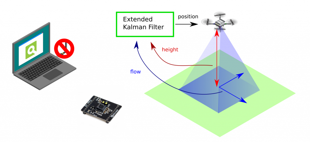
To run the simulation, the three modules must therefore be started separately. Gazebo is started using the main launch file. The number and initial pose of the simulated Crazyflies is also defined in this file. Once the firmware for the host system has been built, the desired number of SITL instances can be started using the attached script. Finally, a cflib-based script, the Crazyflie client or the multi-agent client presented below is started. With no radio dongles attached to the computer, the simulation driver is initialized automatically and a connection to the simulated Crazyflie can be established.
There are still a few open issues, including the absence of implemented decks for positioning, such as LPS and Lighthouse. Currently, the absolute position is sent from Gazebo to the SITL instance and fused in the estimator. Moreover, Gazebo requires quite a lot of computing power. We were able to run a maximum of four Crazyflies simultaneously on a relatively old laptop. However, a modern desktop CPU with multiple cores allows for simulating a significantly larger number of Crazyflies.
Multi-Agent Client
Independent of the simulation we designed a GUI for controlling and monitoring our multi-agent teams. It currently supports up to eight Crazyflies but could be upgraded for bigger teams in the future. So far it has been enough for our requirements.
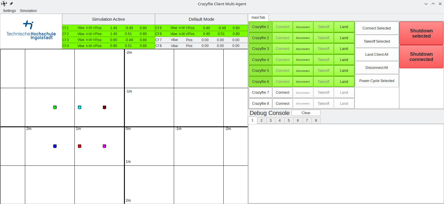
A central feature is the interactive map, which makes up about half of the gui. This is a 2D representation of the flight area with a coordinate system drawn in. Connected Crazyflies are displayed as small circles on the map and a new target position can be assigned by clicking on the map after they have been selected by their corresponding button. If required, obstacles or paths to be flown can also be drawn into the map.
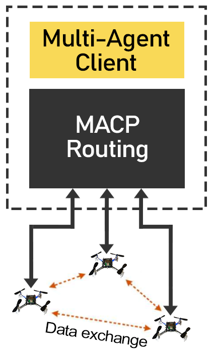
An important aspect of a truly decentralized system is peer to peer communication. It allows information to be exchanged directly between agents and ideally takes place without a central entity. Currently peer to peer communication is not available in the Crazyflie ecosystem, but is in development.
For this reason, we have implemented a workaround in our client, enabling a pseudo-decentralized communication system. This involves adding an additional layer to the Crazy RealTime Protocol (CRTP), which we named the Multi-Agent Communication Protocol (MACP). It consists of an additional packet header made of the destination ID, source ID and a port as endpoint identifier. Every ID is unique and directly derived from the Crazyflie’s address.
These MACP packets are sent via the unused CRTP port 0x9. The packet routing mechanism implemented in the client forwards the packets to their destination. It is also possible to send packets as a broadcast or to address the client directly.
On the firmware side, we have added a corresponding interface to simplify the sending and receiving of macp packets. It is analogous to the CRTP implementation and allows the registration of callback functions or queues for incoming packets on corresponding ports. It can be activated via KBuild.
At least for use in the laboratory and the development of distributed algorithms, this method has proven its worth for us.
Project
We hope that the sim_cf2 simulation can also be useful to others. The complete source code is available on GitHub. Further information concerning installation and configuration can be found in the readme files in the respective repositories.
We would also like to point out that other simulations have been created that are based on sim_cf and therefore offer similar functionality. One of these projects is CrazySim, also available on GitHub. Moreover, there are ongoing efforts to officially integrate such a software-in-the-loop simulation into the Crazyflie firmware and ecosystem.
sim_cf2:
https://github.com/CrazyflieTHI/sim_cf2
Multi-Agent Client:
https://github.com/CrazyflieTHI/crazyflie-client-multi-agent-thi
Show-and-tell post of CrazySim:
https://github.com/orgs/bitcraze/discussions/995
For the original sim_cf Flight Simulator for the Crazyflie visit: