Category: Frontpage


icon_berlin_dt

The Maker Faire Berlin is coming up and we are starting to get ready for showtime!

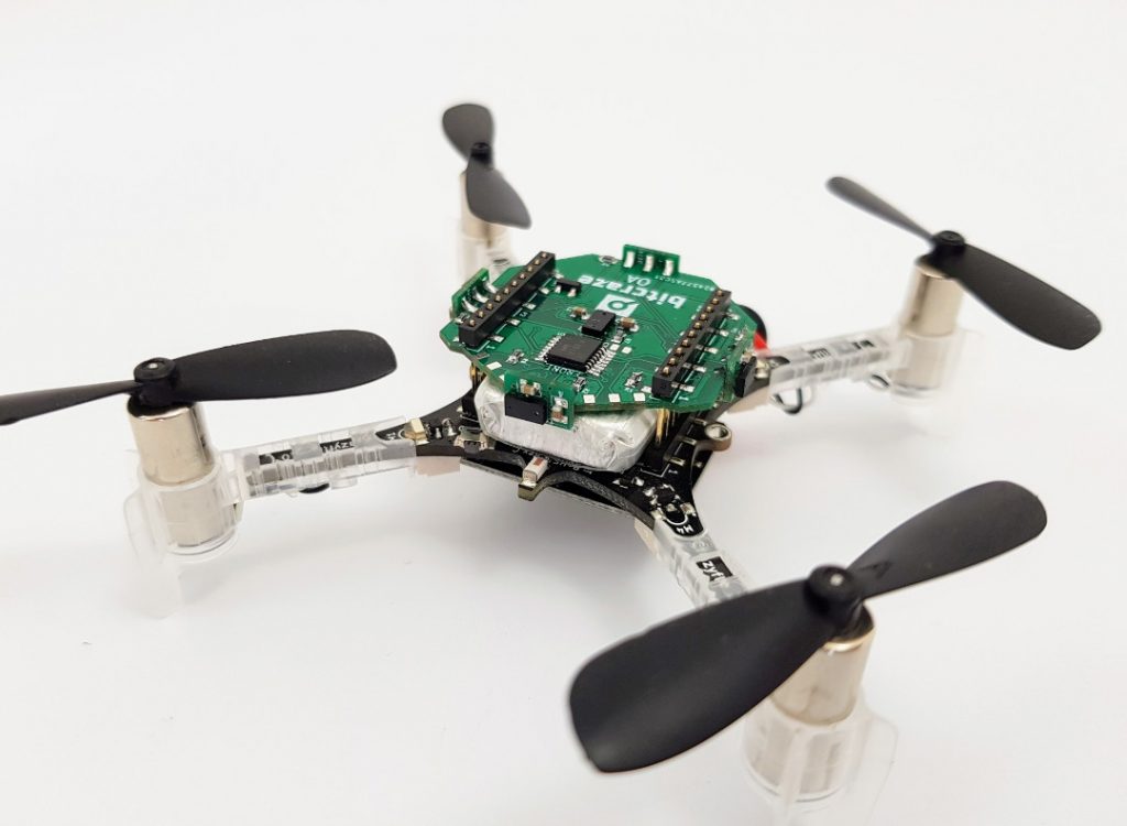
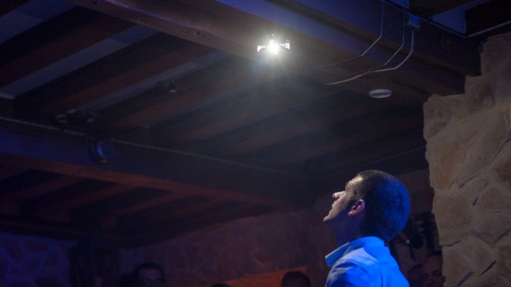
The last couple of weeks has been really busy getting ready for the Maker Faire Berlin. The plan is to show multiple Crazyflies flying autonomously enabled by the Loco positioning system. To spice up the experience of autonomous flight and to inspire the visitors to imagine future applications we have made a small light and sound show where the Crazyflie is dancing to a soundtrack Kristoffer made.

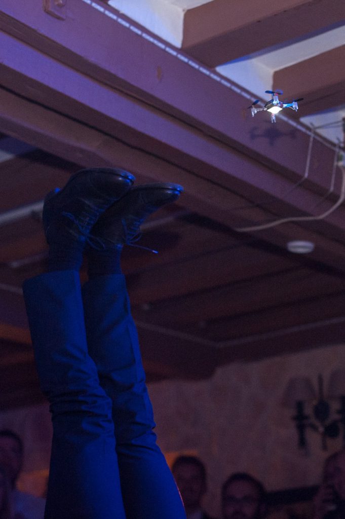
Here is a teaser where we are maybe stretching the limits a bit too far ;-):

Taking the opportunity to exhibit what we do at events like the Maker Faire Berlin is really exciting and we are looking forward to hanging out with cool people and getting feedback about what we do.

So come and visit us at Maker Faire Berlin is Sept 30 to Oct 2 at Station Berlin. You will find us in hall 3, stand 149.

See you there!

Until now, the Loco Positioning System have been limited to flying only one Crazyflie autonomously. In this post we will try to explain the reason of this limitation and what are the way forward.

The loco positioning system is based on Ultra Wide Band (UWB) radios that can very precisely measure the time of departure and arrival of a radio packet. This allows us to do two things:

  1. Use these times directly to calculate the flight time of the radio packet. This is called time of arrival (ToA) measurement, it can be done by simply pinging one anchor. No extra synchronization is required.
  2. Use the difference between the arrival of packets from two different anchors. This is called time difference of arrival (TDoA), it requires the system of anchors to be synchronized together.

The method 1) is simpler to implement since it does not require the anchor system to be synchronized, though it requires bidirectional communication between the tag (eg. Crazyflie) we want to locate and the anchors. It means that if you want to locate more than one tag you have to somehow share the air by not ranging all at the same time. The method 2) requires extra work to synchronize the system of anchor and is theoretically more sensitive to measurement noise. However TDoA measurements have a huge advantage: they can be made to work with unidirectional signal sent from the anchors. This means that the tag only has to listen to the air to receive all information needed to locate itself. This allows to scale the location system to as many tag as we want since adding a tag do not have to share the air, they are not transmitting anything.

So far we have been concentrating on ToA measurement since it could easily be implemented and gives us the best theoretical ranging performance. This allows to develop the algorithms to calculate position estimates and stabilize the autonomous flight. The problem is that, since we are just ranging as fast as possible with all the anchors of the system, one Crazyflie will take all the available air-time and we cannot fly another Crazyflie at the same time. We have just implemented a solution to fly more than one Crazyflie with ToA measurement using time-slots, this is called TDMA for Time Division Multiple Access, and it can be done without anchor code modification. We are working on the Maker Faire demo using this method and it is starting to work quite well:

For TDMA we define frame and time slot. One time slot is a space in time where one tag will be allowed to communicate without risking collision with others. One frame is a group of timeslot. Each Crazyflie is configured to use one time slot in each frame.

TDMA frame structure. Image from the Wikipedia TDMA article.

TDMA frame structure. Image from the Wikipedia TDMA article.

Normally implementing TDMA would require some kind of synchronization to make sure each Crazyflie knows when its time slot starts. With the LPS we are in luck though since transmitting time is part of the way the ranging is working: we do not have to implement new messages or even to modify the anchors to implement TDMA.

We chose the timer in anchor 1 as our master clock for TDMA. When a Crazyflie starts it ranges with anchor 1 which allows to get the current time in anchor 1, then the start of the next frame can be calculated and the Crazyflie can schedule to range in its next time slot. We range with one anchor per time slot and each time we range with anchor 1 we get a chance to re-synchronize.

The TDMA has been pushed to the Crazyflie master branch. It is documented in the commit message so please feel free to test it, report, and pull-request ;-). We have tested running in 2 slots mode with success. Very quickly though, when adding more time slots, the performance deteriorates because the rate of ranging per Crazyflie decreases. Then TDoA will lead to better performance which is the next target, after the Maker Faire Berlin :-).


It’s been over six months since our last Crazyflie 1.0/2.0 firmware release and it was about time to do a new one. We have always had the idea to release often but can’t really say we have succeed. Something we are trying to improve but it has turned out to be really hard. Since it has been quite some time since the last release a lot of things have happens. To summarize the bigger ones:

  • There is now a Kalman filter option to use with the Loco Positioning system and hopefully later with other systems such as GPS and camera based systems (thanks to @mikehamer)
  • Improved altitude hold
  • Rewrites of low level code to improve stability
  • Architecture updated to support on-board position awareness
  • New streamlined I2C driver
  • Driver for Loco Positioning deck
  • CMSIS-DSP added to the firmware project
  • Improved PID tuning for the Crazyflie 2.0 (thanks to @theseankelly)
  • More reliable radio communication link

Please go to this page for instructions about how to upgrade to release 2016.09

CF2 release

ST Microelectronics have become quite known for their complex and somewhat buggy I2C peripheral, especially for their STM32F103 device (see errata). Where for instance the I2C interrupt priority needs to be the highest in the system, otherwise some I2C events might be lost which could cause random behavior. Since we use the STM32F103 for the Crazyflie 1.0 we have been using ST provided drivers as a solution for not having to take care of these cases. On the Crazyflie 2.0 we’re using the STM32F405 which doesn’t have the same I2C implementation and where ST has moved over to using the CPAL library for I2C drivers. This driver has turned out to be “bulky” and cause compatibility problems with our FreeRTOS due to handling of CPAL timeouts. Therefore we recently decided to see if we could write our own driver for the STM32F405 instead. How hard can it be..? Well after two weeks of pulling my hair and swearing it turned out to be a bit harder than we first thought. But now we hopefully have a slick and optimized I2C driver that works great for our purpose. Instead of polling it uses interrupts for I2C writing and DMA for I2C reading to keep MCU intervention low, leaving more processing power to Kalman filters etc :-).

Like I said, there was a few more obstacles along the way than we initially thought. So here are are some pointers I collected on the way:

  • I quickly dropped the interrupt event handling the ST-LIB suggest, I2C_GetLastEvent(…), because during the address event status register 2 (SR2) needs to be cleared (by reading it) after DMA has been setup (as noted in the datasheet when reading the fine print…). The I2C_GetLastEvent reads SR1 and SR2 at once which thus doesn’t work out.
  • This took most time to find, but using my I2C analyser I found that the I2C connection suddenly stopped after a small period of time with a START then STOP event of 3.9us. Doing a lot of trial and error a eventually found that the only way to trigger such a quick start-stop condition was if both the start and stop flag in the control register where set at once. I therefore tried manipulating the CR1 register only with a write operation and not a read-modify-write which solved the problem. This requires that you know what the whole content of the register needs to be when setting it. Luckily such is the case. A very strange behaviour but now it’s working, let’s leve it at that :-)
  • And finally don’t always trust the tools. I found that using my TotalPhase Beagle I2C analyzer I sometimes got corrupt transactions. I tried a lot of things in my I2C driver but I didn’t get why. I posted a topic in the ST forum to get some desperately needed help but then one of my colleges suggested that I should try a different analyser. Well there was no problems with the I2C bus according to that analyser. Turned out that the problem was that I was using the Totalphase Data Center software in a virtual machine. I couldn’t get it to run natively on Ubuntu, which must have been causing slow USB communication or something that the Data Center software doesn’t handle correctly.

    Random corrupt I2C transaction when used in VM

    Random corrupt I2C transaction when used in VM

icon_Berlin_dt-150x150@2x

Maker Faire Berlin 2016 is coming up and we will be there to show of the latest and greatest from our lab. The plan is to show:

  • the Loco Positioning system and autonomous flight
  • a (small) swarm – we hope to get more than one Crazyflie in the air at the same time, even though the space is very limited
  • there are ideas of some sort of synchronized sound- and light show with an autonomous Crazyflie, all controlled from a MIDI sequencer
  • a virtual cage to stop a Crazyflie from escaping when flown manually
  • a preview of the Arduino based controller to fly the Crazyflie
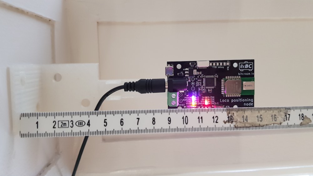
  • a Loco Positioning tag that can be used to track other devices/robots than the Crazyflie
  • ROS integration with the Crazyflie and Loco Positioning system

We’re not sure we will succeed with them all, but let’s hope for the best. Is there anything special you are interested in? Please let us know!

Maker Fair Berlin is Sept 30 to Oct 2 at Station Berlin. You will find us in hall 3, stand 149.

We love your feedback and are looking forward to meeting you all and talk about your projects, what we do and future ideas.

See you in Berlin!


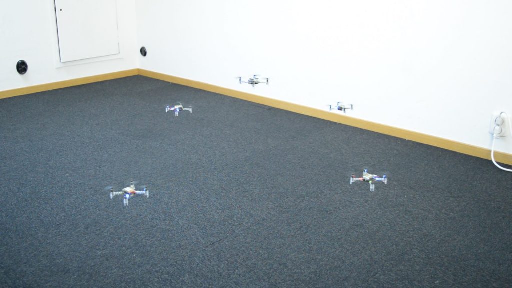
What’s better than a single Crazyflie? A swarm of them! Over a year ago our research group at the University of Southern California posted a blog post with the title “Towards CrazySwarms“, explaining how to fly six Crazyflies at the same time. Since then, we’ve expanded our fleet to 49 Crazyflies. It turns out that flying 49 requires a completely different approach. We will outline the additional challenges, and of course show a fun video!

Why is flying many Crazyflies hard? It comes down to two different categories:

  1. Communication Limitations: The standard Crazyflie software does not support controlling more than one crazyflie per radio. Putting 49 radios on a PC is possible, but would cause very high latencies because the Universal Serial Bus (USB) operates, as the name suggests, serially in 1 ms intervals. Earlier, we showed that we can share a radio for two Crazyflies by using different addresses, but 25 radios are still too much to be handled on one PC reasonably. We can overcome this issue by reducing the amount of data to be transferred. However, this forces us to increase the autonomy of the Crazyflie. Instead of sending attitude control input for each Crazyflie at a high rate, we move the controller on-board and send high-level trajectory descriptions and external position information at a low-rate. In particular, we need to:
    1. Move the position controller on-board, and
    2. Be able to handle packet losses more gracefully.

    i) is relatively easy, apart from the testing and tuning. For ii) we use an Extended Kalman Filter to estimate the state on-board. This state, consisting of the position, angle, and the translational velocities, is estimated by combining the on-board sensors (gyroscope, accelerometer) with external position information. Even if we are not able to send the external position for a while due to packet drops, the on-board sensors will keep the estimated state correct for a while.
    Finally, we implemented broadcasts (rather than 1-to-1 communication between PC and each Crazyflie) and used a number of compression tricks in order to limit the required bandwidth further. We are able to broadcast the pose (position and rotation) for all 49 Crazyflies using just three Crazyradios 100 times per second. Each Crazyflie can handle several packet drops in a row before the state estimate becomes too unreliable to fly.

  2. External Position Feedback: The on-board sensors of the Crazyflie are not sufficient to determine its position, so we need some external position feedback. In academia, optical motion capture systems are frequently used. They consist of a number of specialized, synchronized, high-speed infrared cameras. Each object to track is equipped with at least three retroreflective spheres (so-called markers), which reflect infrared light sent out by the IR light sources next to the cameras. If we know the pose of all cameras, we can use triangulation to determine the 3D positions of all retroreflective markers.Traditionally, motion capture systems require that each object has a unique arrangement of markers; this allows to determine each object’s position from a single frame of marker data by searching for its unique pattern. Unfortunately,  the Crazyflie is too small to have 49 unique marker arrangements that can be reliably distinguished. To solve that issue, we put the Crazyflies at known positions initially and use their marker arrangement to track their position and pose over time, at 100 Hz. This allows us to use the same marker arrangement for each Crazyflie.


Putting that together (combined with an improved controller), allows us to create nice formations:

So what is next? Eventually, we will integrate our changes into the various projects (including the firmwares and the ROS driver), allowing everyone to work on and with CrazySwarms.

Have fun flieing!

Wolfgang Hönig
PhD Student
Automatic Coordination of Teams Laboratory
University of Southern California
James Preiss
PhD Student
Robotics Embedded Systems Laboratory
University of Southern California

Summertime is a good time to get outside and play :-). For a long time we have been having an assembled Turnigy tylon frame here at the office just lying around and it was time to put a camera on it and test its wings. It is not really a frame built to host a camera, and the least to put a gimbal on it but the size supports it so why not. So that is what I did, which included plenty of tape, zip-ties, drilling etc. Wouldn’t really recommend this frame and maybe that is why they quickly made a new version. I had a really hard time fitting the motors to the mounts which required getting some motor mount adapters and drilling into the aluminium mount to make them fit. To make the gimbal fit I made some wood extensions of the legs, as that was what I could find lying around. Anyway the result wasn’t that bad so I decided to give it a go. The first flight is always a bit nervous and especially with bigger quads so I took a lot of precautions and triple checked important things. The flight went well without any crash and I just used the stock PID settings when building the firmware. I flew it with the python client and a PS3 gamepad as I normally fly the CF2 and a was watching the signal strength carefully when getting far away. It will not survive a drop from 50m as the CF2 might. The basic functionality of the BiqQuad deck works well but I must admit that there are plenty more to implement before it has a rich feature set.

Unfortunately I’m not allowed to publish the onboard GoPro video I took as it captured some public areas (if I interpret the Swedish law correctly).

It is summer time and the tempo in the office is a somewhat slow as most of the Bitcrazers are on vacation recharging their batteries for future awesomeness. This weeks blog post will not contain any cool tech stuff but instead I will tell you a bit about how we work. This is a moving target as we are continuously changing and improving, but I can share a snapshot of how it works right now.

Basics

We have two basic principles that all our work is based on: self organization and continuous improvement.

Our take on self organization can be boiled down to the simple idea that no one in the company can decide what someone else must do. That is right, no one (or every one) is a boss! The result is that we have to find solutions that everyone can accept, this in turn requires complete trust and respect within the company.

Continuous improvement means that we try to become better at what we do. If we fail we try to understand why and find a better way next time. If we succeed we enjoy the success and then we try to understand why we were successful and find an even better way. The key ingredient is feedback, based on (again) respect and trust.

How we do it

Planning can be a useful tool but it can also be expensive when overused. Plans give a shared direction but the cost is that they take time to maintain, they tend to reduce agility and most likely they will be more or less wrong. We try to balance this by planning as little as possible and making long term plans less detailed. We consider planing to be a an opportunity for discussions and the actual plan as a documentation of the discussion. The discussion is more important than the plan it self.

Our long term direction is set by our purpose – the reason we go to work and invest all these hours into this project. We have tried to form one single sentence that captures this and the latest version is “Together we innovate and explore robotics”. The sentence it self is not that important but the discussions leading up to the sentence is what matters.

From the purpose we have tried to create a one year plan and a three year plan based on what we all would like to achieve in the coming years. This is very much a wish list, pretty vague. Every quarter we create a quarterly plan based on the one year plan. This is a list of areas we think are important to work with in the coming tree months, it usually does not contain very specific goals but gives us a good idea of what to do.

board

Björn at the whiteboard writing fake sticky note and looking busy

We kick off every week with a feedback and planing meeting. We look back at the previous week and investigate what we did, why we did it, the outcome and what we felt. When we have agreed on the past we turn to the future and decide what we think are the most important things to work on in the coming week. We also decide on a few experiments that we want to try out that we think will improve the way we work and increase our happiness.

We start every day with a short standup meeting to synchronise the team, understand how we can help each other and make sure we are doing the right thing.

The rest is just hard work :-)

Some inspiration

More about self organization. and what is motivating us?


aman_sharma

Going out of the norm for this week, this blog post is about my experience as an intern at Bitcraze. My name is Aman and I joined Bitcraze 8 weeks ago hoping to gain more experience and knowledge in quadcopter robotics while building some new connections.

Working at Bitcraze has been a breath of fresh air compared to all my previous internship experiences. From the work environment to the five brilliant guys that run this company, I believe everything was setup for me to have one of the best internship experiences. Someone was always available to help me with any concept I did not understand and even though I was just an intern, each of the guys made sure to include me in every part of the planning process. This type of inclusion, I believe, allowed me to see my role in the company and how I contributed to the overall goals.

While here, I mainly focused my work on the flight control software behind the Crazyflie. This included learning and understanding the framework behind the crazyflie, tweaking the existing firmware code to get location data, converting MATLAB code to Python that would provide location of all the anchors in a Loco Positioning setup by simply moving the crazyflie around, designing a filter that would provide more stability during flight operations during ‘Fun Fridays’ (definitely a great idea), etc. Also, with Arnaud’s help, I was able to learn how to juggle while I taught him how good peanut butter goes with bananas.

In my opinion, the reason for Bitcraze’s success and the reason it is such an amazing place to work is because of the way the company is setup. They follow a company structure called ‘self organizing’. Having never heard of it before or experienced it before, I was a bit thrown off when I first started working in this environment. Here at Bitcraze, there is no heirarchy, but, instead everyone is a leader of their own individual roles, a concept I believe allows them to solve even the most difficult of problems with ease. Once I acclimated to this, working for Bitcraze tenfolded in awesomeness. The only downside, though, you will never want to work anywhere else again.

During my experience here, I have gained a plethora of skills and have had many great experiences. Most importantly, however, I have built great relationships and learned that where you work and who you work with is just if not more important than what you work on.

PS: They love visitors here, so feel free to come and hangout with the guys!

–  Aman

Thanks!

We have enjoyed your internship a lot! You quickly adapted to our crazy way of working and became a natural member of the team, adding not only your technical skills but also your personality and new angles on what we do.

We hope we will see more of you in the future!

–  The rest of the Bitcraze team

As noted in a previous post, Mike Hamer from ETH Zurich has been implementing an Extended Kalman Filter (EKF) for the Crazyflie. The beginning of this week I am visiting Michael at ETH and we have now pushed the EKF to the Crazyflie master branch!

Visiting ETH is really nice, and it is very impressive to see the Flying Machine Arena in real life. Though, owing to the Crazyflie’s size, we do not need such a big space and can work in a more regular-sized room.

The EKF has now been added to the master branch but is not enabled by default. It is currently intended to be used with the Loco positioning system (although it should be easy enough to integrate with onboard GPS, or potentially offboard motion capture measurements). While it does fly better than the currently used, offboard particle filter for autonomous flight, it requires some care to work properly. I am going to update the wiki description for the loco positioning to document how to get started with the EKF during the week. Our hope is that through community engagement and feedback, we can continue to improve and tune the filter, now that Mike has put the basic functionality in place.

The greatest enhancement is that the Crazyflie is now able to estimate its own position, without the help of an external computer. Coupled with the onboard controller, the Crazyflie can now fly fully autonomously. I have also pushed a new example in the Crazyflie python lib that shows how to send an X/Y/Z set-point to fly the Crazyflie, allowing it to fly through waypoints.

In the near future we (Bitcraze, and hopefully, the community!) need to work on a couple of more things to make it fly even better

  • Revamp of the controller: the current controller is a position controller, splitting it in two controllers, one for position and one for velocity, would allow for a more stable flight and to finally use TheSeanKelly new PID settings!
  • Implementing TDOA positioning on the LPS would allow more than one Crazyflie to fly at the same time
  • Implementing the new commander packet in the Crazyflie, python lib and ROS driver. This will allow us to stop hacking the current commander each time we need a new functionality (such as onboard position control) — and since I have push rights, only my hacks get pushed, which is unfair ;-).

Mike will describe the Kalman filter in greater details in a future post. In the mean time we will update on the progress in the Loco Positioning mailing list.