Category: Guest-blogger

This week we have a guest blog post from Javier Burgués. Enjoy!

I would like to introduce you a rather unknown application of the CrazyFlie 2.0 (CF2): chemical sensing. Due to its small form-factor, the CF2 is an ideal platform for carrying out gas sensing missions in hazardous environments inaccessible to terrestrial robots and bigger drones. For example, searching for victims and hazardous gas leaks inside pockets that form within the wreckage of collapsed buildings in the aftermath of an earthquake or explosion.

To evaluate the suitability of the CF2 for these tasks, I developed a custom deck, named the MOX deck, to interface two metal oxide semiconductor (MOX) gas sensors to the CF2. Then, I performed experiments in a large indoor environment (160 m2) with a gas source placed in challenging positions for the drone, for example hidden in the ceiling of the room or inside a power outlet box. From the measurements collected in motion (i.e. without stopping) along a predefined 3D sweeping path that takes around 3 minutes, the CF2 builds a map of the gas distribution and identifies the most likely source location with high accuracy.

1. MOX deck

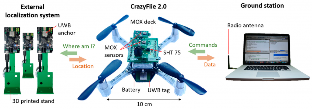
The MOX deck (Fig. 1a) contains two sockets for 4-pin Taguchi-type (TGS) gas sensors, a temperature/humidity sensor (SHT25, Sensirion AG), a dual-channel digital potentiometer (AD5242BRUZ1M, Analog Devices, and two MOSFET p-type transistors (NX2301P, NEXPERIA). I used TGS 8100 sensors (Figaro Engineering) due to its compatibility with 3.0 V logic, power consumption of only 15 mW (the lowest in the market as of June 2016) and miniaturized form factor (MEMS). Since the sensor heater uses 1.8V, two transistors (one per sensor) reduce the applied power by means of pulse width modulation (PWM). The MOX read-out circuit (Fig. 1b) is a voltage divider connected to the μC’s analog-to-digital converter (ADC). The voltage divider is powered at 3.0 V and the load resistor (RL) can be set dynamically by the potentiometer (from 60 Ω to 1 MΩ in steps of 3.9 kΩ). Dynamic configuration of the load resistor is important in MOX gas sensors due to the large dynamic range of the sensor resistance (several orders of magnitude) when exposed to different gas concentrations. The sensors were calibrated (by exposing them to several known concentrations) to convert the raw output into parts-per-million (ppm) concentration units.

The initialization task of the deck driver configures the PWM, initializes the SHT25 sensor, sets the wiper position of both channels of the potentiometer and adds the MOX readout registers to the list of variables that are continuously logged and transmitted to the base station. The main task of the deck driver reads the MOX sensor output voltage and the temperature/humidity values from the SHT25 and sends them to the ground station at 10 Hz.

2. Experimental Arena, External Localization System and Gas Source

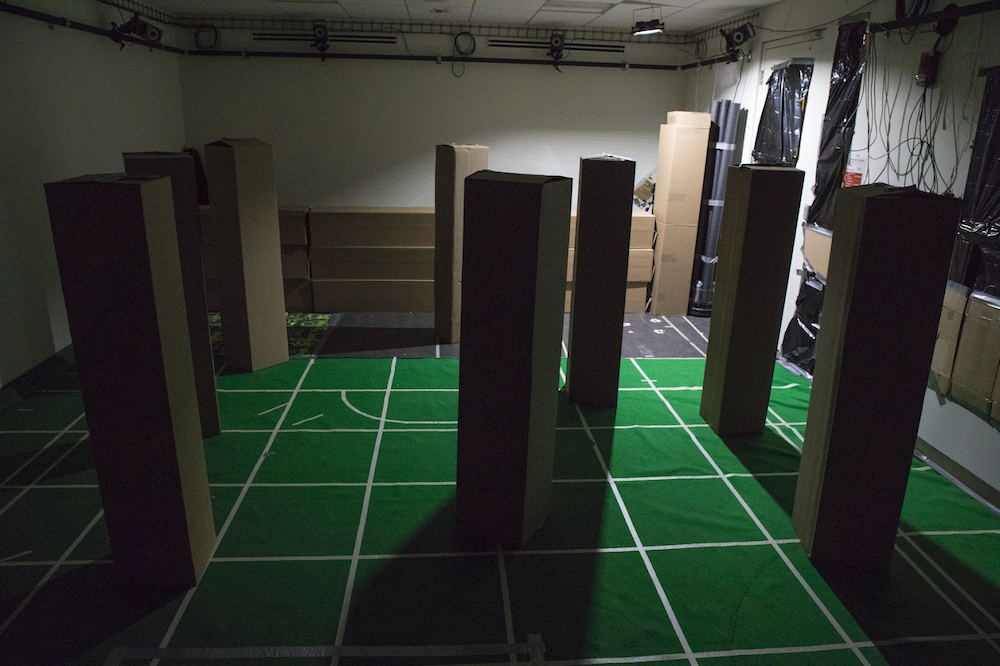
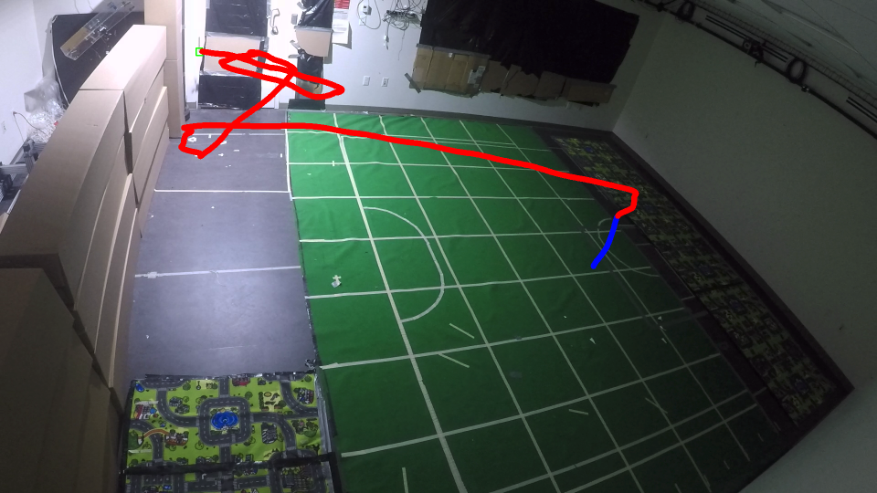
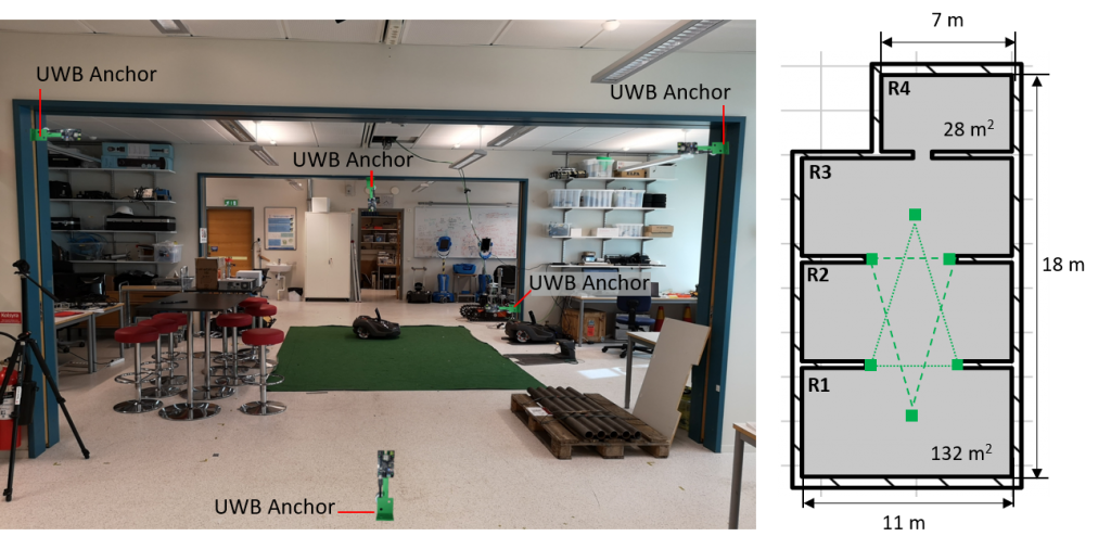
Experiments were performed in a large robotics laboratory (160 m2 × 2.7 m height) at Örebro University (Sweden). The laboratory is divided into three connected areas (R1–R3) of 132 m2 and a contiguous room (R4) of 28 m2 (Fig. 2). To obtain the 3D position of the drone, I used the Loco positioning system (LPS) from Bitcraze, based on ultra-wide band (UWB) radio transmitters. Six LPS anchors were positioned in known locations of the experimental arena and one LPS tag was fixed to the drone. The six LPS anchors were placed in the central area of the laboratory, shaped in two inverted triangles (below and above the flight area).

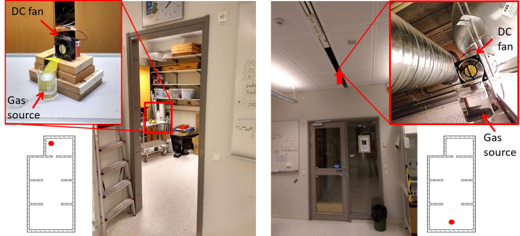
A gas leak was emulated by placing a small beaker filled with 200 mL of ethanol 96% in different locations of the arena (Fig. 4). Ethanol was used because it is non-toxic and easily detectable by MOX sensors. Two experiments were carried out to check the viability of the proposed system for gas source localization and mapping in complex environments. In the first experiment, the gas source was placed on top of a table (height = 1 m) in the small room (R4). In the second experiment, the source was placed inside the suspended ceiling (height = 2.7 m) near the entrance to the lab (R1). Since the piping system of the lab runs through the suspended ceiling, the gas source could represent a leak in one of the pipes. A 12 V DC fan (Model: AD0612HB-A70GL, ADDA Corp., Taiwan) was placed behind the beaker to facilitate dispersion of the chemicals in the environment, creating a plume. The experiments started five minutes after setting up the source and turning on the DC fan.

3. Navigation strategy

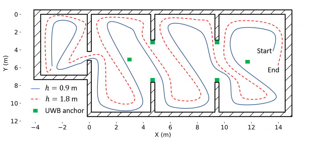
The drone was sent to fly along a predefined sweeping path consisting of two 2D rectangular sweepings at different heights (0.9 m and 1.8 m), collecting measurements in motion (Fig. 5). These two heights divide the vertical space of the lab in three parts of equal size. Flying first at a lower altitude minimizes the impact of the propellers’ downwash in the gas distribution. For safety reasons, the trajectory was designed to ensure enough clearance around obstacles and walls, and people working inside the laboratory were told to remain in their seats during the experiments. The ground station communicates the flight path to the drone as a sequence of (x,y,z) waypoints, with a target flight speed of 1.0 m/s. The CF2 reports the measured concentration and its location to the ground station every 100 ms.

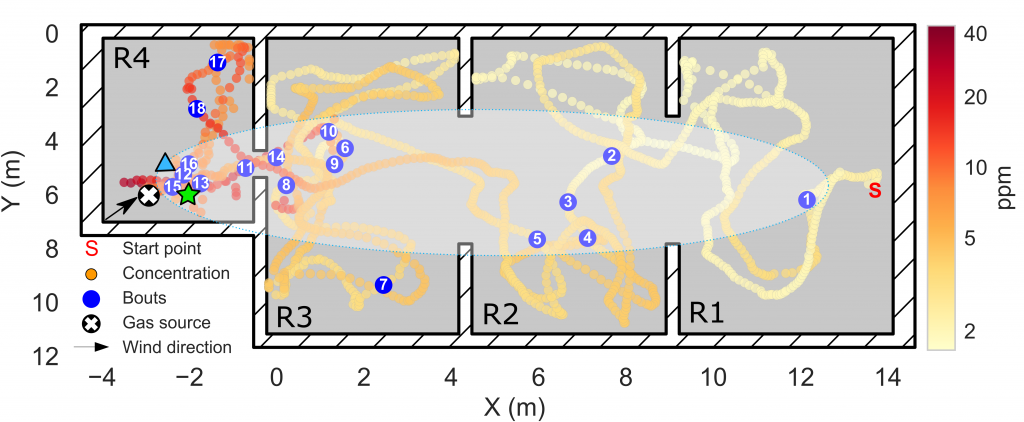
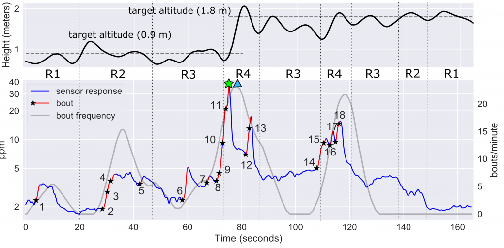
At the end of the exploration, the ground station uses all the received information to compute a 3D map of the instantaneous concentration and the ’bouts’. A ’bout’ is declared when the derivative of the sensor response exceeds a certain threshold. Bouts are produced by contact with individual gas patches and some authors use them instead of the instantaneous response (which is more affected by the slow response time of chemical sensors). For gas source localization, we compare two approaches: using the cell with maximum value in the concentration map or using the cell with maximum bout frequency. The bout frequency (bouts/min) is computed as the bout count in a 5 second sliding window multiplied by 12 (to convert it to bouts/min).

4. Results

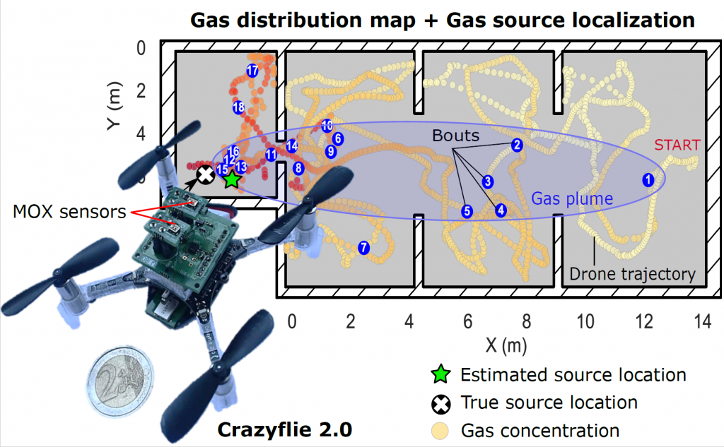
In the first experiment, the drone took off near the entrance of the lab (R1), 17 meters downwind of a gas source located in the other end of the laboratory (R4). From the gas distribution map (Fig. 6a) it is evident that the gas source must be in R4, because the maximum concentration (35 ppm) was found there while concentrations below 5 ppm were measured in the rest of the lab. The gas plume can be outlined from the location of odor hits. The highest odor hit density (25 hits/min) was found also in R4. The cells corresponding to the maximum concentration (green start) and maximum odor hit frequency (blue triangle) were found at 0.94 and 1.16 m of the true source location, respectively.

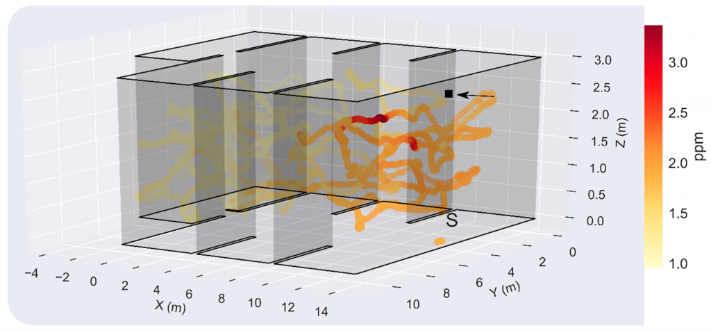
In the second experiment, the gas source was located just above the starting point of the exploration, hidden in the suspended ceiling (Fig. 7). The resulting maximum concentration in the test room was measured when the drone flew at h=1.8 m, highlighting the importance of sampling in 3D for localization and mapping of elevated gas sources. However, since the source is presumably not directly exposed to the environment, concentrations below 3 ppm were found in most locations of the room, which complicates the gas source localization task. The concentration and odor hit maps suggest that the gas source is located in the division between R1 and R2, which represents a localization error of 4.0 and 3.31 m, respectively.

5. Conclusions

These results suggest that the CF2 can be used for gas source localization and mapping in large indoor environments. In contrast to previous works in which long measurement times were taken at predefined or adaptively chosen sampling locations, a rough approximation of such maps can be obtained in very short time with concentration measurements acquired in motion. The obtained gas distribution maps seem coherent with respect to the true source location and wind direction, and not only enable the detection of the source with relatively small localization errors but also provide a rich visual interpretation of the gas distribution.

If you are interested in more details about this work, take a look at the journal paper or drop me an email at <jburgues8 at gmail dot com> or leave a comment on the blog!

This week we have a guest blog post from Percy Jaiswal about quad rotor dynamics. Enjoy!

  1. Components
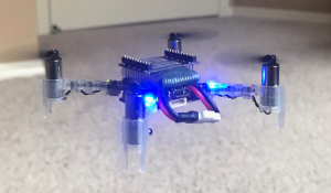
    Although most of us are aware how a quadcopter / drone looks, a generic picture (It’s of a drone called Crazyflie from Bitcraze) of drone is shown above. It consists of 4 motors, control circuitry in middle and Propellers mounted on its rotors. For reasons described in below section, 2 of the rotors rotate in clockwise (CW) direction and remaining 2 in counterclockwise (CCW). CW and CCW motors are placed next to each other to negate Moment (described in next section) generated by them. Propellers come in different configurations like CW or CCW rotating, Pusher or Tractor, with different radius, pitch etcetera.
  2. Force and Moments

    Each rotating propeller produces two kind of forces. When a rotor rotates, it’s propeller produces upward thrust given by F=K_f * ω² (shown by forces F1, F2, F3 and F4 in Figure 2) where ω (omega) is rotation rate of rotor measured in radian / second. Constant K_f depends upon many factors like torque proportionality constant, back-EMF, Density of surrounding air, area swept by propeller etc. The values for K_f​ and K_m (mentioned below)​ are generally found empirically. We mount the motor and propeller on a load cell and measure the force and moment for different motor speeds. Refer “System Identification of the Crazyflie 2.0 Nano Quadrocopter” by Julian Forster for details regarding measurement of K_f and K_m.
    Total upward thrust generated by all 4 propellers is given by summing all individual thrusts generated, for i= 1 to 4 its given by
    F_i = K_f * ω²
    Apart from upward force, a rotating propeller also generates an opposing rotating spin called Torque or Moment (shown by Moments M1, M2, M3 and M4 in Figure 2). For e.g. a rotor spinning in CW direction will produce a torque which causes the body of drone to spin in CCW direction.  A demonstration of this effect can be seen here. This rotating torque is given by M=K_* ​ω²
    Moment generated by a motor is in opposite direction to its spinning, hence CW and CCW spinning motors generate opposite moments. And this is the reason why we have CW and CCW rotating motors so that in steady hover state, moments from 2 CW and 2 CCW rotating rotors negate each other out and drone doesn’t keeping spinning about its body axis (also called yaw).
    Moments / Torques M1, M2, M3 and M4 are moments generated by individual motors. The overall Moment generated around drone’s z axis (Z_b in Figure 2) is given by summation of all 4 moments. Remember that CW and CCW moments will have opposite signs.
    moment_z = M1 + M2 + M3 + M4, again CW and CCW moments will have opposite signs and hence in ideal condition (or whenever we don’t want any Yaw (rotation around z axis) movement) moment_z will be close to 0.
    Contrary to moment_z, overall moment / torque generated around x and y axis’s calculations are little different. Looking at Figure 2, we can see that motor 1 and 3 lie on x axis of drone. So they won’t contribute to any moment / torque around x axis. However we can see that difference in forces generated by motor 2 and 4 will cause drone’s body to tilt around it’s x axis and this is what constitutes overall moment / torque around x axis, which is given by
    moment _x = (F2 — F4) * L, where L is the distance from the axis of rotation of the rotors to the center of the quadrotor. By same logic,
    moment _y = (F3 — F1) * L.
    Summing it up, moment around all 3 axis can be denoted by below vector
    moment = [moment_x, moment_y, moment_z]^T (^T for Transpose)

  3. Orientation and position

    A drone has positional as well as orientational attributes, meaning to say it can be any position (x, y, z coordinates) and can be making certain angles (theta (θ), phi (φ) and psi (ψ)) with respect to world / Inertial frame. Above figure shows theta (θ), phi (φ) and psi (ψ) more clearly.
  4. Moving in z and x & y direction

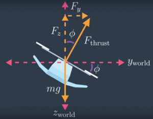
    Whenever a drone is stationary, it’s in alignment with World frame, meaning to say its Z axis is in same direction as World’s gravitational field. During such a case, if a drone wants to move upwards, it just needs to set proper propeller rotating speed and it can start moving in z direction according to equation total generated force — gravity. However, if it wants to move in x or y direction it first needs to orient itself (making required theta or phi angle). When that happens, total thrust generated by four propellers (F_thrust) has a component in z direction and in x/y direction as shown in above 2D figure. For above shown example, using basic trigonometry, we can find z and y directional force by following equation, where phi is angle made Drone’s body z axis with world Frame.
    F_y ​= F_thrust * ​sinϕ
    F_z ​= F_thrust * ​cosϕ
  5. World and Body frame

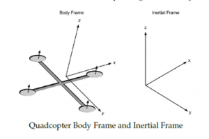
    To measure above stated theta, phi and psi angles, usually drone’s onboard IMU sensor is used. This sensor measures how fast drone’s body is rotating around its body frame and provides that angular velocity as its output. When processing this IMU outputs, we need to be careful and understand that angular velocities sent by it are not with respect to World frame, but are with respect to its Body Frame. Above diagram shown both this frames for reference.
  6. Rotation Matrix

    To convert coordinates from Body Frame to World Frame and vice versa, we use a 3×3 matrix called Rotation Matrix. That is, if V is a vector in the world coordinates and V’ is the same vector expressed in the body-fixed coordinates, then the following relations hold:
    V’ = R * V and
    V = R^T * V’ where R is Rotation Matrix and R^T is its transpose.
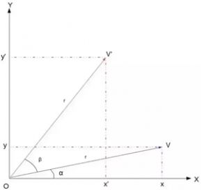
    To understand this relation completely, let’s begin by understanding rotation in 2D. Let the vector V be rotated by an angle β to get the new vector V′. Let r=|V|. Then, we have the below relations:
    vx = r*cosα and vy = r*sinα
    v’x = r*cos(α+β) and v’y = r*sin(α+β). Expanding this, we get
    v’x = r * (cosα * cosβ — sinα * sinβ) and v’y = r * (sinα * cosβ + cosα * sinβ)
    v’x = vx * cosβ — vy * sinβ and v’y = vy * cosβ + vx * sinβ
    This is exactly what we want because the desired point V’ is described in terms of the original point V and the actual angle β. For conclusion we can write this in matrix notation as

    Going from 2D to 3D is relatively simple in Rotation Matrix’s case. In fact, the 2D matrix we just now derived can actual be thought of as an 3D rotation matrix for rotation around z axis. Hence, for a rotation around z-axis the Rotation Matrix would be

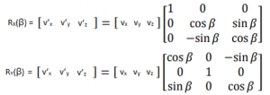
    0, 0, 1 in values in last row and column indicate that z coordinates for rotated point (v’z) is same as original point’s z coordinate (vz). We will call this Z axis Rotation Matrix as Rz(β). Extrapolating same logic to rotations around x and y axis, we can get values for RX(β) and RY(β) as

    And final value for 3D motion Rotation Matrix will just be cross multiplication of above three Rotation Matrices.
    R = Rz(ψ) x Ry(θ) x Rx(φ), where psi (ψ), phi (φ,) and theta (θ) are rotation around z, y, and x axis respectively.

  7. State Vector and its Derivative
    As our drone has 6 degrees of freedom, we usually track it by monitoring this six parameters along with their derivatives (how they are changing with time) to get an accurate estimate of drone’s position and velocity of movement. We do this by maintaining what is often called a state vector X = [x, y, z, φ, θ, ψ, x_dot, y_dot, z_dot, p, q, r] and its derivative X_dot= [x_dot, y_dot, z_dot, θ_dot, φ_dot, ψ_dot, x_doubledot, y_doubledot, z_doubledot, p_dot, q_dot, r_dot] where x, y and z are position of drone in World frame, x_dot, y _dot, and z_dot are positional / linear velocities in World Frame. φ, θ, ψ represent drone attitude / orientation in World frame whereas φ_dot, θ_dot, ψ_dot represents rate of change of this (Euler) angles. p, q, r are angular velocities in body frame whereas p_dot, q_dot and r_dot are its derivate (derivative = rate of change) aka angular acceleration in body frame. x_doubledot, y_doubledot, z_doubledot represents linear accelerations in World Frame.
  8. Linear Acceleration
    As briefed before, whenever propellers are moving, drone will start moving (accelerating) in x, y and z direction depending upon total thrust generated by it’s 4 propellers (represented by Ftotal in below equation) and drone’s orientation (represented by Rotation Matrix R). We know force = mass * acceleration. Ignoring Rotation Matrix R, if we just consider acceleration in z direction, it would be given by
    Z_force = (mass * gravitational force) — (mass * Z_acceleration)
    mass * Z_acceleration = mass * gravitational force — Z_force
    And therefore Z_acceleration = gravitational force — Z_force / mass
    Extrapolating it to x and y direction and including Rotation Matrix (for reasons described in section 4 and 6), equation describing linear acceleration for a drone is given by below equation, where m is mass of drone and g is for gravitational force. Negative sign in F indicates that we are considering gravitational force to be in positive z direction.
  9. Angular acceleration
    Along with linear motion, owing to rotating propellers and its orientation, drone will also have some rotational motion. . While it is convenient to have the linear equations of motion in the inertial / world frame, the rotational equations of motion are useful to us in the body frame, so that we can express rotations about the center of the quadcopter instead of about our inertial center. As mentioned in section 4, we will use drone’s IMU to get its angular accelerations. Let’s consider output from IMU be p, q and r, representing rotational velocities around drone’s x, y and z body axis.
    We derive the rotational equations of motion from Euler’s equations for rigid body dynamics. Expressed in vector form, Euler’s equations are written as

    where ω = [p, q, r]^T is the angular velocity vector, I is the inertia matrix, and moment is a vector of external moment / torques developed in section 2. . Please don’t get confused with usage of ω (as angular velocity) in this section with it’s usage as propeller’s rotation rate. We will stick to usage of ω as rotation rate post this section. We can rewrite above equation as

    Replacing ω with [p, q, r]^T, expanding moment vector and reshuffling above equation we get angular accelerations in body frame as

  10. Rate of change of the Euler angles
    Although drone’s orientation is originally observed in Body frame, we need to convert them to World Frame. Again, we use rotation matrix as per below formula for this purpose. The derivation of this formula is little elongated and is provided in the Reference [6]
  11. Recap
    So to recap what we have learnt so far
    1. A quadcopter has 4 (2 CW and 2 CCW) rotating propellers
    2. Each Propeller creates F =K_f * ω² force in direction perpendicular to its plane and Moment M = K_m * ω² around it’s perpendicular axis.
    3. A drone can be in any x, y, z position and theta (θ), phi (φ) and psi (Ψ) orientation.
    4. When a drone wants to move in z direction (in World Frame) it needs to generate appropriate force (total thrust divided by 4) on each propeller. When it wants to move in either x or y direction (again World Frame), it makes respecting theta / phi angle along with generating required force
    5. When tracking drone’s motion, we need to handle data in World and Body Frames
    6. To convert angular data from Body Frame to World Frame, a Rotational Matrix is used
    7. To track drone’s movements, we keep track of its state vector X and its derivative X_dot
    8. Rotating propellers generate linear accelerations in x, y and z direction as per equation shown in section 8
    9. Rotating propellers generate angular accelerations around z, y and z axis in Body frame as per equation shown in section 9
    10. We convert angular velocities in Body Frame to World Frame Euler angle velocities as per equation shown in section 10.
  12. References
    I don’t want to just list down references, but instead would like to sincerely thank individual authors for their work, without which this article and the understanding which I have gained for drone dynamics would have been almost impossible.
    1. System Identification of the Crazyflie 2.0 Nano Quadrocopter by Julian Forster — http://mikehamer.info/assets/papers/Crazyflie%20Modelling.pdf
    2. Trajectory Generation and Control for Quadrotors by Daniel Warren Mellinger — https://repository.upenn.edu/cgi/viewcontent.cgi?article=1705&context=edissertations
    3. Quadcopter Dynamics, Simulation, and Control by Andrew Gibiansky — http://andrew.gibiansky.com/downloads/pdf/Quadcopter%20Dynamics,%20Simulation,%20and%20Control.pdf
    4. A short derivation to basic rotation around the x-, y- or z-axis — http://www.sunshine2k.de/articles/RotationDerivation.pdf
    5. How do you derive the rotation matrices? — Quora — https://www.quora.com/How-do-you-derive-the-rotation-matrices
    6. Representing Attitude: Euler Angles, Unit Quaternions, and Rotation Vectors by James Diebel — https://www.astro.rug.nl/software/kapteyn/_downloads/attitude.pdf

I would like to sincerely thanks Bitcraze team for allowing me to express myself on their platform. If you liked this post, Follow, Like, Retweet it on Twitter, it will act as encouragement for writing new posts as I continue my journey in becoming a complete Drone engineer.

Till next time….cheers!!


Malmö is known to be very beautiful in June. At least that’s what i’ve heard from the Bitcraze team when we talked about having a meet-n-geek in their offices in Sweden.

I’ve been working on the crazyflies and developing artist friendly interface to control them for a year now, and I always was impressed with their philosophy of work and communication. Over the past year, they’ve helped me and my companies a lot to be able to create the shows we want, with our specific needs and constraints, that researchers don’t have, like fast installation time, or confidence in drone take off (you want to make sure that a drone won’t hit the theater’s director’s head at the very beginning of the show !).


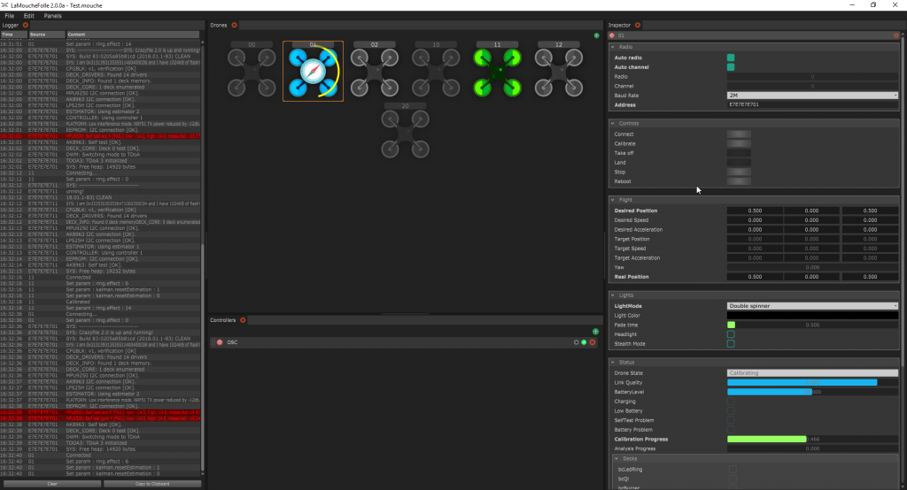
For that I created LaMoucheFolle, which is an open-source software with a nice UI to be able to connect, monitor and control multiple drones. LaMoucheFolle is not made to be a flight controller, but acts more as a server that any software will be able to use, like Unity or Chataigne. That way, people and users don’t need to handle all the connection, feedback, warning, calibration process and can concentrate essentially on the flight and interaction.
While the fist version of LaMoucheFolle got me through most of the demos and workshops, I knew that it could be vastly improved if I understood better the drones, so I decided to ask the creators to meet them, and here I am !

As I hoped, being physically there allowed me to understand better what are their practices, and allowed them to better understand mine, so we could find a way to improve both their Crazyflie ecosystem and my contribution to it.

So I refactored, redesigned and improved LaMoucheFolle to a (soon to be released) V2, featuring :
– New drone manager interface  with a more intuitive feedback of the drones
– New multi-threaded drone communication mechanism
– New state-safe sequenced initialization and flight control of the drone, with a progressive take-off vastly increasing its stability
– Unity demo app and Chataigne demo session to show how to control from other softwares via OSC


While developping the new version and talking to the team, some key features and improvements for the use Crazyflies in shows were discussed and some of them are now in research/development :
– Health analysis : using the accelerometer’s data and Tobias’ magic brain, it allows to test the motors while the drone is on ground and find out if one or more are problematic (too much or not enough vibration, meaning either the propeller or the motor needs to be repaired/replaced)
– Battery analysis : when the battery is fully charged, this allows to have an automated motor sequence which will find out if the battery has an abnormal discharge behavior
– Steath mode : Shut down all the system leds (the 4 builtin leds on the drone) so it can be invisible, ninja-style
– Normalized battery level and low battery log values : it allows for safe and consistent feedback of the battery level in percent, and an indicator if the drone should land soon. It will also possible to use this value to monitor the charging progression of a drone.
– LedRing fade pattern : This mode allows for easy fading between solid colors on the led ring, so it’s not necessary to stream all the colors from one color to another, but instead having a very beautiful smooth interpolation, using only 2 parameters : the target color and the fade time.

I hope you are as excited as I am about those new features, and if you’re not, please tell us what would make you “vibrate” !

I’ve been spending the last week at their office, and it was a great week : I initially came to improve my software, and discuss about future development of the Crazyflies [which was great], but what i’ll remember the most from this trip is by far the human aspect of the Bitcraze team.
Marcus, Kristoffer, Tobias, Björn and Arnaud are amazing and i’m really happy to have had the chance to see them working, and collaborate with them. I admire their choices of being fully transparent on their work and amongst themselves, and there is a natural kindness mixed to the passion for their project that makes working there feel like everyday’s special. Also, Malmö is very beautiful indeed :)

Thank you very much and I hope to reiterate the experience soon,

Skål


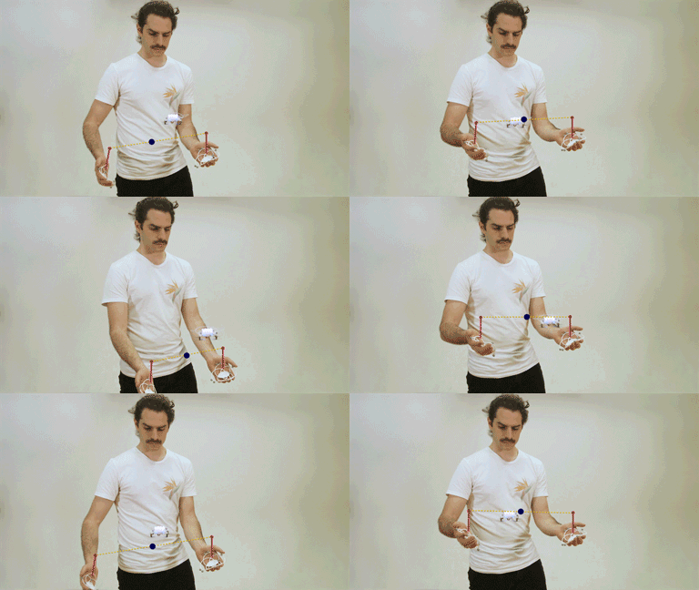
I’ve spent the last 5 years of my career at Microsoft on the team responsible for HoloLens and Windows Mixed Reality VR headsets. Typically, augmented reality applications deal with creating and manipulating digital content in the context of real-world surroundings. I thought it’d be interesting to explore some applications of using an augmented reality device to manipulate and control physical objects and have them interact with the real world and/or digital content.

Phase 1: Gesture Input

The HoloLens SDK has APIs for consuming hand gestures as input. For the first phase of this project, I modified the existing Windows UAP/UWP client to handle these gestures and convert them to CRTP setpoints. I used the “manipulation gesture” which provides offsets in three dimensions for a tap-and-drag gesture, from the point in space where the initial tap occurred. These three degrees of freedom are mapped to thrust, pitch and roll.

For the curious, there’s an article on my website with details about the implementation and source code. Here’s a YouTube video where I explain the concept and show a couple of quick demos.

As you can see in the first demo in the video, this works but isn’t entirely useful or practical. The HoloLens accounts for head movements (otherwise moving the head to the left would produce the same offset as moving the hand to the right, requiring the user to keep his or her head very still) but the user must still take care to keep the hand in the field of view of the device’s cameras. Once the gesture is released (or the hand goes out of view) the failsafe engages and the Crazyflie drops to the ground. And of course, lack of yaw control cripples the ability to control the Crazyflie.

Phase 2: Position Hold

Adding a flow deck makes for a more compelling user experience, as seen in the second demo in the video above. The Crazyflie uses the sensors on the flow deck to hold its position. With this functionality, the user is free to move about the room and make shorter “adjustment” hand gestures, instead of needing to hold very still. In this mode, the gesture’s degrees of freedom map to an x/y velocity and a vertical offset from the current z-depth.

This is a step in the right direction, but still has limitations. The HoloLens doesn’t know where it is in space relative to the Crazyflie. A gesture in the y axis relative to the device will always result in a movement in the y direction of the Crazyflie, which begins to feel unnatural if the user moves around. Ideally, gestures would cause the crazyflie to move in the same direction relative to the user, not relative to the ‘front’ of the Crazyflie. Also, there’s still no control over yaw.

The flow deck has some limitation as well: The z-range only goes to 2 meters with any accuracy. The flow sensor (for lateral stabilization) has a strong dependency on the patterns on the floor below. A flow sensor is a camera that relies on measuring pixel deltas from frame to frame, so if the floor is blank or has a repeating pattern, it can be difficult to hold position properly.

Despite these limitations, using hand gestures to control the Crazyflie with a flow deck installed as actually quite fun and surprisingly easy.

Phase 3 and Beyond: Future Work & Ideas

I’m currently working on some new features that I hope will open the door for more interesting applications. All of what follows is a work in progress, and not yet implemented or functional. Dream with me!

Shared Coordinate System

The next phase (currently a work in progress) is to get the HoloLens and the Crazyflie into a shared coordinate system. Having spatial awareness between the HoloLens and the Crazyflie opens up some very exciting scenarios:

  • The orientation problem could be improved: transforms could be applied to gestures to cause the Crazyflie to respond to commands in the user’s frame of reference (so ‘pushing’ away from one’s self would cause the Crazyflie to fly away from the user, instead of whatever direction is ‘forward’ to the Crazyflie’s perspective).
  • A ‘follow me’ mode, where the crazyflie autonomously follows behind a user as he or she moves throughout the space.
  • Ability to walk around and manually set waypoints by selecting points of interest in the environment.

The Loco Positioning System is a natural fit here. A setup step (where a spatial anchor or similar is established at same physical position and orientation as the LPS origin) and a simple transform for scale and orientation (HoloLens and the Crazyflie define X,Y,Z differently) would allow the HoloLens and Crazyflie to operate in a shared coordinate system. One could also use the webcam on the HoloLens along with computer vision techniques to track the Crazyflie, but that would require constant line of sight from the HoloLens to the Crazyflie.

Obstacle Detection/Avoidance

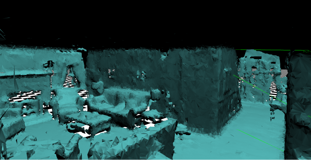
Example surface map produced by HoloLens

The next step after establishing a shared coordinate system is to use the HoloLens for obstacle detection and avoidance. The HoloLens has the ability to map surfaces in real time and position itself in that map (SLAM). Logic could be added to the HoloLens to consume this surface map and adjust pathing/setpoints to avoid these obstacles without reducing the overall compute/power budget of the Crazyflie itself.

Swarm Control and Manipulation

As a simple extension of the shared coordinate system (and what Bitcraze has been doing with TDoA and swarming lately) the HoloLens could be used to manipulate individual Crazyflies within a swarm through raycasting (the same technique used to gaze at, select and move specific holograms in the digital domain). Or perhaps a swarm could be controlled to move out of the way as a user passes through the swarm, and return to formation afterward.

Augmenting with Digital Content

All scenarios discussed thus far have dealt with using the HoloLens as an input and localization device, but its primary job is to project digital content into the real world. I can think of applications such as:

  • Games
    • Flying around through a digital obstacle course
    • First person shooter or space invaders type game (Crazyflie moves around to avoid user or fire rendered laser pulses at user, etc)
  • Diagnostic/development tools
    • Overlaying some diagnostic information (such as battery life) above the Crazyflie (or each Crazyflie in a swarm)
    • Set or visualize/verify the position of the LPS nodes in space
    • Visualize the position of the Crazyflie as reported by LPS, to observe error or drift in real time

Conclusion

There’s no shortage of interesting applications related to blending augmented reality with the Crazyflie, but there’s quite a bit of work ahead to get there. Keep an eye on the Bitcraze blog or the forums for updates and news on this effort.

I’d love to hear what ideas you have for combining augmented reality devices with physical devices like the Crazyflie. Leave a comment with thoughts, suggestions, or any other relevant work!

Here at the USC ACT Lab we conduct research on coordinated multi-robot systems. One topic we are particularly interested in is coordinating teams consisting of multiple types of robots with different physical capabilities.

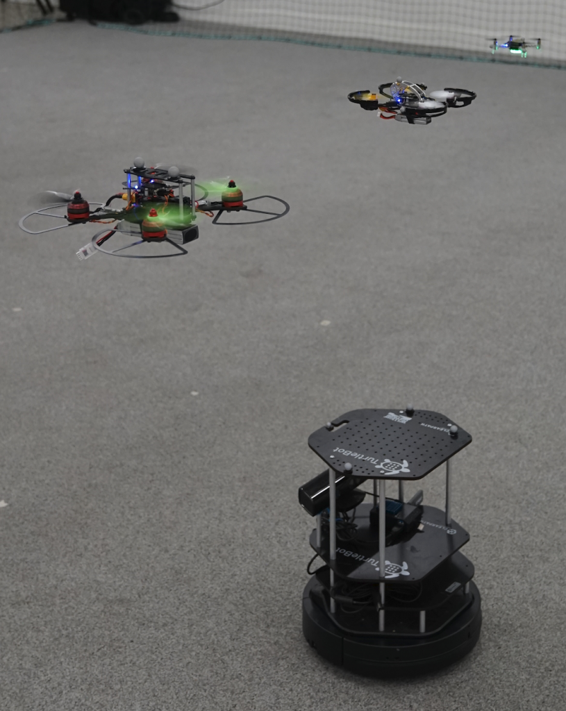
A team of three quadrotors all controlled with Crazyflie 2.0 and a Clearpath Turtlebot

Applications such as search and rescue or mapping could benefit from such heterogeneous teams because they allow for more flexibility in the choice of sensors and locomotive capability. A core challenge for any multi-robot application is motion planning – all of the robots in the team need to make it to their target locations efficiently while avoiding collisions with each other and the environment. We have recently demonstrated a scalable method for trajectory planning for heterogeneous robot teams utilizing the Crazyflie 2.0 as the flight controller for our aerial robots.

A Crazier Swarm

To test our trajectory planning research we wanted to assemble a team with both ground robots and multiple sizes of aerial robots. We additionally wanted to leverage our existing Crazyswarm software and experience with Crazyflie firmware to avoid some of the challenges of working with new hardware. Luckily for us the BigQuad deck offered a straightforward way to super-size the Crazyflie 2.0 and gave us the utility we needed.

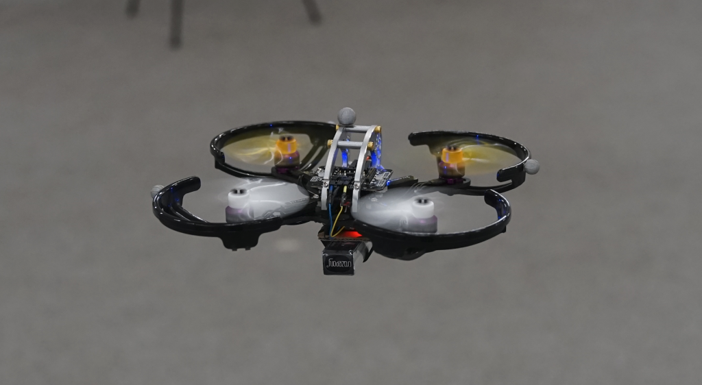
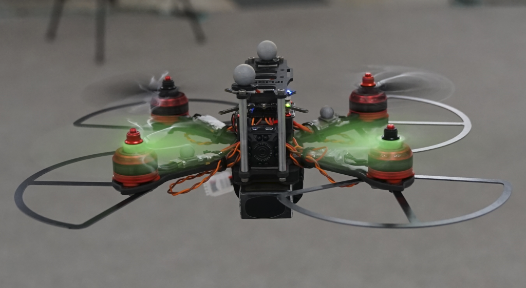
With the BigQuad deck and off-the-shelf components from the hobbyist drone community we built three super-sized Crazyflie 2.0s. Two of them weigh 120g (incl. battery) with a motor-to-motor size of 130mm, and the other is 490g (incl. battery and camera) with a size of 210mm.

120g, 130mm

490g, 210mm

We wanted to pick components that would be resistant to crashing while still offering high performance. To meet these requirements we ended up picking components inspired by the FPV drone racing community where both reliable performance and high-impact crashes are expected. Full parts lists for both platforms are available here

Integrating the new platforms into the Crazyswarm was fairly easy. We first had to re-tune the PID controller gains to account for the different dynamics of the larger platforms. This didn’t take too long, but we did crash a few times — luckily the components we chose were able to handle the crashes without any breakages. After tuning the platforms behave very well and are just as easy to work with as the original Crazyflie 2.0. We additionally updated the Crazyswarm package to be able to differentiate between BigQuad and regular Crazyflie types and those updates are now available for use by anyone!

In future work, we are excited to do hands-on experiments with a prototype of the CF-RZR. This new board seems like a promising upgrade to the CF 2.0 + BQD combination as it has upgraded components, an external antenna, and a standardized form factor. Hopefully we will see the CF-RZR as part of the Crazyswarm in the near future!

Mark Debord
Master’s Student
Automatic Coordination of Teams Laboratory
University of Southern California
Wolfgang Hönig
PhD Student
Automatic Coordination of Teams Laboratory
University of Southern California


This is a guest blog post written by Fred, the maintainer of the Android Crazyflie client and Java Crazyflie lib.

As a follow-up to last week’s blog post about the different Crazyflie clients, I would like to describe the current status of the Android client in a bit more detail.

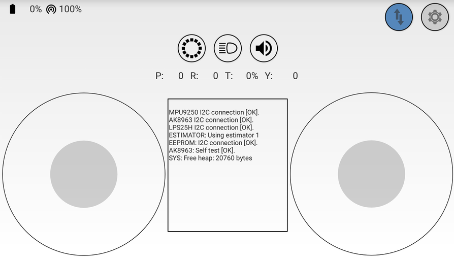
After more than a year, Version 0.7.0 of the Android client has been released last Friday (March 16). Most importantly this release fixes a very annoying UI bug that appeared on newer Android versions, where the on-screen joystick did not show up when the app was started for the first time. It also adds support for height hold mode when using the zRanger or Flow deck, it adds a console view (can be enabled in Settings -> App settings -> Show console) and also shows the link quality for BLE connections now. You can read the full changelog on Github. You can find the release in the Google Play Store and as an APK on GitHub.

Connection quality and console messages now work on a BLE connection

Apart from the obvious/visible new features and bug fixes, quite a lot has happened “under the hood”. Some parts of the code were cleaned up, refactored, decoupled, etc. This is still a work in progress though.

There is still plenty of stuff to do for future releases, especially in the realm of Bluetooth support. On the short list are:

  • Param/Log support for BLE connections
  • bootloading over BLE
  • support for Flow deck sequences

Admittedly there was almost no documentation for the Android client and some features are hidden (too well). In an effort to change that, I’ve started to document some features on the project’s Github wiki.

If you find bugs in the app, want to request a feature or see errors in the documentation, please open a GitHub issue.

If you are interested in the development of the Crazyflie Android client and want to get involved, let me know. The fastest way to get new features added or bugs fixed is to contribute a pull request.

Last but not least, I’d like to thank the Bitcraze team for creating and developing the Crazyflie and amazing new decks. Maintaining the Crazyflie Android client is still one of my favorite past times. :)

This week we have a guest blog post by Ben, enjoy!

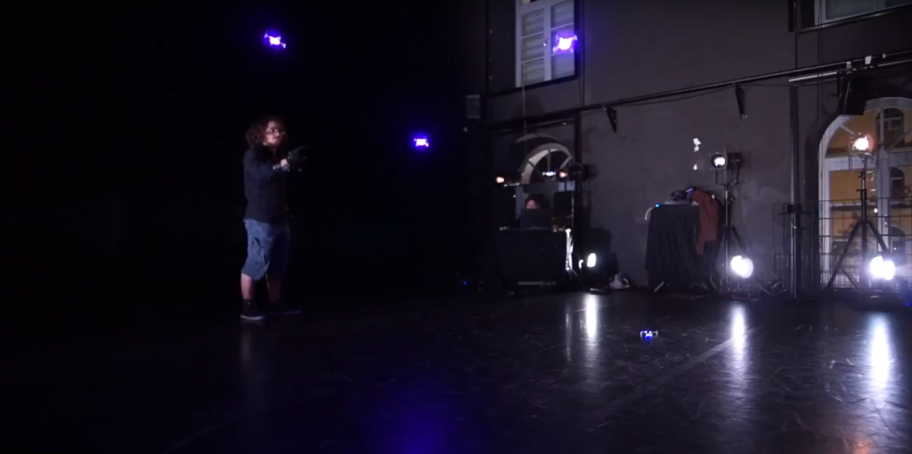
I’m Ben Kuperberg and i’m a digital artist, artist-friendly software developer and orchestra conductor. Being a juggler, I’ve decided to focus some of my work on the intersection between juggling and technology, and i’ve since been working more and more with jugglers, my last project being “Sphères Curieuses” from Le Cirque Inachevé, created by Antoine Clée. While the whole project is not focused on drones, a part of it involves synchronized flight of multiple drones and precise human interaction with those drones. Swarm flight is something already out there and some solutions already exist but the context of this project added some challenges to it.

Most work on drone swarms have been done by research group or school. They use high-grade expensive motion-capture system able to track precisely the drones and able to assign their absolute positions. While the quality of the result is undeniable, it’s not fit for stage shows : the setup is taking a lot of time which we can’t always have when the show is on the road. Moreover, the mocap system is too invasive for the stage if you want to be able to “hide” a bit the technology and let the spectator focus on what the artist wants you to see. Not to mention it costs an arm and a leg and Antoine needs both to juggle.

So we had to find other ways to be able to track multiple drones. That’s when we found out the [amazing] team at Bitcraze was working on the TDoA technology, which allows precise-enough tracking of a virtually unlimited amount drones, at reduced cost and with a fast and clean setup.

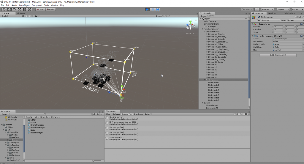
After some work we managed to have a first rough version of our swarm server made by Maxime Agor that allowed to connect and move multiple drones using the TDoA system, controlled from a Unity application.

While we were able to present a decent demo with this system, we were facing a major problem of reactivity. When working with artists and technology, reactivity is a key component to creativity. Because it can be frustrating and tense to stop each 2 minutes to make changes or fix problems. My first priority was therefore to prepare and design softwares that will allow me to spend most of the “creation time” on the actual creation aspect and not on technical parts. It is also essential that the artist performing in front of the audience can entirely focus on the performance and by fully confident in this technology. The last challenge is that as I focus my work on the creation and not touring, all my work needs to be easily understood and modified by both the artists and the technicians who will take over my work for the tour.

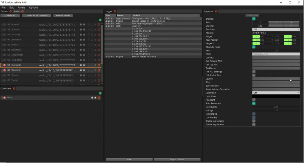
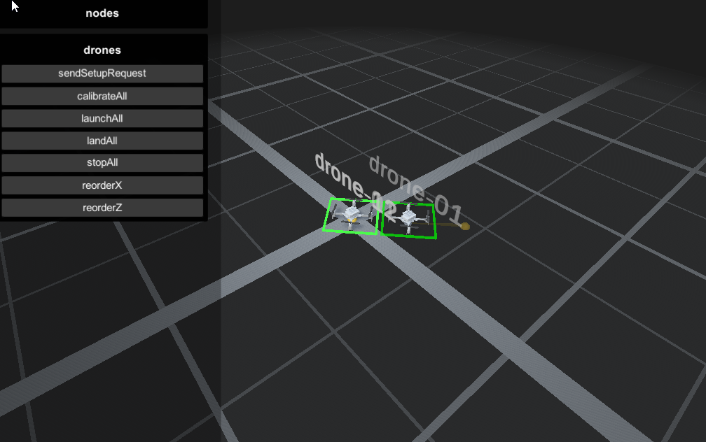
With all of that in mind, I decided to create a software with a high-end user interface called “La Mouche Folle” (« The Crazy Flie » in french) that allows to control multiple drones and have an overview of all the drones, their battery/charging/alert states, auto-connect / auto-reboot features, external control via OSC, and a Unity client to view and actually decide how to move the drones. All my work is open-source, so you can find the software on github.

There only is a Windows release for now but it should compile just fine on OSX and Linux, the software is made with JUCE, depends on OrganicUI and lib-usb. Feel free to contact me if you want more information on the software. Many thanks Wolfgang Hoenig for the support and the great work on the crazyflie cpp library i’m relying on.

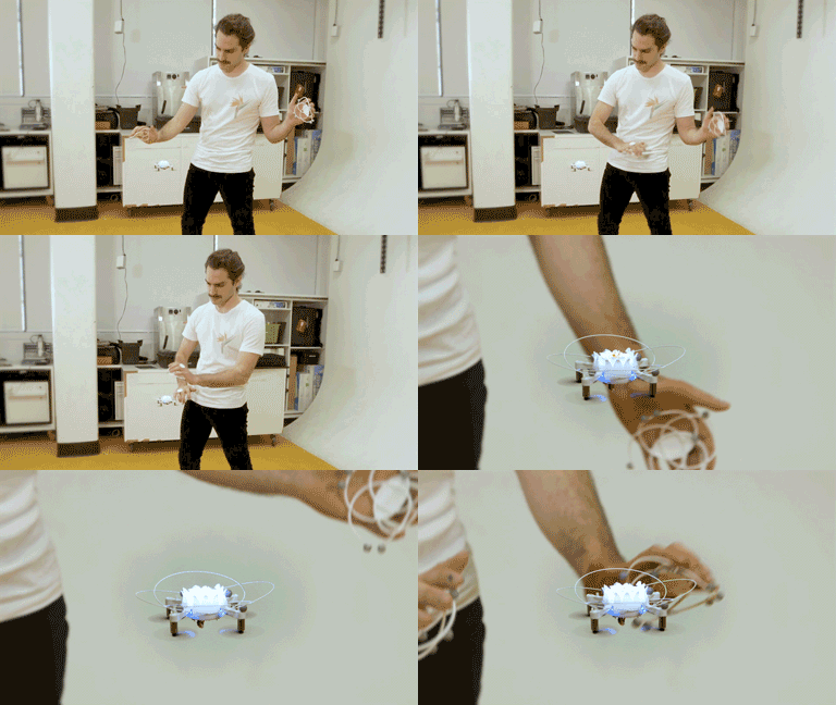
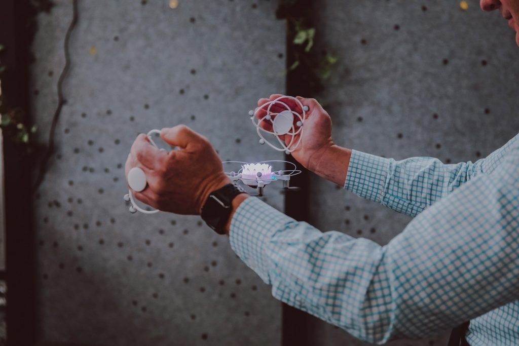
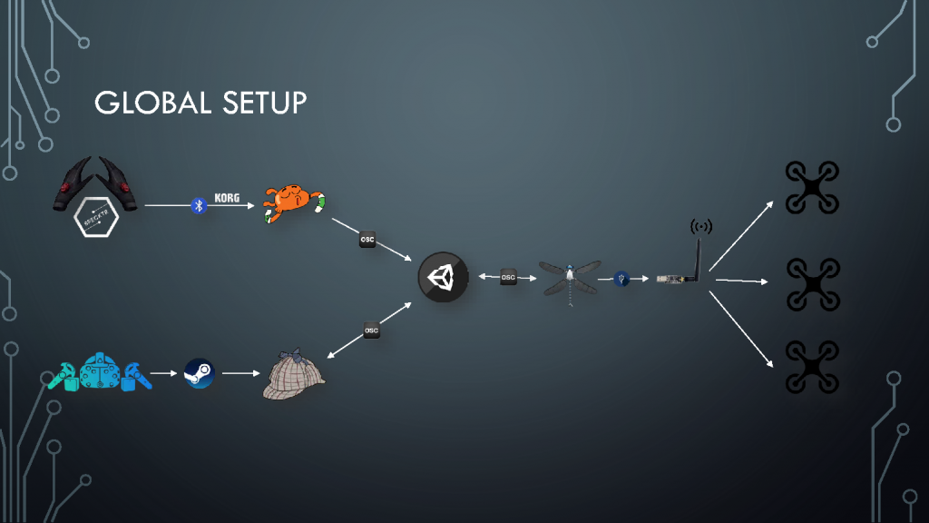
So this is the basic setup of our project, but we needed more than that to control the drone. We wanted to be able to control them in the most natural way possible. We quickly decided to go with glove-base solutions, and have been working with Specktr to get our hands – pun intended – on developer versions of the glove. The glove is good but can’t give us absolute position of the hand, so we added HTC Vive trackers with the lighthouse technology and then were able to get both natural hand control and sub-millimeter precision of the tracked hand.

Then it was a matter of connecting everything together : for other projects for Theoriz Studio, I already developed MrTracker (used in the MixedReality project) that acts as a middleware between the Vive trackers and Unity.

I used Chataigne to easily connect and route the Specktr Glove data to Unity as well so we would have maximum flexibility to switch hardware or technology without breaking whole setup if we needed to.

 
A video of the final result


In the past years, i’ve come to work on a lot of different projects, with different teams, which i like very much, because each project leads to discover new people, new ways of working and new challenges to overcome. I’m having a great time working on this project and especially sharing everything with the guys at Bitcraze and the community, everyone has been so cool and nice. I’ve planned to go at the Bitcraze studios to work for few weeks with them and i’m sure it’ll be a great experience !

Modular robots can adapt and offer solutions in emergency scenarios, but self-assembling on the ground is a slow process. What about self-assembling in midair?

In one of our recent work in GRASP Laboratory at University of Pennsylvania, we introduce ModQuad, a novel flying modular robotic structure that is able to self-assemble in midair and cooperatively fly. This work is directed by Professor Vijay Kumar and Professor Mark Yim. We are focused on developing bio-inspired techniques for Flying Modular Robots. Our main interest is to develop algorithms and controllers for self-assembling modular robots that can dock in midair.

In biological systems such as ant or bee colonies, collective effort can solve problems not efficient with individuals such as exploring, transporting food and building massive structures. Some ant species are able to build living bridges by clinging to one another and span the gaps in the foraging trail. This capability allows them to rapidly connect disjoint areas in order to transport food and resources to their colonies. Recent works in robotics have been focusing on using swarm behaviors to solve collective tasks such as construction and transportation.Docking modules in midair offers an advantage in terms of speed during the assembly process. For example, in a building on fire, the individual modules can rapidly navigate from a base-station to the target through cluttered environments. Then, they can assemble bridges or platforms near windows in the building to offer alternative exits to save lives.

ModQuad Design

The ModQuad is propelled by a quadrotor platform. We use the Crazyflie 2.0. The vehicle was chosen because of its agility and scalability. The low-cost and total payload gives us an acceptable scenario for a large number of modules.

Very light-weight carbon fiber rods connected by eight 3-D printed ABS connectors form the frame. The frame weight is important due to tight payload constraints of the quadrotor. Our current frame design weighs 7g about half the payload capability. The module geometry has a cuboid shape as seen in the figure below. To enable rigid attachments between modules, we include a docking mechanism in the modular frame. In our case, we used Neodymium Iron Boron (NdFeB) magnets as passive actuators.

Self-Assembling and Cooperative Flying

ModQuad is the first modular system that is able to self-assemble in midair. We developed a docking method that accurately aligns and attaches pairs of flying structures in midair. We also designed a stable decentralized modular attitude controller to allow a set of attached modules to cooperatively fly. Our controller maximizes the use of the rotor forces by generating the maximum possible moment.

In order to allow the flying structure to navigate in a three dimensional environment, we control thrust and attitude to generate vertical and horizontal translations, and rotation in the yaw angle. In our approach, we control the attitude of the structure in a decentralized manner. A modular attitude controller allows multiple connected robots to stably and cooperatively fly. The gain constants in our controller do not need to be re-tuned as the configurations change.

In order  to dock pairs of flying structures in midair, we propose to have two flying structures: the first one is hovering and waiting, meanwhile the second one is performing a docking action. Both, the hovering and the docking actions are based on a velocity controller. Using a velocity controller, we are able to dock multiple robots in midair. We highlight that docking robots in midair is one of the fastest ways to assemble structures because the building units can rapidly move and dock in three dimensional environments. The docking system and control has been validated through multiple experiments.

Our system takes advantage of robot swarms because a large number of robots can construct massive structures.

This work was developed by:

David Saldaña, Bruno Gabrich, Guanrui Li, Mak Yim, and Vijay Kumar.

Additional resources at:

http://kumarrobotics.org/

http://www.modlabupenn.org/

http://davidsaldana.co/

Grasping objects is a hard task that usually implies a dedicated mechanism (e.g arm, gripper) to the robot. Instead of adding extra components, have you thought about embedding the grasping capability to the robot itself? Have you also thought about whether we could do it flying?

In the GRASP Laboratory at the University of Pennsylvania, we are concerned about controlling robots to perform useful tasks. In this work, we present the Flying Gripper! It is a novel flying modular platform capable of grasping and transporting objects with the help of multiple quadrotors (crazyflies) working together. This research project is coordinated by Professor Mark Yim and Professor Vijay Kumar, and led by Bruno Gabrich (PhD candidate) and David Saldaña (Postdoctoral researcher).


Inspiration in Nature

In nature, cooperative work allows small insects to manipulate and transport objects often heavier than the individuals. Unlike the collaboration in the ground, collaboration in air is more complex especially considering flight stability. With this inspiration, we developed a platform composed of four cooperative identical modules where each is based on a quadrotor (crazyflies) within a cuboid frame with a docking mechanism. Pair of modules are able to fly independently and physically connect by matching their vertical edges forming a hinge. Four one degree of freedom (DOF) connections results in a one DOF four-bar linkage that can be used to grasp external objects. With this platform we are able to change the shape of the flying vehicle during flight and use its own body to constrain and grasp an object.

Flying Gripper Design and Motion

In the proposed modular platform, we use the Crazyflie 2.0. Its battery life lasts around seven minutes, though in our case battery life time is reduced due to the extra weight. The motor mounting was modified from the standard design, we tilted the rotors 15 degrees. This was necessary as more yaw authority was required to enable grasping as a four-bar. However, adding this tilt reduces the lifting thrust by 3%. Axially aligned cylindrical Neodymium Iron Boron (Nd-FeB) magnets, with 1/8″ of diameter and 1/4″ of thickness are mounted on each corner enabling edge-to-edge connections. The cylindrical magnets have mass of 0.377g and are able to generate a force of 0.4 kg in a tangential connection between two of the same magnets. This forms a strong bond when two modules connect in flight. Note that the connections are not rigid – each forms a one DOF hinge.

The four attached modules results in a one DOF four bar linkage in addition to the combined position and attitude of the conglomerate. The four-bar internal angles are controlled by controlling the yaw attitude of each module. For example, two modules rotate clockwise and other two modules rotate counter-clockwise in a coordinated manner.


Grasping Objects

Collaborative manipulation in air is an alternative to reduce the complexity of adding manipulator arms to flying vehicles. In the following video we are able to see the Flying Gripper changing its shape in midair to accomplish the complex task of grasping a wished coffee cup. Would you like some coffee delivery?


This work was developed by:

Bruno Gabrich, David Saldaña, Vijay Kumar and Mark Yim

Additional resources at:

http://kumarrobotics.org/

http://www.modlabupenn.org/

This week’s Monday post is a guest post written by members of the Computer Science and Artificial Intelligence Lab at MIT.

One of the focuses of the Distributed Robotics Lab, which is run by Daniela Rus and is part of the Computer Science and Artificial Intelligence Lab at MIT, is to study the coordination of multiple robots. Our lab has tested a diverse array of robots, from jumping cubes to Kuka youBots to quadcopters. In one of our recent projects, presented at ICRA 2017, Multi-robot Path Planning for a Swarm of Robots that Can Both Fly and Drive, we tested collision-free path planning for flying-and-driving robots in a small town.

Robots that can both fly and drive – in particular wheeled drones – are actually somewhat of a rarity in robotics research. Although there are several interesting examples in the literature, most of them involve creative ways of repurposing the wings or propellers of a flying robot to get it to move on the ground. Since we wanted to test multi-robot algorithms, we needed a robot that would be robust, safe, and easy to control – not necessarily advanced or clever. We decided to put an independent driving mechanism on the bottom of a quadcopter, and it turns out that the Crazyflie 2.0 was the perfect platform for us. The Crazyflie is easily obtainable, safe, and (we can certify ourselves) very robust. Moreover, since it is open-source and fully programmable, we were able to easily modify the Crazyflie to fit our needs. Our final design with the wheel deck is shown below.

A photo of the Crazyflie 2.0 with the wheel deck.

A model of the Crazyflie 2.0 with the wheel deck from the bottom

The wheel deck consists of a PCB with a motor driver; two small motors mounted in a carbon fiber tube epoxied onto the PCB; and a passive ball caster in the back. We were able to interface our PCB with the pins on the Crazyflie so that we could use the Crazyflie to control the motors (the code is available at https://github.com/braraki/crazyflie-firmware). We added new parameters to the Crazyflie to control wheel speed, which, in retrospect, was not a good decision, since we found that it was difficult to update the parameters at a high enough rate to control the wheels well. We should have used the Crazyflie RealTime Protocol (CRTP) to send custom data packages to the Crazyflie, but that will have to be a project for another day.
The table below shows the mass balance of our miniature ‘flying car.’ The wheels added 8.3g and the motion capture markers (we used a Vicon system to track the quads) added 4.2g. So overall the Crazyflie was able to carry 12.5g, or ~44% of its body weight, and still fly pretty well.


Next we measured the power consumption of the Crazyflie and the ‘Flying Car.’ As you can see in the graph below, the additional mass of the wheels reduced total flight time from 5.7 minutes to 5.0 minutes, a 42-second or 12.3% reduction.

Power consumption of the Crazyflie vs. the ‘Flying Car’


The table below shows more comparisons between flying without wheels, flying with wheels, and driving. The main takeaways are that driving is much more efficient than flying (in the case of quadcopter flight) and that adding wheels to the Crazyflie does not actually reduce flying performance very much (and in fact increases efficiency when measured using the ‘cost of transport’ metric, which factors in mass). These facts were very important for our planning algorithms, since the tradeoff between energy and speed is the main factor in deciding when to fly (fast but energy-inefficient) versus drive (slow but energy-efficient).

Controlling 8 Crazyflies at once was a challenge. The great work by the USC ACT Lab (J. A. Preiss, W. Hönig, G. S. Sukhatme, and N. Ayanian. “Crazyswarm: A Large Nano-Quadcopter Swarm,” ICRA 2017. https://github.com/USC-ACTLab/crazyswarm) has made our minor effort in this field obsolete, but I will describe our work briefly. We used the crazyflie_ros package, maintained by Wolfgang Hönig from the USC ACT Lab, to interface with the Crazyflies. Unfortunately, we found that a single Crazyradio could communicate with only 2 Crazyflies at a time using our methods, so we had to use 4 Crazyradios, and we had to make a ROS node that switched between the 4 radios rapidly to send commands. It was not ideal at all – moreover, we had to design 8 unique Vicon marker configurations, which was a challenge given the small size of the Crazyflies. In the end, we got our system to work, but the new Crazyswarm framework from the ACT Lab should enable much more impressive demos in the future (as has already been done in their ICRA paper and by the Robust Adaptive Systems Lab at Carnegie Mellon, which they described in their blog post here).

We used two controllers, an air and a ground controller. The ground controller was a simple pure pursuit controller that followed waypoints on ground paths. The differentially steered driving mechanism made ground control blissfully simple. The main challenge we faced was maximizing the rate at which we could send commands to the wheels via the parameter framework. For aerial control, we used simple PID controllers to make the quads follow waypoints. Although the wheel deck shifted the center of mass of the Crazyflie, giving it a tendency to slowly spin in midair, overall the system worked well given its simplicity.

Once we had the design and control of the flying cars figured out, we were able to test our path planning algorithms on them. You can see in the video below that our vehicles were able to faithfully follow the simulation and that they transitioned from flying to driving when necessary.

Link to video

Our work had two goals. One was to show that multi-robot path planning algorithms can be adapted to work for vehicles that can both fly and drive to minimize energy consumption and time. The second goal was to showcase the utility of flying-and-driving vehicles. We were able to achieve these goals in our paper thanks in part to the ease of use and versatility of the Crazyflie 2.0.