Category: Lighthouse

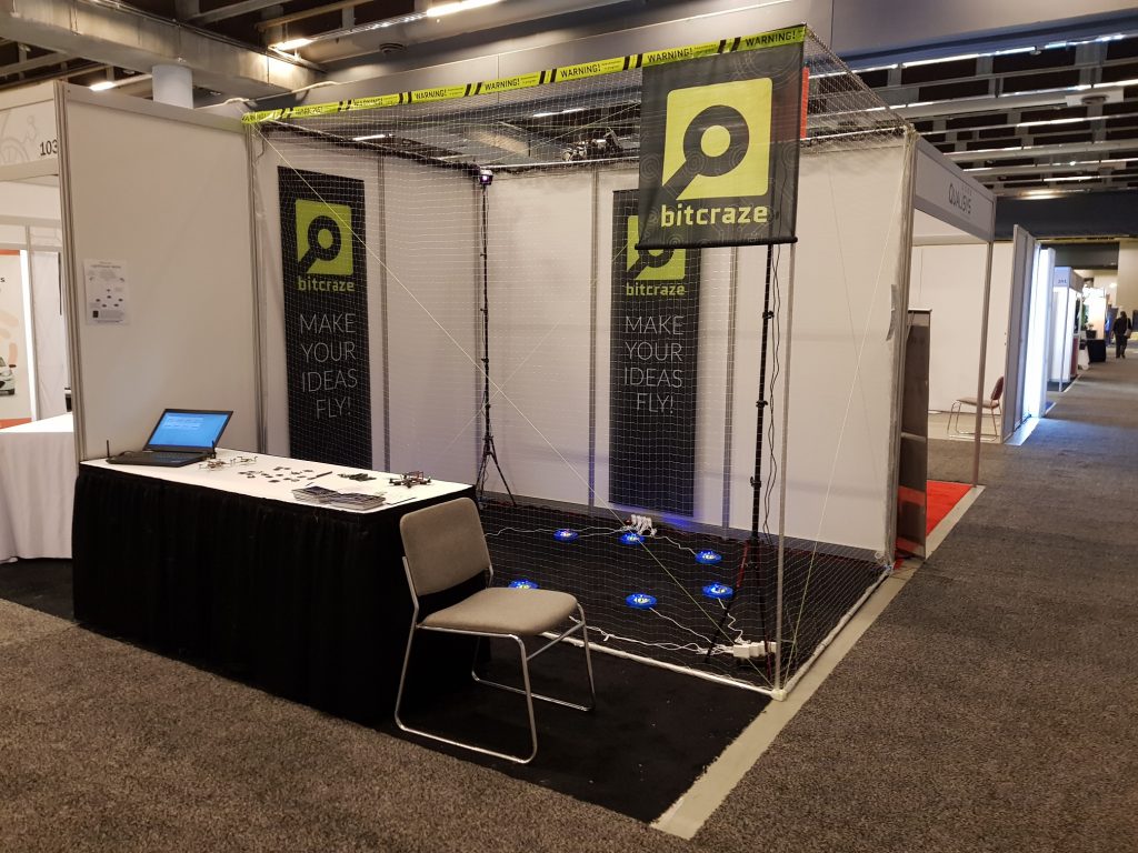
Only a week left until we stand in our ICRA booth in Montreal and give you a gimps of what we do here at Bitcraze. As we have been writing about earlier we are aiming to run a fully automated demo. We have been fine tuning it over the last couple of days and if something unpredictable doesn’t break it, we think it is going to be very enjoyable. For those that are interested in the juicy details check out this informative ICRA 2019 page, but if you are going to visit, maybe wait a bit so you don’t get spoiled.

Apart from the demo we are also going to show our products as well as some new things we are working on. The brand new things include:

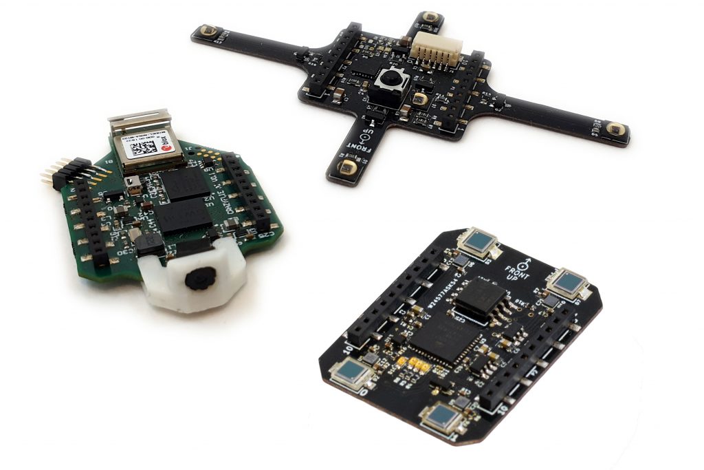
AI-deck, Active marker deck and Lighthouse-4 deck
  • AI-deck: This is a collaborative product between GreenWaves Technologies, ETH Zurich and Bitcraze. It is based on the PULP-shield that the Integrated and System Laboratory has designed. You can read more about it in this blog post. The difference with the PULP-shield is that we have added a ESP32, the NINA-W102 module, so that video can be streamed over WiFi. This we hope will ease development and add more use cases.
  • Active marker deck: Another collaboration, but this time with Qualisys. This will make tracking with their motion capture cameras easier and better. Some more details in this blog post. Qualisys will have the booth just next to us were it will be possible to see it in a live demo!
  • Lighthouse-4 deck: Using the Vive lighthouse positioning system this deck adds sub-millimeter precision to the Crazyflie. This is the deck used in the demo and could become the star of the show.

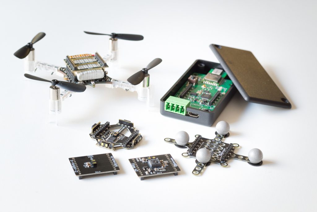
Adding to the above we will of course also display our recently released products:

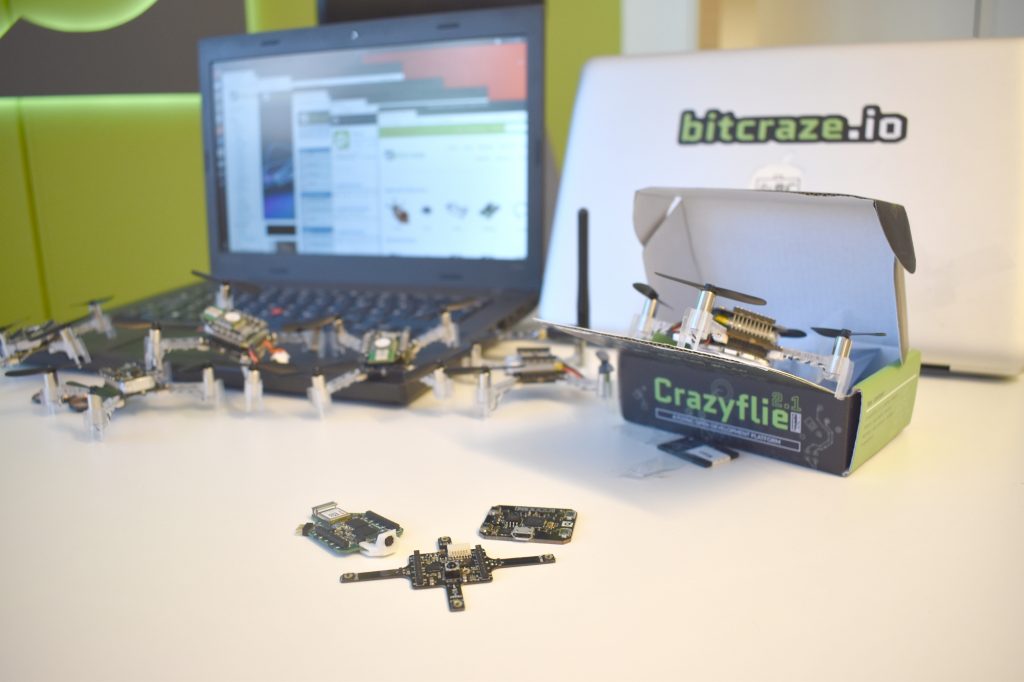
  • Crazyflie 2.1: The Crazyflie 2.1 is an improvement of the Crazyflie 2.0 but keeping backward capability.
    • Better radio performance and external antenna support: With a new radio power amplifier we’ve improved the link quality and added support for dual antennas (on-board chip antenna and external antenna via u.FL connector)
    • Better power button: We’ve gotten feedback that the power button breaks too easily, so now we’ve replaced with a more solid alternative.
    • Improved battery cable fastening: To avoid weakening of the cables over time they are now run through a cable relief.
    • Improved sensors: To make the flight performance better we’ve switched out the IMU and pressure sensor. The new Crazyflie uses the drone specialized sensor combo BMI088 and BMP388 by Bosch Sensortech.
  • Flow deck v2: The Flow deck v2 has been upgraded with the new ST VL53L1x which increases the range up to 4 meters
  • Z-ranger deck v2: The Z-ranger v2 deck has been upgraded with the new ST VL53L1x which increases the range up to 4 meters
  • Multi-ranger deck: The Multi-ranger deck adds VL53L1x sensors in all directions for mapping and obstacle avoidance.
  • MoCap marker deck: The motion capture deck with support for easily attachment of passive markers for motion capture camera tracking.
  • Roadrunner: The Roadrunner is released as early access and the hardware is basically a Crazyflie 2.1 without motors and up to 12V input power. This enables other robots or system to use the loco positioning system.

You can find us in booth 101 at ICRA 2019 (in Montral, Canada), May 20 – 22. Drop by and say hi, check out the products & demo and tell us what you are working on. We love to hear about all the interesting projects that are going on. See you there!

As mentioned earlier, we will be attending ICRA 2019 and have started to work on the demo that we will run in our booth. The main features we are going to show this time are the Lighthouse positioning deck and the Crazyflie 2.1.

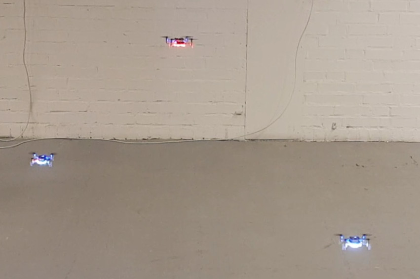
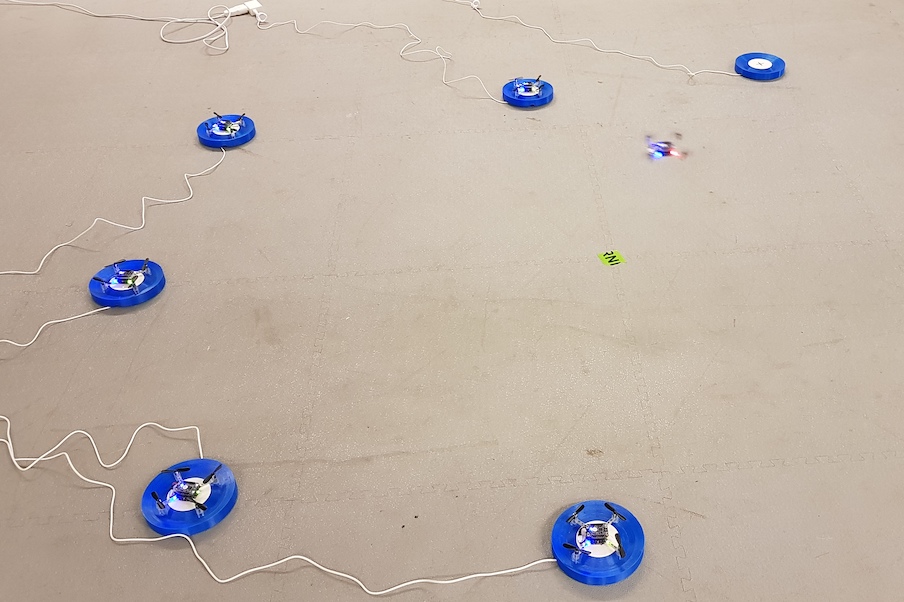
One Crazyflie flying and 5 re-charging on their pads

Running a demo with flying Crazyflies at a conference, usually means a lot of work with changing and charging batteries, starting demos and so on. This takes time and leads to less time to talk to all the interesting people that visit our booth. This year we are aiming at making the demo as fully automated as possible. We will have 8 Crazyflie 2.1 with Lighthouse and Qi charger decks, each with a charging pad. A computer will orchestrate the Crazyflies and make sure one is flying at all times while the others re-charge their batteries. When the battery of the flying Crazyflie is depleted it goes back to its pad while another one takes over.

Most of the functionality is implemented in the Crazyflie firmware and it is pretty much autonomous after the trajectory is started. It will fly the trajectory over and over until it is low on battery, when it goes back to where it started from for recharging. Even though the Lighthouse positioning is very good, it sometimes slips off the charging pad when landing, so we have added a reposition feature to take off again and land if it is not charging after landing.

The orchestration computer (we call it the Control tower) is just keeping track of the state of the flying copter and starts a new one when the flying one goes back the the pad.

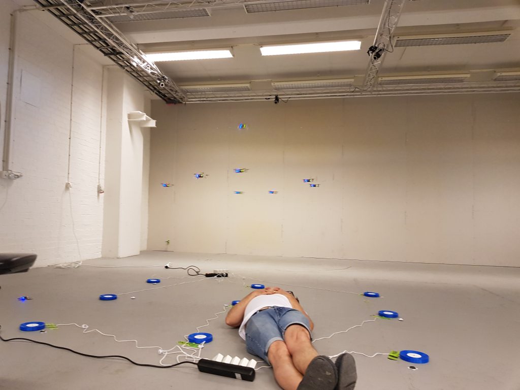
We are reusing the spiral trajectory from IROS last year and it has the property that it is possible to run up to 4 copters at the same time without colliding, if they are started at the correct times. There is a swarm feature in the Control tower that runs up to 4 Crazyflies with continuous replacements. The chargers are not fast enough to keep it going and it does not work as expected every time, but it is exciting with a few more Crazyflies buzzing around!

There are some bits and pieces left to implement, like crash detection, but the demo is mostly functional. If you want to play with the (slightly hackish) code, it is available at https://github.com/bitcraze/crazyflie-firmware-experimental/tree/icra-2019

You can find us in booth 101 at ICRA 2019, May 20 – 22. Drop by and say hi, check out the demo and tell us what you are working on. We love to hear about all the interesting projects that are going on. See you there!

We attended the Innovation Week at Lund University on Thursday last week. Primarily we wanted to talk to students and possibly find future colleagues (yes, we are hiring) but it was also a good opportunity to get some demo time with the Lighthouse positioning system.

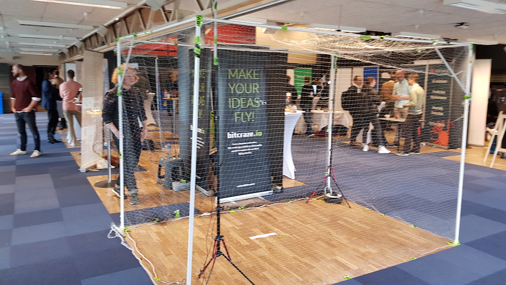
The demo setup. A bit blurry, sorry!

As mentioned in an earlier blog post, we are going to ICRA in May and we have started to think about what to demo. The main feature will of course be the Lighthouse deck. The setup at Innovation week also served the purpose of a first iteration for the ICRA setup.

We reused an old cage that we created for another fair a couple of years ago, built from a garden tent. It turned out to be fairly wobbly and a bit heavy (steel tubing) considering we will bring it in our luggage to Canada. We probably have to rethink the construction a bit and see if we can change to aluminium.

We put the Lighthouse base stations on tripods, which worked like a charm in our flight lab. We found that we had a lot of problems calibrating the system, not to mention flying the Crazyflie, at the Innovation week fair though. It turned out that the floor was not as stable as one might expect and that the tripods were swaying when people walked by. We solved the problem by adding a tube to the top of tripod that was pushed against the ceiling and thus minimizing the movement. Experience from the real world is always useful!

The general idea for the demo at ICRA is to automate as much as possible to give us more time with visitors. With the high precision of the Lighthouse system, it should be easy to land the Crazyflies on Qi chargers to avoid changing batteries. We hope to set up 6-8 Crazyflies where one is always flying while the others are charging, and have the possibility to temporarily fly more Crazyflies for small swarms. It is still just ideas and we will not see the end result until we are at ICRA, but it will be fun to build!

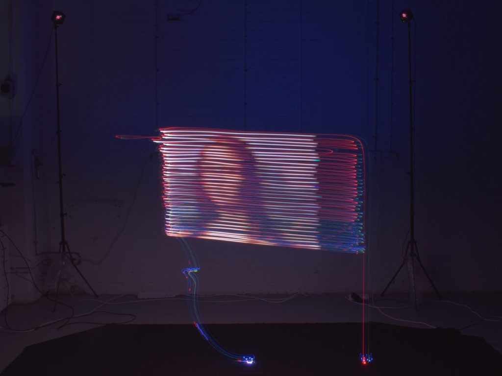
Last week we posted about painting with the Lighthouse deck. This week we continue on the same track but add a new dimension, all in our “let’s try this crazy idea” spirit. So last Friday, after having a lot of fun painting with the Crazyflie led-ring using long exposure photo and the Lightouse deck for positioning, we had one extra crazy idea. Can we use the Crazyflie to show a raster image, very much like the way a CRT monitor works by sweeping line by line and displaying the pixel color one by one, using the led-ring? Unfortunate we did not have enough time that day…

However the idea was so intriguing that Kristoffer couldn’t stop himself from writing a prototype script during the week-end. So last Monday, just after publishing the blog post, we went to the flight arena and tried it. After a couple of trial and error we found a display algorithm that showed a pretty good result:

Crazy-Lisa

The source for this image is this very low resolution Mona Lisa:

It was a very fun experiment, it is magic to see the Crazyflie going back and forth blinking for ~3 minutes, click on the camera and see the resulting picture. It is also a really nice way to observe the current state of the lighthouse positioning. The lines are spaced by about 3 cm and the Crazyflie is controlled using the PID controller. The controller do a decent job of keeping the Crazyflie in lines and the space seems a little bit ’tilted’.

If you are curious or if you want to try by yourself, we pushed the script in the Crazyflie-lib-python example folder.

As a side note, we will be exhibiting at the ICRA 2019 conference May 20-24, 2019 in Montreal, Canada. We will running demo of the LPS and Lighthouse (though I am not sure we can print long exposure picture, this is not so exciting to look in real-time :). We hope you would like to come and meet us there!

Last week we blogged about the early release version of the lighthouse deck and showed a nice push-around demo of the Crazyflies using the Vive controller. Now we wanted to push the system even further, by making a Lighthouse Painting!

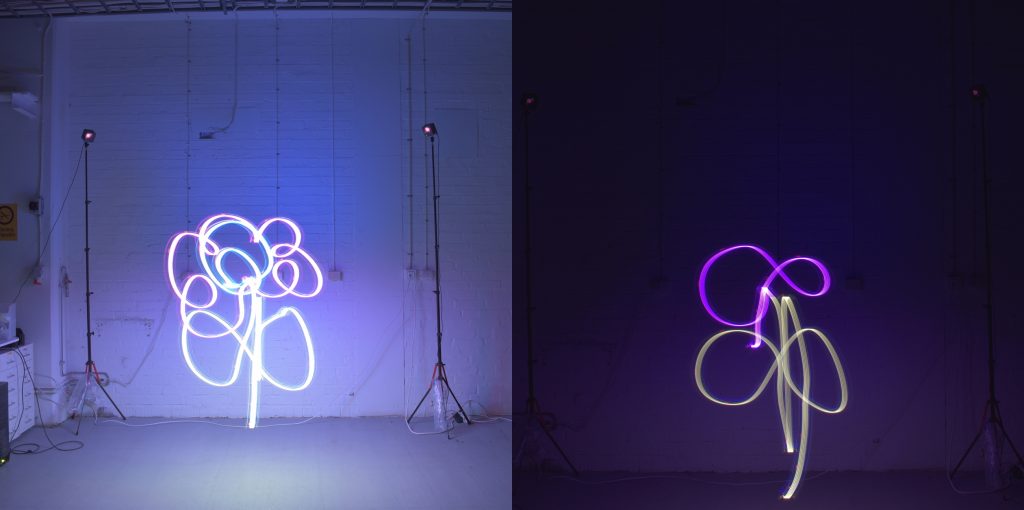
We started by adding a LED-ring deck on the bottom of the CrazyFlie 2.1 with the lighthouse deck attached to the top. We were able to access the input of the track pad of the Vive controller and link it to a specific color / hue value. The LED ring can display any color possible in the RGB range, so in theory, you could paint in whatever color you like. For now, the brightness was fixed, but this could be easily added to the demo script as well.

To capture the light trace, we needed to make a long-exposure image, therefore, the flight arena need to stay completely dark. Luckily, this was easy to do for us since we do not have any windows in our new testing arena. Our camera is the Canon D5600 with a manually controlled shutter time setting selected (press to open the shutter and press again to close the shutter). The aperture setting was set at F-22. Nevertheless, this is very depended on the environment, so we had to do some trial-and-error in order to get this parameter right.

Aperture too wide… perfect!

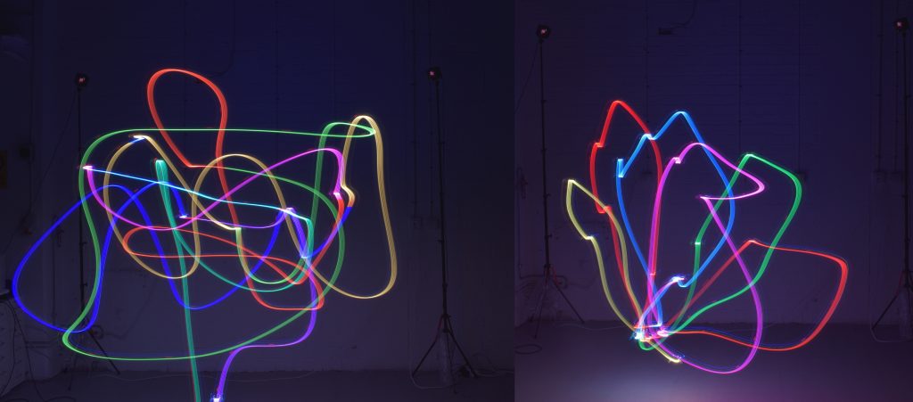
Once we had the set-up finished, we made several long exposure photo paintings with one person controlling the camera and another painting the picture into thin air. Of course, the artist would need to imagine its creation, as we were not able to see the result until after the picture was taken. Also, big gestures were required in order to complete the painting, as the Crazyflie’s and the Vive controller’s movements were synced 1:1, so adding some multiplication factor would come in handy. Nonetheless, the results were amazing.

Some nice examples of a single crazyflie flying based on the Vive’s position, changing color based on the trackpad

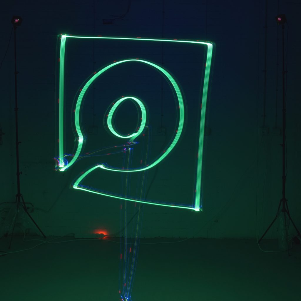
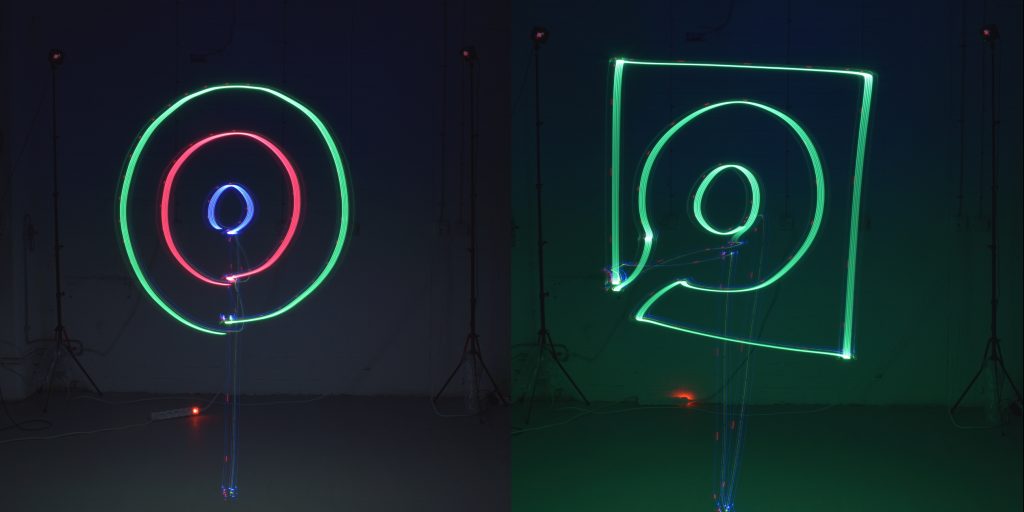
We took it even further, by making the Crazyflie fly a predefined trajectory and planned color scheme without the Vive controller. First, it flew three concentric circles in green, red and blue with the high level commander with the PID controller setting. But, the circles would probably be closed-off more properly with the Mellinger controller setting. We also were able to reproduce the Bitcraze logo in the same fashion. In both long-exposure photos, it still possible to see the Crazyflie, as it is still traceable due to its routine LED functionality, so you can easily observe where it took off, and where it flew in between shapes.

The Crazyflie flying a predefined trajectory in several shapes

The demo python scripts of the above flights can be found here:

An we also took a video of the Bitcraze logo being drawn. The mobile phone camera had some problems focusing in the dark, but it gives a good idea of how things works:

We have just released the Crazyflie Lighthouse deck as Early Access! It is now available in our web store.

The lighthouse deck allows the Crazyflie to estimate its position using the HTC Vive tracking base-station normally used for Virtual Reality. The positioning is done by tracking the timing of rotating infra-red laser beams emitted from the base-stations. This system has the advantages of having a very good precision and of allowing the Crazyflie to acquire its position autonomously: once the Crazyflie knows the position and orientation of the base-station, it can calculate its own position without the help of any external systems.

The release as Early Access means that we have finished the hardware and we are confident that the hardware is working properly. Though we have not yet finished all the software and firmware, by releasing the hardware early we can get the hardware into the hands of users quickly to try it out. In return we hope we can get some help making the software better.

Current state

  • The Crazyflie can calculate its position from the received Vive Base-Station V1 signals.
  • Direct line of sight should be kept to both base-stations. The Lighthouse deck has 4 receivers so in the future it will be possible to get a position from seeing only one base station.
  • Base-Station V2 support is still being worked-on, it will only require a software update.
  • The Base-station position is hard-coded in the Crazyflie and found using SteamVR. Ideally this should be sent from the ground and the Crazyflie should calculate the positions of the Base-Stations automatically.
  • The previous point means that a full VR system or at least two base stations and a controller or tracker is required to setup the system. In the future we hope to setup the system with only a Crazyflie and two base stations.
  • Since this version of the deck only has horizontal sensors, it is important that the base-stations are placed above the flight space and the Crazyflies should fly ~40cm bellow the base-stations

As long as the deck is in early access, the main documentation will be the lighthouse positioning page in the wiki. This page is going to be updated a lot in the near future and will track the progress in development.

Demo

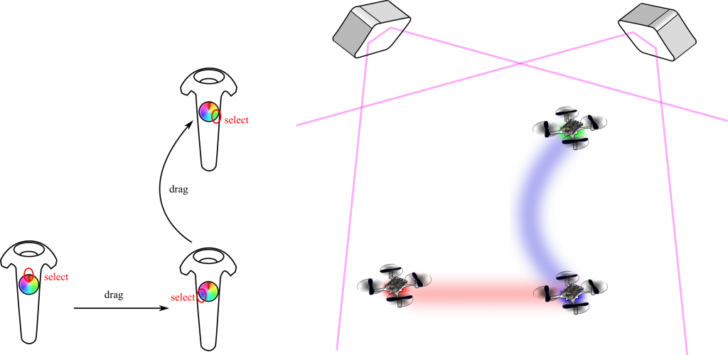
We have written a small demo script that allows to set the position of the Crazyflie using a Vive controller. It is a good demo to experiment with the precision of the system and the ability to mix VR and Crazyflie since they are in the same tracking space:

In this demo, a python script connects to two Crazyflies and acquire the controller position using OpenVR and makes the Crazyflies take-off above the controller. Then, when the controller trigger is pushed, the setpoint to the closest Crazyflie is changed to follow the controller movement, the Crazyflies are flying autonomously only getting position setpoints from the python script. The position estimation and control is handled onboard.

We are pretty excited by this release since we think this positioning technology will be very useful for a lot of use-case. Let us know what you think and do not hesitate to contribute if you want to improve the system :).

In this blog post we will describe one of the demos we were running at IROS and how it was implemented. Conceptually this demo is based on the same ideas as for ICRA 2017 but the implementation is completely new and much cleaner.

The demo is fully autonomous (no computer in the loop) but it requires an external positioning system. We flew it using either the Loco Positioning System or the prototype Lighthouse system.
A button has been added to the LPS deck to start the demo. When the button is pressed the Crazyflie waits for position lock, takes off and repeats a predefined spiral trajectory until the battery is out, when it goes back to the door of the cage and lands.
For some reason we forgot to shoot a video at IROS so a reproduced version from the (messy) office will have to do instead, imagine a 2×2 m net cage around the Crayzflie.

Implementation

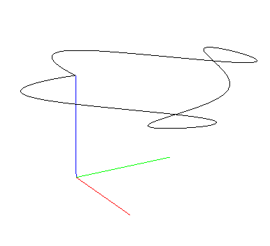
As mentioned in an earlier blog post the demo uses the high level commander originally developed by Wolfgang Hoenig and James Alan Preiss for Crazyswarm. We prototyped everything in python (sending commands to the Crazyflie via Crazyradio) to quickly get started and design the demo . Designing trajectories for the high level commander is not trivial and it took some time to get it right. What we wanted was a spiral downwards motion and then going back up along the Z-axis in the centre of the spiral. The high level commander is a bit picky on discontinuities and we used sines for height and radius to generate a smooth trajectory. 

Trajectories in the high level commander are defined as a number of pieces, each describing x, y, z and yaw for a short part of the full trajectory. When flying the trajectories the pieces are traversed one after the other. Each piece is described by 4 polynomials with 8 terms, one polynomial per x, y, z and yaw. The tricky part is to find the polynomials and we decided to do it by cutting our trajectory up in segments (4 per revolution), generate coordinates for a number of points along the segment and finally use numpy.polyfit() to fit polynomials to the points. 

When we were happy with the trajectory it was time to move it to the Crazyflie. Everything is implemented in the app.c file and is essentially a timer loop with a state machine issuing the same commands that we did from python (such as take off, goto and start trajectory). A number of functions in the firmware had to be exposed globally for this to work, maybe not correct from an architectural point of view but one has to do what one has to do to get the demo running :-) The full source code is available at github. Note that the make file is hardcoded for the Crazyflie 2.1, if you want to play with the code on a CF 2.0 you have to update the sensor setting

This approach led to an idea of a possible future app API (for apps running in the Crazyflie) containing similar functionality as the python lib. This would make it easy to prototype an app in python and then port it to firmware.

Controllers

The standard PID controller is very forgiving and usually handles noise and outliers from the positioning system in a fairly good way. We used it with the LPS system since there is some noise in the estimated position in an Ultra Wide Band system. The Lighthouse system on the other hand is much more precise so we switched to the Mellinger controller instead when using it. The Mellinger controller is more agile but also more sensitive to position errors and tend to flip when something unexpected happens. It is possible to use the Mellinger with the LPS as well but the probability of a crash was higher and we prioritised a carefree demo over agility. An extra bonus with the Mellinger controller is that it also handles yaw (as opposed to the PID controller) and we added this when flying with the Lighthouse. 

Going faster

Since the precision in the Lighthouse positioning system is so much better we increased the speed to add some extra excitement. It turned out to be so good that it repeatedly almost touched the panels at the back without any problems, over and over again!

One of the reasons we designed the trajectory the way we did was actually to make it possible to fly multiple copters at the same time, the trajectories never cross. As long as the Crazyflies are not hit by downwash from a copter too close above all is good. Since the demo is fully autonomous and the copters have no knowledge about each other we simply started them with appropriate intervals to separate them in space. We managed to fly three Crazyflies simultaneously with a fairly high degree of stability this way.

As mentioned in an earlier post, this year we are going to exhibit at iROS 2018 in Madrid. Every time we go to fairs and exhibition, it is the occasion for us to work more on integration to put together the latest development into a demo we can show at the event. One of the latest development we will show at iROS is the lighthouse deck.

Work on the lighthouse deck have continued during the summer and we are now at a stage where things are starting to work quite well with Lighthouse V1 base stations. We are quite impressed by the performance: we have measured a positioning noise bellow 1mm. We are flying the Crazyflie using Crazyswarm which allows us to fly smooth trajectory using the high-level controller:

The goal for iROS is to stabilize and push the code in the main Crazyflie firmware repos. We will have a couple of Crazyflie setup with the Lighthouse deck and that we will be able to demonstrate. In the future we are also thinking of making a general purpose tag that could be used with other robots. One of the great advantage of the lighthouse tracking technology is that the position and orientation is available in the receiver, in the robot. This means that, like the LPS, the robots are autonomous and do not require an active data connection with a computer in order to locate themselves.

There is still a lot of challenges and work to be done on the deck. For once, this is currently using HTC Vive lighthouse base station V1, Valve has release the base station V2 that allows to cover much more space for each base station and to use more than 2 base stations in the same system, we plan to implement support for it. We will also need to work on multi-sensor localization and setup procedure. Currently the Crazyflie calculates its orientation using only one lighthouse receiver and requires to be in direct light of sight of both lighthouse, it is possible using more receiver to get a position and orientation with only one base station in sight which will increase the system reliablility. As for the system setup we are still using SteamVR to obtain the lighthouse positions using at least one Vive controller, the goal is eventually to be able to setup a system with the Crazyflie alone, without needing to install SteamVR. All that will most likely be discussed in more details in future post.

If you are attending iROS 2018 feel free to come and meet us at booth #91.

We already wrote in a previous blog post that we where working on a Lighthouse positioning receiver deck for the Crazyflie 2.0. In this post we will describe a bit what has been the development process so far for this deck as it is an example of how to develop with the Crazyflie. Basically, our way of working often is to try to get one things working after another, this is what we have done here: we start from a hack and then we replace hardware and software pieces one after the other to make sure we always have one half (hardware of software) we can relie on.

The lighthouse deck started as a Fun Friday project, and as such we usually want to hack something together to see if the idea can work. So I looked around the web to get some information as of how to receive the lighthouse positioning signals and decode it. I found the vive-diy-position-sensor GitHub project by ashtuchkin. The project describe the schematic and contains the software for a Teensy board to receive a lighthouse 1.0 signal and calculate the position of the receiver. I went forward and cabled the circuit on a Crazyflie prototyping deck and attached a Teensy board to another prototyping deck. The idea is to install these two board above and bellow a Crazyflie:

Discreet-component Lighthouse receiver

Teensy to decode the lighthouse signals

The signal from the lighthouse receiver goes to the Teensy, then the serial port of the Teensy is connected to the serial port of the Crazyflie. As a first approach the Teensy was configured and we could get the position data using the Teensy USB port. When everything was working correctly I could implement a small deck driver in the Crazyflie to receive the position and push it in the Kalman filter. This way I could get a Crazyflie 2.0 flying in lighthouse with minimal firmware work.

The obvious next step was to get rid of the Teensy, this was done by implementing the lighthouse pulse acquisition and interpretation in the Crazyflie. Once that was done, we could make our own deck. Instead of using op-amp we used the official receiving chip available at this time, the TS3633:

First lighthouse receiving deck prototype

This board implements up to two receiver which would allow to get the orientation as well as the Position of Crazyflie. Due to questionable soldering only one receiver has ever worked but the prototype was useful to test the concept anyway, one of the lesson learned is that the receiving angle of the two flat is not big enough to fly very high, with the two lighthouse base station near the ceiling we could only fly up to ~1.5m before loosing the signal.  We would need a microcontroller or other chip capable of acquiring the signals on the deck since the Crazyflie 2.0 deck port only has two input capable of acquiring the pulses.

At this point informations about Lighthouse 2.0, the next version of Lighthouse tracking that will allow to cover much bigger area, started appearing on the internet and a new receiver chip was release to receive the signal, the TS4231. One big difference was that Lighthouse 2.0 would transmit data in the laser carrier. The data transmitted are in the range of 1 to 10MHz dixit the TS4231 datasheet so it makes them impractical to acquire with a microcontroller. This gives us a perfect opportunity to play with the iCE40 FPGA and the icestorm open-source toolchain that has just been release. 

The result is a deck containing enough receiver to cover a much bigger flying space and an iCE40UP5K FPGA to acquire the signals sent by the lighthouse. There is already two prototype of this design: one without SPI flash, so the Crazyflie would have to embed the FPGA configuration bitstream and program it at startup and the latest one has an SPI flash so the deck can start by itself:

First FPGA-Based lighthouse deck prototype


Partially populated second FPGA-Based lighthouse deck prototype, now with SPI flash

As a first approach the FPGA will acquire the Lighthouse 1 pulses and send the raw timing via a serial port to the Crazyflie. The Crazyflie can then decode and interpret the pulse. I am currently playing with the idea of maybe running a picorv32 Risc-V 32 bits CPU core in the deck, this will allow to acquire and interpret the pulses in the deck and send angles to the Crazyflie, this would greatly lighten the processing load on the Crazyflie 2.0. Eventually this FPGA should be able to acquire and decode the Lighthouse 2.0 signals.

This is very much work in progress and we will write more about the Lighthouse deck when we have further results.