It is summer again in Sweden and things are now starting to slow down and people are going to vacation. The last couple of years we have used the summer to look back and clean-up the technical dept accumulated during the year: when trying to get things done we have to prioritize which means that some things have to be left on the side (at least until we invent a way to add more hours to each day). This year is no exception, the last couple of weeks we have been working very hard to get the Flow products out and now the production is hopefully on rails so the cleanup can begin.
There is a lot of things we could do but here is a sneak peek of what we are currently looking at:
Crazyflie Client gamepad handling and configuration: The current input device handling is complicated and the architecture is hard to work with. There is a lot that can be done both in the front-end and the back end to make it easier to use and to work with.
Loco positioning system support for multiple Crazyflie, we have two mode implemented for that, TWR-TDMA and TDoA, both are very experimental and need some more work.
Cleanup of the webpage, information and documentation: we already have done a lot of work to make better documentation but there is always margin for improvement.
Cleaning up and improving the Crazyradio firmware: the Crazyradio starts to show its limits when flying swarms of Crazyflie. There is some improvement that could be done in the Firmware to make it more efficient. The first step is clean up the current implementation.
If you have any ideas of areas you feel we should focus on, even better if you want to help with some things and fix it together with us, just tell us in the comment.
On a side note, the manufacturing of the Flow products is still on progress and it should soon be on the Bitcraze shop and the Seeedstudio bazaar, stay tuned.
Robots that can both fly and drive – in particular wheeled drones – are actually somewhat of a rarity in robotics research. Although there are several interesting examples in the literature, most of them involve creative ways of repurposing the wings or propellers of a flying robot to get it to move on the ground. Since we wanted to test multi-robot algorithms, we needed a robot that would be robust, safe, and easy to control – not necessarily advanced or clever. We decided to put an independent driving mechanism on the bottom of a quadcopter, and it turns out that the Crazyflie 2.0 was the perfect platform for us. The Crazyflie is easily obtainable, safe, and (we can certify ourselves) very robust. Moreover, since it is open-source and fully programmable, we were able to easily modify the Crazyflie to fit our needs. Our final design with the wheel deck is shown below.
A photo of the Crazyflie 2.0 with the wheel deck.
A model of the Crazyflie 2.0 with the wheel deck from the bottom
The wheel deck consists of a PCB with a motor driver; two small motors mounted in a carbon fiber tube epoxied onto the PCB; and a passive ball caster in the back. We were able to interface our PCB with the pins on the Crazyflie so that we could use the Crazyflie to control the motors (the code is available at https://github.com/braraki/crazyflie-firmware). We added new parameters to the Crazyflie to control wheel speed, which, in retrospect, was not a good decision, since we found that it was difficult to update the parameters at a high enough rate to control the wheels well. We should have used the Crazyflie RealTime Protocol (CRTP) to send custom data packages to the Crazyflie, but that will have to be a project for another day.
The table below shows the mass balance of our miniature ‘flying car.’ The wheels added 8.3g and the motion capture markers (we used a Vicon system to track the quads) added 4.2g. So overall the Crazyflie was able to carry 12.5g, or ~44% of its body weight, and still fly pretty well.
Next we measured the power consumption of the Crazyflie and the ‘Flying Car.’ As you can see in the graph below, the additional mass of the wheels reduced total flight time from 5.7 minutes to 5.0 minutes, a 42-second or 12.3% reduction.
Power consumption of the Crazyflie vs. the ‘Flying Car’
The table below shows more comparisons between flying without wheels, flying with wheels, and driving. The main takeaways are that driving is much more efficient than flying (in the case of quadcopter flight) and that adding wheels to the Crazyflie does not actually reduce flying performance very much (and in fact increases efficiency when measured using the ‘cost of transport’ metric, which factors in mass). These facts were very important for our planning algorithms, since the tradeoff between energy and speed is the main factor in deciding when to fly (fast but energy-inefficient) versus drive (slow but energy-efficient).
Controlling 8 Crazyflies at once was a challenge. The great work by the USC ACT Lab (J. A. Preiss, W. Hönig, G. S. Sukhatme, and N. Ayanian. “Crazyswarm: A Large Nano-Quadcopter Swarm,” ICRA 2017. https://github.com/USC-ACTLab/crazyswarm) has made our minor effort in this field obsolete, but I will describe our work briefly. We used the crazyflie_ros package, maintained by Wolfgang Hönig from the USC ACT Lab, to interface with the Crazyflies. Unfortunately, we found that a single Crazyradio could communicate with only 2 Crazyflies at a time using our methods, so we had to use 4 Crazyradios, and we had to make a ROS node that switched between the 4 radios rapidly to send commands. It was not ideal at all – moreover, we had to design 8 unique Vicon marker configurations, which was a challenge given the small size of the Crazyflies. In the end, we got our system to work, but the new Crazyswarm framework from the ACT Lab should enable much more impressive demos in the future (as has already been done in their ICRA paper and by the Robust Adaptive Systems Lab at Carnegie Mellon, which they described in their blog post here).
We used two controllers, an air and a ground controller. The ground controller was a simple pure pursuit controller that followed waypoints on ground paths. The differentially steered driving mechanism made ground control blissfully simple. The main challenge we faced was maximizing the rate at which we could send commands to the wheels via the parameter framework. For aerial control, we used simple PID controllers to make the quads follow waypoints. Although the wheel deck shifted the center of mass of the Crazyflie, giving it a tendency to slowly spin in midair, overall the system worked well given its simplicity.
Once we had the design and control of the flying cars figured out, we were able to test our path planning algorithms on them. You can see in the video below that our vehicles were able to faithfully follow the simulation and that they transitioned from flying to driving when necessary.
Our work had two goals. One was to show that multi-robot path planning algorithms can be adapted to work for vehicles that can both fly and drive to minimize energy consumption and time. The second goal was to showcase the utility of flying-and-driving vehicles. We were able to achieve these goals in our paper thanks in part to the ease of use and versatility of the Crazyflie 2.0.
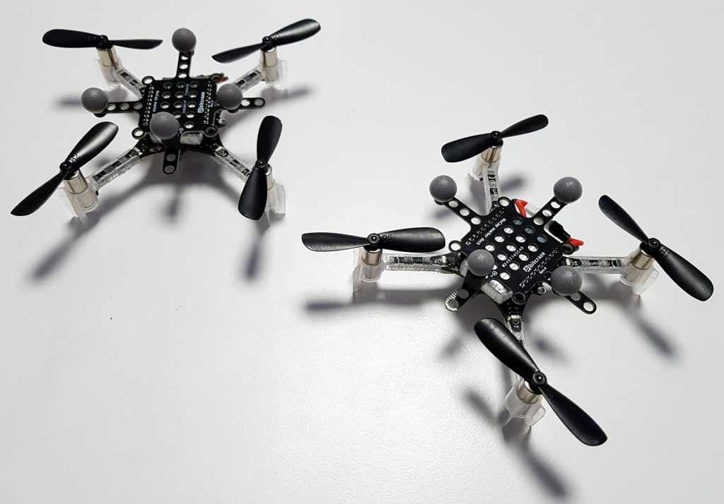
A couple of weeks ago Qualisys visited us at the Bitcraze office, they came with the Miqus motion capture system that they installed temporary in the office. This gave us the opportunity to play with their motion capture system and the Crazyflie 2.0 :-).
It was our first hands-on experience with a motion capture system. We were eager to try the algorithms that have been developed for the loco positioning system with the more precise position information offered by the motion capture. The result was above our expectations. You get a bit amazed when it is just sitting there in the air. The normally difficult in-air photo shoot became a breeze since you suddenly have plenty of time to focus and shoot.
After running a couple of simple stabilized flight demos, we endeavored to run the ICRA demo with motion capture instead of our loco positioning system. As the loco positioning deck isn’t needed it was removed and instead the measured position was sent using Crazyradio. Doing so made the demo work pretty much out of the box. The ICRA demo had 2 buttons, one for playing a pre-recorded trajectory and one for recording a path and playing it back as soon as the Crazyflie is dropped. Both modes worked seamlessly without requiring any code change. We tried the path recording and playback functionality and were pretty impressed by the precision:
We look forward of meeting and working more with Qualisys. One goal is to provide better information, documentation and tools to get started with Crazyflie in a motion capture system.
We had a booth where we demoed autonomous flight with the Crazyflie 2.0 and the Loco Positioning system, without any external computer in the loop. The core of the demo was that the Crazyflie had an onboard trajectory sequencer that enabled it to fly autonomously along a path, based on the position from the Loco Positioning system.
We had a pre programmed path that we used most of the time, since it enabled us to start the demo and the leave the Crazyflie without any further manual interference from our side (except changing battery). The other option was to manually record a path for the Crayzflie to retrace by moving it around in the flying space. When we dropped it (detecting zero gravity) the onboard sequencer and controller took over to replay the recorded path. This mode was very useful when showing the accuracy and performance of the system by recording a short sequence of one point and just leaving the Crazyflie to hover. We had mounted a deck with two buttons on the Crazyflie that we used to chose which mode to use.
The code used for the demo is available at github for anyone to play with.
Optical flow
We also showed our brand new Flow deck that we will release soon. It is a deck that is mounted underneath the Crazyflie with a downwards facing optical flow sensor. The sensor is in essence what is used in an optical mouse but with a different lens that enables it to track motion further away. The output from the deck is delta X and Y for the motion of the Crazyflie and can be used by the onboard controller to control the position. We will publish more information in this blog soon.
We had a great time talking to all you interesting, bright and awesome people. Thanks for all feedback, sharing ideas and telling us about your projects!
Last week while Kristoffer and Arnaud was in Singapore showcasing our Loco positioning system and Crazyflie at ICRA we initiated moving to a new bigger room here at The Ground. The Ground is a great business collective hosting offices for companies such as Mapilary, Monix, Castle to name a few. It is a very inspirational place to be with a great sharing climate which helps a lot for startups and early phase companies and we are happy to be part of it.
One of the nice things with the new office is that we now can have a dedicated flying area close buy and don’t have to run up and down the basement all the time. Hopefully this will help us speed up development and testing a bit, benefiting not just us, but the whole community :-).
So next time you get an email or forum post written from us you know where it is likely to have been typed.
A couple of weeks ago we played with recording and retracing trajectory directly from the Crazyflie using Loco Positioning System. The result was quite nice and resulted, a first for us, in a fully autonomous Crazyflie, no computer or controller required:
We decided to expand on this experiment for our demo at ICRA. We have modified the retracing code to accepts multiple modes, including running pre-programmed sequence. The plan for the demo is to have Crazyflies that can:
Record and retrace a manual trajectory
Record and replay in a loop a manual trajectory
Play a pre-defined trajectory in a loop
Land automatically when the battery level is low
With this we should be able to demonstrate quite well the capabilities of both the Crazyflie and the Loco Positioning system, and since we do not require a computer in the loop it simplifies a lot running the demo. Of course we keep the possibility to connect the Crazyflie with the Crazyflie client and with ROS while the crazyflie is flying.
Having a completly autonomous Crazyflie is also new to us and it brings its share of problems: how to we choose the working mode and how to we stop the flight if something happens (things tends to happen …).
To solve the former we have made a button deck that adds 2 push-button to the Crazyflie. One means “Start autonomous sequence”. The second means “Record trajectory”. If the recorded trajectory is a loop (if the end point is close to the start point) then the loop is played back as soon as the crazyflie is dropped, otherwise Crazyflie retraces the trajectory and stop.
We solved the later problem by making an autonomous emergency stop button that sends a radio watchdog signal. If the signal stops to be sent or if an emergency stop signal is sent (ie. by pressing the button), the Crazyflie will stop all motors and drop. The button is implemented using a Raspberry pi, a Crazyradio and an Arduino to interface the button:
If you are curious about code, we have created a github repos where we push all code we are making for this demo. As usual, this conference is an opportunity for us to hack new functionalities, though not everything can be done in the master branch. Later some things can be merged, others (like the retrace trajectory recorder/player that looks more like a user app.) will need much more though if we want to merge it in the Crazyflie firmware.
We have not finalized our demos yet but they will include autonomous flight with the Crazyflie and the Loco Positioning system. We also hope to show our brand new optical flow expansion deck that will enable positioning and autonomous flight when on a tight budget. We also plan to show integration with external computers running ROS or our own python library. If we are lucky there might even be a small swarm, even though the space is very limited.
We love to talk to people that are using our products or just interested in our technology, if you are at the conference please drop by and say hi and tell us what you are working on. We will arrive in Singapore on Saturday morning May 27, and if you want to hook up and say hi and have a coffee during the weekend, drop us an email.
Ever since we released the Alpha round of the Loco positioning system we’ve been talking about designing a more generic tag that could be used together with other robotics platforms for local positioning. We did a quick design of a prototype that we tested, but with the workload involved in bringing the LPS out of Early Access, finishing the Z-ranger and lots of other stuff , it’s remained on the shelf. But recently we’ve been getting more and more requests for this kind of hardware, so we thought it might be time to dust off the prototype and try to release it. One of the blockers (except workload) has been that we’re not sure how the tag should look mechanically and how to interface it electrically for it to be as useful as possible for our community. This post is for detailing the current status of the hardware/firmware and to see if we can get some feedback on what our community would like the finished product to look like.
The hardware
To make use of the firmware that’s been developed so far for the Crazyflie and the Loco positioning we aimed at making something similar to what we already have but with another form factor and slightly different requirements. As you might know the Loco positioning node can be configured as a tag, but there’s two drawbacks that we wanted to fix. First of all the Loco positioning node might be a bit big to put on smaller robots. Secondly the Loco positioning node can only measure the distances to the anchors, it doesn’t have an IMU to get attitude of the board and doesn’t have the processing power to run the same algorithms we have on the Crazyflie 2.0.
So for our Loco positioning tag prototype we decided to fix these. The prototype has the same sensors as the Crazyflie 2.0: Gyro, accelerometer, magnetometer and pressure sensor. It also has the same MCU as the Crazyflie 2.0: STM32F405. In addition to this it has the DWM1000 module for the ultra wide-band radio (used for positioning). We’ve also added the interfaces we have on the Crazyflie 2.0: SWD debugging, micro-USB for communication and power as well as a button. Looking at the pictures below you might also notice that we’ve added the Crazyflie 2.0 deck connector. So does this mean you can connect it to the Crazyflie 2.0? No, well not this prototype at least. The reason for adding it was we wanted to be able to use the same expansion decks as for the Crazyflie 2.0. So it’s possible to add the breakout deck for breadboard prototyping or the LED-ring for visual feedback.
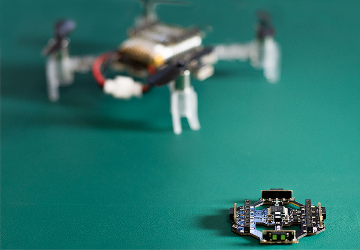
So what’s the status of the hardware? Even though it’s the first prototype it’s fully functional and will give you positioning and attitude. What’s left is defining the electrical interfaces and the form-factor of the board so it can easily be attached to what ever you might want to track. The images below shows a side-by-side comparison with the current Loco positioning deck.
Loco positioning tag (on the right) compared to Loco positioning deck (on the left) (FRONT)
Loco positioning tag (on the right) compared to Loco positioning deck (on the left) (BACK)
The firmware/software
Like I wrote above we wanted to reuse as much of the firmware and software as possible. So the firmware running on the prototype is just a scaled down version of the Crazyflie 2.0 firmware. As you might have noticed the prototype looks a lot like the Crazyflie 2.0, except that it’s not a quadcopter and doesn’t have the nRF51 radio. So by “scaled down” I mean we’ve removed the motor and radio drivers, that’s about it. So how do you communicate with it? Well you can use one of the protocol available on the deck connector: SPI, I2C or UART. But the currently implemented way is using USB. Since it’s basically a Crazyflie you can use our client and python libraries to set parameters and log data values from it.
Conclusion
The current prototype is basically a USB dongle where you get position and attitude. It could easily be connected via USB to a Raspberry Pi, Beaglebone or any other SoC based platform or a computer. You can also interface it from an Arduino using the peripherals on the deck connector. The firmware is working and using the python library (or any other of our community supported libraries) you can easily get the position and attitude of the board. But to be able to take the next step and make something our community could make the most of we would love some feedback on the prototype. What kind of electrical interfaces and form-factor would you like?
We are happy to announce that we have released new versions of the Crazyflie Firmware and the Crazyflie client, both are now in version 2017.4. The main feature of the release is support for the new Z-Ranger deck.
To support the Z-Ranger, a new flight mode has been added to both the firmware and the client: the Height-hold mode. This mode allows to fly with the Z-ranger deck at a fixed height above the floor.
There are also a number of other improvements and bug fixes in the releases, mainly related to the Loco Positioning system and autonomous flight.
On the client side, this new release is also a come-back of the windows build. It means that it is now easier to get started and fly your Crazyflie directly from Windows as you can install it as a native app. We really want to build the client for Mac OS too but have met some problems. If anyone has experience in building pyqt apps for mac OS, with your help we might be able to have a mac build for the next client version ;-).
Seeedstudio has been our main distributor and manufacturer since we started and they have also acted as our main sales channel. A couple of years ago we started to discuss setting up our own E-shop and finally last year we decided to try our own wings. We wanted to start small and treated the E-shop as an experiment, since we are newbies at e-commerce and are learning as we are going. The E-shop has been up and running for almost 10 month now without really being official, but now we have decided to go all in!
We have definitely experienced different ups and downs this last 10 months but overall it has been a positive experience. Handling the logistics and balancing stock between different warehouses have been a challenge but in return we can now communicate with and support our customers in a better way. We have been able to release hardware early to our community through our Early access program, which has been very exciting and also given us a lot of useful feedback. We have also been able to continuously improve the overall user experience by for instance creating bundles and better information architecture.
Check our store out at https://store.bitcraze.io/ and let us know what you think! We are always trying to improve and all feedback is welcome.
Remember we still have all our great local distributors, if you prefer to buy locally please check out our distributor list.