Category: Random stuff

So we did it again, forgot to post our Monday post on Monday. Are we getting sloppy or maybe it was the 16 hour travel to US that put us off track, well we need to shape up anyway! :) This Tuesday we have been visiting the USC robotics labs, more about that will come on a later post. Thanks Wolfgang for organising our visit and everybody for showing us around.

So now it is all about Maker Faire Bay Area for us. We have been putting in a lot of time to get the demos working and now we are getting really close. The autonomous control with Kinect 2 is starting to work but we must say, tuning the position PID controllers has turned out to be hard but we have some basic hovering working.

We have also been working on some LED-ring and buzzer control from the PC side. That is working really well and it is all setup using 0MQ to the cfclient. We are now able to play MIDI over the Crazyradio to the Crazyflie: MIDI -> 0MQ -> cfclient -> Crazyradio -> Crazyflie -> buzzer & LED-ring.

As soon as  we are back from Maker Faire we will make all the code available (because now it is in the quick and dirty stage)!

So once again, we would love to meet up so please come and visit ut as at our booth at the Maker Faire Bay Area!

Maker Faire Bay Area 2015

Yes, next week we are packing our bags and traveling the ~8500 Km from Malmö, Sweden to visit the Maker Faire Bay Area outside San Francisco and it is going to be great!

Malmö to Bay area We are planning some nice demos including autonomous flight with kinect2 and wireless computer controlled light effects using the LED-Ring so be sure to check us out! cf2 - kinect2 We are really looking forward to this event and we really hope you can pay us a visit if you are attending the Faire!

mf_bayarea_seeusthere


This weeks Monday post is a guest post written by Wolfgang Hoenig from University of Southern California.

What’s better than a single Crazyflie? A swarm of them! Our research group at the University of Southern California is the Automatic Coordination of Teams (ACT lab), and we research collaborative problem-solving with multiple robots. The Crazyflie is a great platform for research because of its openness and extensibility; additionally, the size allows us to test algorithms on a swarm of robots even in space-limited indoor environments.

Picture of the lab taken when 6 Crazyflie 2.0 are flying. Crazyflie are a bit small so an ellipse is drawn around them.

Picture of the lab taken when 6 Crazyflie 2.0 are flying. Crazyflie are a bit small so an ellipse is drawn around them.

After obtaining 6 Crazyflie 2.0 quadcopters and 1 Crazyflie 1.0 for our lab, we started looking into how to fly them at the same time — a basic requirement for any swarm experiments. The official Bitcraze GUI can only connect to a single Crazyflie at a time, although the underlying library comes with basic MultiFlie support. In particular, there is an URI (Uniform Resource Identifier), which has the following format if you connect using the Crazyradio: “radio://<radioIndex>/<channel>/<datarate>”. Here, radioIndex is a number starting from 0 for each attached Crazyradio, the channel is a number between 0 and 125 describing the frequency, and datarate is either 250K, 1M, or 2M. The obvious solution is to just buy one Crazyradio per Crazyflie and use separate radio indices in the URI. To avoid any form of interference, different channels need to be chosen as well. This approach has two drawbacks:

  1. The number of Crazyradios increases pretty fast, and using 7 radios for 7 Crazyflies definitely becomes unwieldy.
  1. The 2.4 GHz band becomes occupied – finding enough free frequency bands might not be easy if there are many other networks, such as Wifi or BlueTooth, around.

Bitcraze addressed the first issue a long time ago, by allowing to use a single radio for multiple Crazyflies. This approach uses PC-sided timeslicing: The radio sends a packet to the first flie and waits for an acknowledgment. Afterwards it switches the channel to the next one, and so on. The higher level requests are stored in a queue in Python, with a separate thread for each radio working on the queue. The code lived in its own branch and wasn’t updated for a while, but merging this branch with the master branch was fairly easy. There were a bunch of race conditions in the code, but most of them are hopefully fixed in my branch.

The second issue can only be solved by extending the URI itself by another unique number.

Luckily, the underlying communication protocol (Enhanced ShockBurst) by Nordic Semiconductor does have a notion of addresses. The address can be up to 5 bytes long and was simply set to 0xE7E7E7E7E7 for each Crazyflie. Making this number configurable is easy, but touches many different places in the code. It was implemented specifically for the Crazyflie 2.0, so the following discusses how it works:

  1. NRF-Firmware: This firmware runs on the NRF51, the chip which manages the power and integrates the radio. The address can be set in here, but where should we get the value from? I simply mimicked the code for setting the channel, as this was already a feature of the firmware.

In this case, the data comes from the syslink interface, which is a simple serial connection between the NRF51 and the STM32, the second microcontroller which runs the control algorithm.

  1. STM32-Firmware: This firmware has access to an EEPROM, which is able to store configuration data permanently, even during power loss. That EEPROM currently stores trim values for roll and pitch, channel, and datarate. Adding another field for the address was easy — Bitcraze even already had a version field and checksum which improves the behavior if the firmware is updated.
  1. Python Client: The Python client required three changes:
    1. Adding another configuration option field to allow a 5 byte device address. I basically copied the code for handling the channel again, plus did some additional UI work to allow a user to input hexadecimal numbers.
    2. wolfgang_config_dialog

    3. Updating the URI to “radio://<radioIndex>/<channel>/<datarate>/<address>”, where address is a 5-Byte hexadecimal number. For compatibility, the following URIs are equivalent: “radio://0/80/250K” and “radio://0/80/250K/0xE7E7E7E7E7”. This allows all existing code to work exactly like before.
    4. Adding an input field in the connect dialog to select an address. Scanning over all possible addresses isn’t feasible: There are 2^40 different possibilities!
    5. wolfgang_connection_dialog

What does this mean in practice?  That it’s now possible to control 6 Crazyflies just with 3 radios.

All these changes are already part of the official repositories; however, you’ll need the multi_radio branch to use multiple flies per radio.

And there’s even more to look forward to: An improved firmware of the Crazyradio could greatly improve the performance of the timeslicing and thus allow us to control more flies with fewer radios. Luckily, Bitcraze has already started working on it.

If you’re a researcher and use ROS, you can use our ROS driver to create your own CrazySwarm. It supports Crazyflie 1.0, Crazyflie 2.0, and the Multi-Radio and Multi-Addressing described above. It even comes with a controller to use with a motion capture system!

Have fun flieing!

Wolfgang Hoenig
PhD Student
Automatic Coordination of Teams Laboratory
University of Southern California

If you haven’t already noticed, you’re not on bitcraze.se. You’re actually on bitcraze.io (and on HTTPS). After a long week of researching, testing and holding our breaths, we’re finally on our new domain. You would think that it’s not very complicated, but as always the hole is deeper than you think… We will keep our old bitcraze.se address for a long time to come, but it will be redirecting to the io domain (this includes email). The only thing we have left to move is the forum, and it’s on it way.

A couple of weeks ago we wrote about our Monday post tradition where we post a blog-post every Monday. Sometimes we spend lots of time testing and documenting to come up with something to write, and sometimes it’s just a quick note. And that’s the way it’s been for years. But last week one of our community members (Wolfgang) offered to write a post about what he’s been up to in the USC ACT-lab. We were really excited about the offer and it spawned the idea of letting more people write guest posts. We’re really happy to see that there’s lots of interesting things happening in the community and we would really like people to get a chance to show off what they have been working on.

So if you’re working on something with your Crazyflie and would like to write a blogpost about it, drop us an email and we can see if we can fit it in!

When we were developing the Crazyflie, going from our hackish prototype to a production version, we decided to start posting a blog-post every week. Back then we always used to meet after work on Mondays to work on our project, so we named our “once-a-week” update “Monday posts”. The purpose of the posts was to show that things were happening behind the scenes, even if things looked pretty quiet. Developing something from scratch takes a lot of time and there’s not always something interesting happening, so the Monday-posts covered all sorts of things related to the project. We’ve written about the good times, the bad times and everything in between; covering tech, manufacturing, our community and trips that we’ve done.

It’s not always easy to come up with something to write about every week. Sometimes we spend lot’s of time investigating and writing about something (like RPM measurements part 1, 2 and 3) and sometimes it’s just a quick note about what’s happening. But we’ve made a point of always posting something (even on Christmas eve), and have been doing so every Monday since January 2012. So we were a bit shocked this week when we realized that it was Tuesday and we have missed posting something yesterday. But don’t worry, we’re still here and things are still happening :-)

Next month we will be attending the Bay Area Maker Faire. Last fall we visited the Maker Faire in Rome and really liked it! While there we met people from Make that invited us to the Bay Area for the next Maker Faire. It’s an awesome event with lots of technology and geeks around, so we’re really looking forward to it!

In other news we will be switching domain shortly to our bitcraze.io domain and also switching on SSL for the blog/wiki/forum. Our old bitcraze.se will still be around linking to the same site. The move is planned for this week, but like always there might be something else happening that postpones it.

Don’t forget that we still have the CCW-propeller replacement running. So if you have a Crazyflie 2.0 from the first batch and you are having issues with your propellers, then fill in the form and we will ship you a set of replacement propellers.

Last Saturday it was Arduino day 2015 and it happens that the Arduino office in Sweden is in the same building as ours. So we where invited and presented Crazyflie. It was a really fun event with a lot of interesting people passing  by and we had a lot of fun.

Arduino day 2015

There was also Helium balloon, which gave us a perfect occasion to use the blimp hack we did more than a year ago. We attached a brunch of ‘Arduino colored’ balloon to it and flew it around using the Deviation TX. It is definitly something we have to port to Crazyflie 2.o.

blimp_scaled

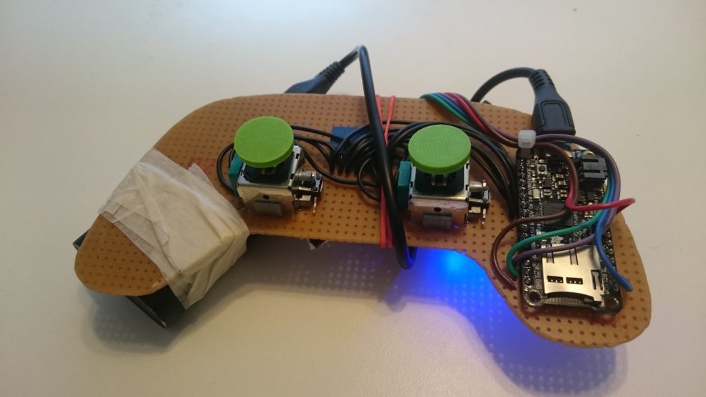
Finally as the event was hosted by Arduino, and we do not have Arduino compatibility (yet … ; ), we thought we would make something with Arduino and present it. We ended up making a Crazyflie Controller using an Arduino and using a thumb stick and ultrasonic distance sensor that was lying around the office. We attached everything to a glove to make it a ‘wearable’ controller.

arduino_glove


glove_action glove_closeup

The glove is working as follow: you place your hand over a hard surface (concrete floor or table), click the thumb-stick button to set the zero and from now-on rising the hand higher will increase the Crazyflie thrust. Then the thumb-stick can be used to steer the Crazyflie. The program is quite simple and implemented in a single loop.

Technically the most work has been put in enabling the serial port of the Crazyradio so that the Arduino can send commands to the Crazyflie using the Crazyradio directly without a computer. As there is a lot of pins available on Crazyradio and a voltage regulator capable of accepting up to ~16V, the aim has always been to be able to use it as a radio module for other system. Our first thought was PPM input, but now serial control will also be possible. We are still cleaning up the code and working on other new functionality on the Crazyradio. We plan to release a new firmware soon that will support PPM, UART and a more efficient USB protocol to communicate with many Crazyflies using one radio dongle.

We have finally managed together with Seeedstudio to improve the CCW propellers and to setup a process to acquire a free set of CCW replacement props. As continuing from this post we have discovered that many of the CCW propellers from the first batch of Crazyflie 2.0 where a bit too unbalanced. Too be a bit more technical the tolerance distribution for the CCW propellers was a bit offset, so instead of the majority being decently balanced, many where unbalanced and needed balancing. This is not really a big issue and can pretty easily be corrected by balancing them with some tape according to this guide and we still recommend them to be balanced to get the best flight performance. We however think there where to many unbalanced propellers so we offer every one that bought a Crazyflie 2.0 kit from the first batch a free set of CCW propellers including shipping from China. To acquire a free set of CCW propellers please fill in this form.

Propeller guy

During the last week there’s been lots of work, but we don’t have that much to show for it. We’ve spent a lot of time discussing what we should do during 2015. Last year there was a clear focus: develop, release and ship the Crazyflie 2.0. But up until now we haven’t really discussed what the goals for 2015 are. It’s not that we don’t have ideas, there’s always lots of ideas. It’s more about finding a common focus to work towards. It’s still ongoing, but there’s a few points that we know. We will of course continue the development (firmware, software, clients) of the Crazyflie as well as creating more expansions for the Crazyflie 2.0. For the expansion boards we’ve already talked a bit about it before, but for the firmware/software side we haven’t communicated our plan. The reason for this is simple, there’s not really been a plan for this. The main focus has been stabilization and creating clients for iPhone and Android. But now that it’s done we need to move forward with new features. If you have any feedback on this please let us know. Something that we are hoping to work on is ROS integration. (Edit: well, what do you know, this has already been started by Wolfgang Hoenig, the power of open source! Here’s a link) Once we figure out the plan we will let you now :-)

Fred, the main developer of the Crazyflie Android client, is doing a presentation about the Crazyflie at FOSDEM next weekend. Arnaud will be attending as well so if you would like to meet up, let us know!

But a few things happened during last week:

  • There’s a new release of the Android Client (thanks Fred!), so make sure to upgrade your apps!
  • We’ve added LED-ring settings to the FlighTab in the latest version on the develop branch of the client.
  • We released a bug-fix version of the python client. This new version fixes Crazyflie 2.0 configuration.
  • We added a some guideline for contributing to the client. We hope to streamline the contribution process to be more efficient at it. Tell us if you have any comments.

As for the RPM measurements and analysis we’re working on it, but it’s not ready yet… We are however making progress and it’s been very interesting, have a look at the thrust fixture we made :-).

cf2 thrust fixture

Today we were supposed to post the next part of the RPM measurements. But since we are’t finished with the analysis yet we thought that we would post some info on what we are working on. Since Christmas we have been working on and off on a new architecture for the input devices in the Crazyflie Python client. A while back we started discussing the possibility of “hooking in” different backends that could be used for input data like LeapMotion, Gamepads, sockets and so on. It’s something that we have been wanting to do for a while, but other things have always been prioritized. But during Christmas a forum request triggered the work. Users wanted to be able to change the LED-ring effects directly from the controller. We had some code for this lying around, but since the switch from PyGame to PySDL and Linux devices this wouldn’t merge easily. So we thought we might as well take this opportunity to implement what we wanted :-)

Below is a brief overview of the architecture and a description of the different parts:

Crazyflie Python client input device architecture

Each backend is implemented as a single Python file in the directory /lib/cfclient/utils/inputreaders. When the application starts up each of the files are picked up and initialized, so for anyone that wants to create their own backend it’s pretty easy. A list of successfully initialized backends is created. Once the application is started a scan of the input devices will be requested. Each of the backends will do it’s own scanning and together a big list of available devices will be created. Each of these implement a specific API for opening, closing, scanning and reading the device by using their respective backends. The higher layer (Input) now has a list of available devices that it can open and read. But to make sense of the data read from the devices a mapping needs to be created to set which axes/buttons effect what parameters. There’s a number of parameters that can be changed, the main ones being roll/pitch/yaw/thrurst for controlling the Crazyflie. In order to make the mappings as flexible as possible each mapping has a scale and offset. It’s also possible to split axis, so two axis on the device can effect the same parameters (like having yaw on bumper buttons). Normally (for PySDL2 and linuxjsdev) all axis are between -1 and 1 and buttons are either 0 or 1. But using the mappings it’s possible to have other values, like for the LeapMotion. When the LeapMotion is read it return the roll/pitch/yaw/height as read from the device. Using the mappings offset and scaling these values are transformed into usable values for roll/pitch/yaw/thrust. Here’s a step by step walkthough of how a device is read:

  • Input: Each 10 ms the open device is read
  • InputDevice: Asks the backend for reading the device
  • Backend: When read two arrays are updated, one for the buttons and one for the axes. If the device is event based all the events are consumed before updating
  • InputDevice: Takes the raw values from the backend, iterates though them and updates a list of highlevel parameters accordingly. This returns a dictionary with keys like roll/pitch/yaw/thrust
  • Input: Pre-processes the values of the parameters, like only calling callbacks when there’s a state shift (button 0->1 or 1->0), slew-rate limiting the thrust, dead-band and trimming
  • Input: Calls special callbacks (such as alternative functions and emergency stop)
  • Input: Calls callbacks registered for control data (roll/pitch/yaw/thrust). For this there are two registered callbacks, the UI and the Crazyflie object (crazyflie.commander.send_setpoint(…))

So how does this help the original problem of setting parameters from buttons? In this change we have also included two new buttons, alt1 and alt2. These can be mapped just like any other buttons in the configuration dialog. When these buttons are toggled (0->1 and 1->0) all the registered callbacks are called. The idea is not mapping them graphically to specific parameters, it’s for enabling users to easily (with one line of code) register for these and be able to act on them. For instance setting the LED-ring headlights on/off or changing the effect of the LED-ring.

When we are poking around in the code we are also looking at fixing some other issues, like how to handle when Bluetooth controllers go out of range (see this topic in the forum). We are hoping that everything will be finished and merged when the next release of the client. Also a big thanks to everyone that’s contributed code for the input reading, it’s made things a lot easier!

Today we also released new firmware for the Crazyflie 1.0 and a new Crazyflie Python Client. We have now fixed the client compatibility issues between the Crazyflie 1.0 and 2.0. We are also happy to report that next week the LED-ring and the Crazyradio PA should be back in stock.


The Crazyflie 2.0 supports two types of radio protocols out of the box: ESB (Enhanced ShockBurst) for Crazyradio/Crazyradio PA USB dongle compatibility and  Bluetooth LE for mobile devices. All Crazyflie 2.0’s are shipped with a radio bootloader, able to update virtually all the different parts of the firmware running in Crazyflie 2.0. We thought we would do a post to explain a bit further how it all fits together. Even though the Crazyflie 2.0 supports Bluetooth LE, the preferred way is to use the Crazyradio/Crazyradio PA when doing development. Flying via Bluetooth is very practical since there’s no additional hardware needed except for a mobile device, but the Crazyradio/Crazyradio PA has minimal latency, more bandwidth and works easily with computer. This makes it ideal for development and other advanced usage.

(On a side note, some of our products are currently out of stock (like the Crazyradio PA and LED-ring). We have started the next batches, so they should arrive soon. Until then have a look at our distributor page to find our products.)

Crazyflie 2.0 architecture

For the radio of Crazyflie 2.0 we choose the nRF51822. The great thing with this chip is that it integrates a radio compatible with our existing Crazyradio USB dongle as well as with Bluetooth Low Energy. The nRF51 also integrates an ARM Cortex-M0 MCU enabling radio protocols to be implemented directly in the chip. However this MCU is not powerful enough to be used by itself in our quadcopter development platform, so we put a powerful STM32F4 Cortex-M4 168MHz on the side to do the heavy work.

The nRF51 mainly handles radio and power management and the STM32F4 handles all the rest: flight control, expansion port, log, param, etc. As far as the radio is concerned the nRF51 act as a bridge: CRTP packets are received by the nRF51 and sent unmodified to the STM32F4 and the STM32F4 sends raw CRTP packets to the nRF51 that transmit it by the radio. This means that the STM32 firmware is unaware of the physical communication protocol, it can be Bluetooth, Shockburst or something else, it makes no difference it is still CRTP packets. CRTP is the protocol used to control Crazyflie, it encapsulates all commands and messages exchanged between the client and the Crazyflie.

Enhanced Shockburst (ESB)

Enhanced Shockburst is a radio physical protocol implemented in some Nordic Semiconductor 2.4GHz radio chips. In the nRF24 chip, used by Crazyradio (PA) and the original Crazyflie, this protocol is implemented in hardware and we have little control over it. The nRF51 used in Crazyflie 2.0 offers more control on the radio physical packet and ESB since it’s implemented in software instead.

ESB handles ack and retries: The Crazyradio sends a packet on a given channel and waits for an ack. If a Crazyflie receives the packet without error it sends an ack packet. If an ack is received, the Crazyradio can send the next packet. If no ack is received Crazyradio will automatically retry by sending the same packet again. The current implementation will retry to send a packet forever, so all packet are guaranteed to be transmitted as long as a Crazyflie is in range. Packets are sent back by the Crazyflie by adding a data payload to the ack packet. Close to 80 different channel can be used and every packet is sent with an access address, so more than one Crazyflie could share the same channel.

Enhanced Shockburst using the Crazyradio (PA) offers the lowest latency that can be expected. The minimum latency to send a packet is estimated to about 2ms (1ms minimum for USB and 1ms measured latency for the radio at 2Mbps without any retries). With the Crazyflie 2.0 and the Crazyradio PA it also offers the maximum range with 20dBm power output.

For the original Crazyflie there is an implementation of the E-sky RC transmitter protocol. This permits controlling the Crazyflie directly from an RC transmitter. It is technically possible to implement this protocol in the Crazyflie 2.0 nRF51, but it hasn’t been done yet.

Bluetooth Low Energy

In the Crazyflie 2.0 Bluetooth low energy is implemented as a CRTP bridge: CRTP packet are written and read using Bluetooth. This simplifies greatly the implementation, but does not make full use of the Bluetooth LE functionality. It is planned to add more Bluetooth capabilities for things like communicating the battery status and being able to switch ON or OFF the Crazyflie with a mobile devices.

On the nRF51 side the Bluetooth functionality is implemented using the Nordic Semiconductor S110 Bluetooth stack. This stack runs independently of the firmware. Nordic calls this a softdevice and it’s a fitting description of how it works. It almost looks like a hardware device from the firmware point of view as it is not linked into the main firmware.

However we do not currently have the right to distribute the supporting files for the stack, so unfortunately you will have to download them yourself if you want to compile your own nRF51 Bluetooth firmware. To do so you must own a Nordic Semiconductor development kit. Even though some of the kits are pretty cheap, we do not like this situation at all so we are working on solving it. However we made sure that it is possible to compile the nmRF51 firmware without Bluetooth, to avoid the added dependencies. This means that you can still build your own nRF51 firmware to work with a Crazyradio/Crazyradio PA.

Bootloader/firmware upgrade

The Crazyflie 2.0, like the original Crazyflie, is upgradable wirelessly with radio. The radio bootloader has been enhanced to work both with ESB and Bluetooth LE. Both nRF51 and STM32F4 can be upgraded and it is even possible to upgrade the nRF51 Bluetooth stack and bootloader.

Currently the bootloader is working with Crazyradio on ESB. Bluetooth implementation for iPhone and Android is still work in progress. The STM32F4 can also be upgraded via USB and so, for people that does not have a Crazyradio, the first Crazyflie 2.0 firmware upgrade has been released for USB DFU as well as the classical radio bootloader update package.