Category: Research

Grasping objects is a hard task that usually implies a dedicated mechanism (e.g arm, gripper) to the robot. Instead of adding extra components, have you thought about embedding the grasping capability to the robot itself? Have you also thought about whether we could do it flying?

In the GRASP Laboratory at the University of Pennsylvania, we are concerned about controlling robots to perform useful tasks. In this work, we present the Flying Gripper! It is a novel flying modular platform capable of grasping and transporting objects with the help of multiple quadrotors (crazyflies) working together. This research project is coordinated by Professor Mark Yim and Professor Vijay Kumar, and led by Bruno Gabrich (PhD candidate) and David Saldaña (Postdoctoral researcher).


Inspiration in Nature

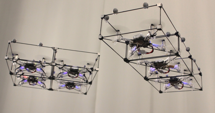
In nature, cooperative work allows small insects to manipulate and transport objects often heavier than the individuals. Unlike the collaboration in the ground, collaboration in air is more complex especially considering flight stability. With this inspiration, we developed a platform composed of four cooperative identical modules where each is based on a quadrotor (crazyflies) within a cuboid frame with a docking mechanism. Pair of modules are able to fly independently and physically connect by matching their vertical edges forming a hinge. Four one degree of freedom (DOF) connections results in a one DOF four-bar linkage that can be used to grasp external objects. With this platform we are able to change the shape of the flying vehicle during flight and use its own body to constrain and grasp an object.

Flying Gripper Design and Motion

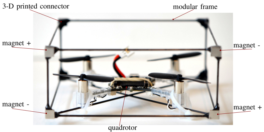
In the proposed modular platform, we use the Crazyflie 2.0. Its battery life lasts around seven minutes, though in our case battery life time is reduced due to the extra weight. The motor mounting was modified from the standard design, we tilted the rotors 15 degrees. This was necessary as more yaw authority was required to enable grasping as a four-bar. However, adding this tilt reduces the lifting thrust by 3%. Axially aligned cylindrical Neodymium Iron Boron (Nd-FeB) magnets, with 1/8″ of diameter and 1/4″ of thickness are mounted on each corner enabling edge-to-edge connections. The cylindrical magnets have mass of 0.377g and are able to generate a force of 0.4 kg in a tangential connection between two of the same magnets. This forms a strong bond when two modules connect in flight. Note that the connections are not rigid – each forms a one DOF hinge.

The four attached modules results in a one DOF four bar linkage in addition to the combined position and attitude of the conglomerate. The four-bar internal angles are controlled by controlling the yaw attitude of each module. For example, two modules rotate clockwise and other two modules rotate counter-clockwise in a coordinated manner.


Grasping Objects

Collaborative manipulation in air is an alternative to reduce the complexity of adding manipulator arms to flying vehicles. In the following video we are able to see the Flying Gripper changing its shape in midair to accomplish the complex task of grasping a wished coffee cup. Would you like some coffee delivery?


This work was developed by:

Bruno Gabrich, David Saldaña, Vijay Kumar and Mark Yim

Additional resources at:

http://kumarrobotics.org/

http://www.modlabupenn.org/

This week’s Monday post is a guest post written by members of the Computer Science and Artificial Intelligence Lab at MIT.

One of the focuses of the Distributed Robotics Lab, which is run by Daniela Rus and is part of the Computer Science and Artificial Intelligence Lab at MIT, is to study the coordination of multiple robots. Our lab has tested a diverse array of robots, from jumping cubes to Kuka youBots to quadcopters. In one of our recent projects, presented at ICRA 2017, Multi-robot Path Planning for a Swarm of Robots that Can Both Fly and Drive, we tested collision-free path planning for flying-and-driving robots in a small town.

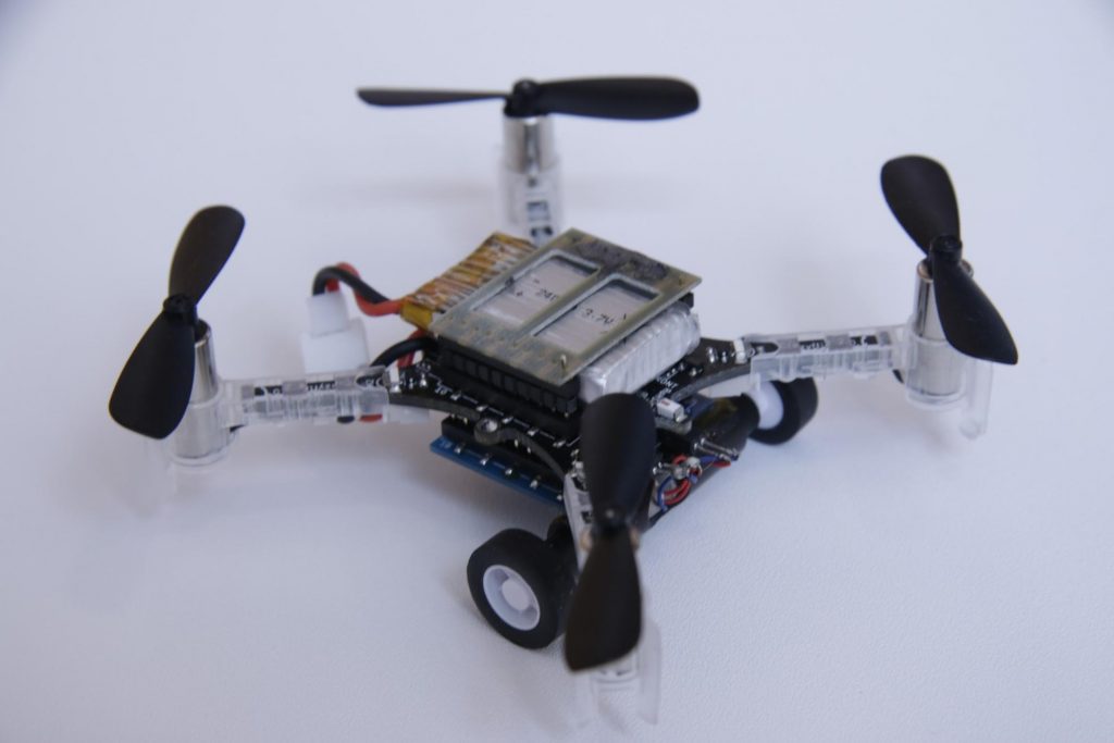
Robots that can both fly and drive – in particular wheeled drones – are actually somewhat of a rarity in robotics research. Although there are several interesting examples in the literature, most of them involve creative ways of repurposing the wings or propellers of a flying robot to get it to move on the ground. Since we wanted to test multi-robot algorithms, we needed a robot that would be robust, safe, and easy to control – not necessarily advanced or clever. We decided to put an independent driving mechanism on the bottom of a quadcopter, and it turns out that the Crazyflie 2.0 was the perfect platform for us. The Crazyflie is easily obtainable, safe, and (we can certify ourselves) very robust. Moreover, since it is open-source and fully programmable, we were able to easily modify the Crazyflie to fit our needs. Our final design with the wheel deck is shown below.

A photo of the Crazyflie 2.0 with the wheel deck.

A model of the Crazyflie 2.0 with the wheel deck from the bottom

The wheel deck consists of a PCB with a motor driver; two small motors mounted in a carbon fiber tube epoxied onto the PCB; and a passive ball caster in the back. We were able to interface our PCB with the pins on the Crazyflie so that we could use the Crazyflie to control the motors (the code is available at https://github.com/braraki/crazyflie-firmware). We added new parameters to the Crazyflie to control wheel speed, which, in retrospect, was not a good decision, since we found that it was difficult to update the parameters at a high enough rate to control the wheels well. We should have used the Crazyflie RealTime Protocol (CRTP) to send custom data packages to the Crazyflie, but that will have to be a project for another day.
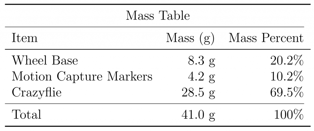
The table below shows the mass balance of our miniature ‘flying car.’ The wheels added 8.3g and the motion capture markers (we used a Vicon system to track the quads) added 4.2g. So overall the Crazyflie was able to carry 12.5g, or ~44% of its body weight, and still fly pretty well.


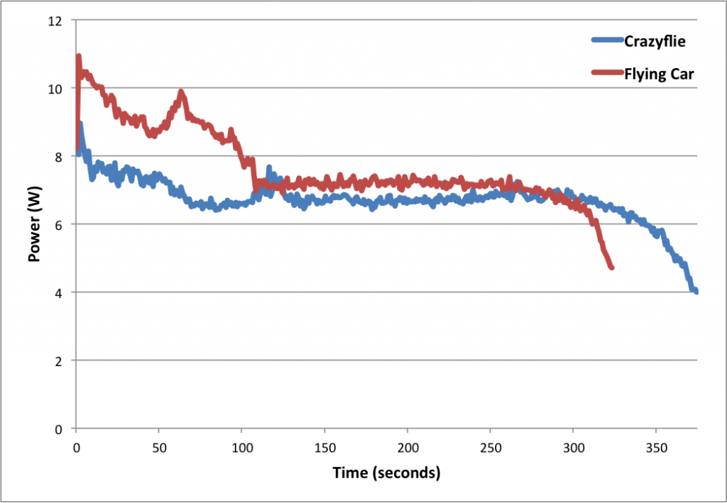
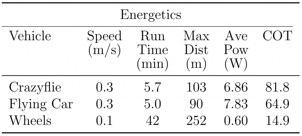
Next we measured the power consumption of the Crazyflie and the ‘Flying Car.’ As you can see in the graph below, the additional mass of the wheels reduced total flight time from 5.7 minutes to 5.0 minutes, a 42-second or 12.3% reduction.

Power consumption of the Crazyflie vs. the ‘Flying Car’


The table below shows more comparisons between flying without wheels, flying with wheels, and driving. The main takeaways are that driving is much more efficient than flying (in the case of quadcopter flight) and that adding wheels to the Crazyflie does not actually reduce flying performance very much (and in fact increases efficiency when measured using the ‘cost of transport’ metric, which factors in mass). These facts were very important for our planning algorithms, since the tradeoff between energy and speed is the main factor in deciding when to fly (fast but energy-inefficient) versus drive (slow but energy-efficient).

Controlling 8 Crazyflies at once was a challenge. The great work by the USC ACT Lab (J. A. Preiss, W. Hönig, G. S. Sukhatme, and N. Ayanian. “Crazyswarm: A Large Nano-Quadcopter Swarm,” ICRA 2017. https://github.com/USC-ACTLab/crazyswarm) has made our minor effort in this field obsolete, but I will describe our work briefly. We used the crazyflie_ros package, maintained by Wolfgang Hönig from the USC ACT Lab, to interface with the Crazyflies. Unfortunately, we found that a single Crazyradio could communicate with only 2 Crazyflies at a time using our methods, so we had to use 4 Crazyradios, and we had to make a ROS node that switched between the 4 radios rapidly to send commands. It was not ideal at all – moreover, we had to design 8 unique Vicon marker configurations, which was a challenge given the small size of the Crazyflies. In the end, we got our system to work, but the new Crazyswarm framework from the ACT Lab should enable much more impressive demos in the future (as has already been done in their ICRA paper and by the Robust Adaptive Systems Lab at Carnegie Mellon, which they described in their blog post here).

We used two controllers, an air and a ground controller. The ground controller was a simple pure pursuit controller that followed waypoints on ground paths. The differentially steered driving mechanism made ground control blissfully simple. The main challenge we faced was maximizing the rate at which we could send commands to the wheels via the parameter framework. For aerial control, we used simple PID controllers to make the quads follow waypoints. Although the wheel deck shifted the center of mass of the Crazyflie, giving it a tendency to slowly spin in midair, overall the system worked well given its simplicity.

Once we had the design and control of the flying cars figured out, we were able to test our path planning algorithms on them. You can see in the video below that our vehicles were able to faithfully follow the simulation and that they transitioned from flying to driving when necessary.

Link to video

Our work had two goals. One was to show that multi-robot path planning algorithms can be adapted to work for vehicles that can both fly and drive to minimize energy consumption and time. The second goal was to showcase the utility of flying-and-driving vehicles. We were able to achieve these goals in our paper thanks in part to the ease of use and versatility of the Crazyflie 2.0.

This week’s Monday post is a guest post written by members of the Robust Adaptive Systems Lab at Carnegie Mellon University.

As researchers in the Robust Adaptive Systems Lab (Director: Prof. Nathan Michael) at Carnegie Mellon University http://rasl.ri.cmu.edu, we’re interested in developing algorithms for control, planning, and coordination to enable robots to adapt to their environments, and we use the Crazyflie platforms to help us test our theory on real world systems.

We employ Crazyflie quadrotors to evaluate several research objectives in our lab. One research thrust looks at enabling a platform to learn new controllers as it flies, allowing the quadrotor to automatically switch between controllers to handle specific flight conditions. Another objective looks at adapting flight plans for multiple robots in real time, based on what a user tells the robots to do. We use the Crazyflie platform to evaluate our algorithms because the hardware is robust and the user community has helped make firmware available on which we can base our own systems (J. A. Preiss, W. Hönig, G. S. Sukhatme, and N. Ayanian. “Crazyswarm: A Large Nano-Quadcopter Swarm,” ICRA 2017. https://github.com/USC-ACTLab/crazyswarm). At the same time, the power and memory constraints of the Crazyflie force us to pursue efficient algorithms that can handle real world considerations such as limited battery life and computing restrictions.

We’re bringing these research ideas together to make an adaptive multi-robot system that a person can direct online and operate over long periods of time–longer than the lifespan of a single battery. In this blog post, we wanted to share a bit of information about some of the research we’re working on that uses the Crazyflie platforms. We look at single-robot controllers, multi-robot planning systems, and hardware designs to move us towards a persistent, adaptive swarm of Crazyflies.

Control Approaches

We have looked at implementing advanced control strategies onboard the Crazyflie for improved safety and flight performance. This includes an extremely efficient formulation of explicit Model Predictive Control (MPC) developed specifically for systems like the Crazyflie that have severe computational constraints due to size, weight, and power limitations. MPC optimizes the control commands based on current and predicted motion, allowing us to enforce speed limits and avoid motor saturation. The controller is run in a separate task on the STM32F405 MCU, allowing it to maintain a 100 Hz position control rate without blocking other components, such as the state estimator and attitude controller.

In the image above, the vehicle uses MPC control to rapidly and accurately move between two destinations. [V. R. Desaraju and N. Michael, “Fast Nonlinear Model Predictive Control via Partial Enumeration,” ICRA 2016.]

Multi-robot Systems

Another element of our research emphasizes adapting plans for multi-robot systems online, in order to translate a human operator’s intent into dynamically feasible and safe motion plans. We are using a swarm of Crazyflies for hardware validation of the online motion planning algorithms.

Our experimental testbed consists of a Vicon motion capture system that provides the state information (position and orientation) of the robots. The position coordinates and the heading angle are broadcast to the individual Crazyflies using the radios at a rate of 100 Hz. A centralized planner, running on a separate thread, parses user instructions into dynamically feasible and safe motion plans for each individual robot. The user instructions consists of high level information such as robot ids, behavior type (go to a target destination, rotate in a circle), and formation shapes (line, polygon, 3D). Once the feasible and safe motion plans are computed, the desired position setpoints are broadcasted to the Crazyflies at a rate of 30 Hz.

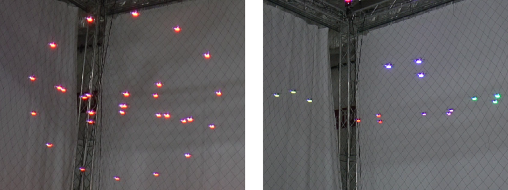
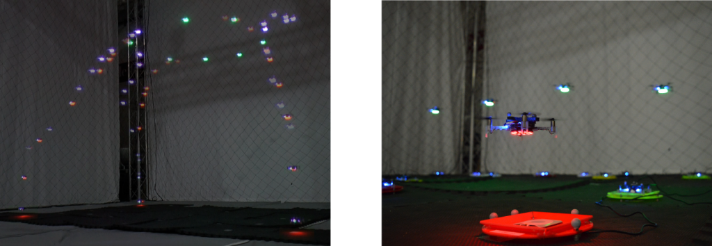
These images show a formation of 30 Crazyflies in a 3D shape and five groups of three Crazyflies, flying around a motion capture arena in response to a user’s direction. The multi-robot planner computes these flight plans online in response to the user’s commands, without any prior planning. [Ellen A. Cappo, Arjav Desai and Nathan Michael. “Robust Coordinated Aerial Deployments for Theatrical Applications Given Online User Interaction via Behavior Composition,” DARS 2016.]

Hardware Considerations 

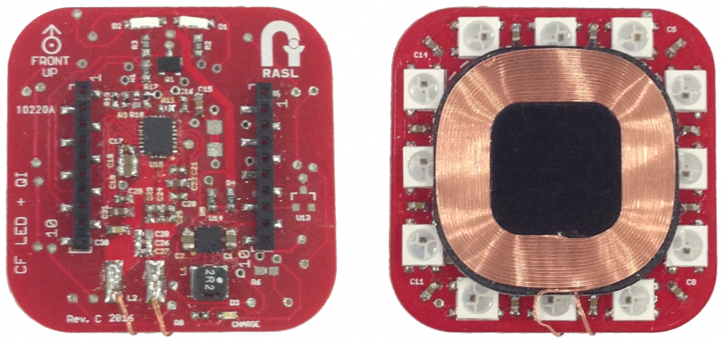
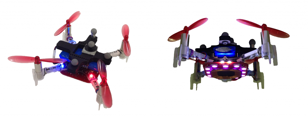
As we move towards operating for long periods of time, we needed to incorporate the Qi inductive charger to enable the robots to recharge. We also want to retain the LEDs, to keep an aesthetic visual element and act as status indicators. There were two concerns with using both the standard LED and Qi decks: they both mount to the bottom of the Crazyflie, and both decks add weight. We created a combined deck based on the schematics from the Bitcraze wiki, and the final deck is shown below and weighs in at 6-7g.

Even with the combined Qi + LED deck, we observe shorter flight times and motor saturation with the Crazyflie flights, so we increased the battery capacity and flying with different motor and propeller combinations. Pictured below is a Crazyflie with 7×20 motors using 55mm propellers and a 500mAh battery, and carrying a foam mount for the motion capture markers. No frame modifications are required as the motors fit in the mounts and the battery is chosen to fit within the header pins. These changes resulted in an increase in flight time, greater control margin and aggressiveness, and larger payload capacity.

Toward Persistent Operation

The capabilities we mentioned above allow us to work towards long duration operation. We are currently integrating our adaptive control, online planning, and efficient hardware design to enable persistent operation of a swarm of Crazyflies. To achieve this goal, we are developing scheduling algorithms that update flight plans based on battery capacities across a Crazyflie fleet. The flight planner calculates trajectories that allow robots with full batteries to exchange places with robots with expired batteries, landing Crazyflies that need to recharge onto charging stations. In the first image below, 10 robots rotate in a circle formation. The time-lapsed image shows three Crazyflies with full batteries (with blue LEDs) exchange places with three Crazyflies with depleted batteries (with red LEDs). The second photo shows a close-up of our Crazyflie charging station.

In closing, we show a few video clips of Crazyflie flight illustrating the research we discuss here. We show a group of fifteen Crazyflies following online-issued commands to split and merge between formations; a formation of 30 Crazyflies; and an example of our exchange planner, substituting robots into a multi-robot formation and returning robots to ground station locations.

Contributors: Ellen Cappo, Arjav Desai, Matt Collins, Derek Mitchell, and Vishnu Desaraju, students and researchers at the Robust Adaptive Systems Lab (Director: Prof. Nathan Michael), Carnegie Mellon University.

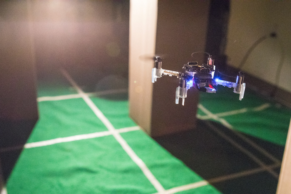
This week we got an email from David Gómez, a research scientist at Multi-Agent Autonomous Systems Lab, Intel Labs. He and his team have done some cool work on trajectory planning in cluttered environments that we think needs to be shared. For their research they used the Crazyflie 2.0 which we think is even cooler :-). Watch the video to see how the Crazyflie 2.0 find its way though narrow corridors and obstacle dense environments.


If you are interested in the full paper, “A Hybrid Method for Online Trajectory Planning of Mobile Robots in Cluttered Environments”, you can find it under Crazyflie 2.0 publications in the research section.

What’s better than a single Crazyflie? A swarm of them! Over a year ago our research group at the University of Southern California posted a blog post with the title “Towards CrazySwarms“, explaining how to fly six Crazyflies at the same time. Since then, we’ve expanded our fleet to 49 Crazyflies. It turns out that flying 49 requires a completely different approach. We will outline the additional challenges, and of course show a fun video!

Why is flying many Crazyflies hard? It comes down to two different categories:

  1. Communication Limitations: The standard Crazyflie software does not support controlling more than one crazyflie per radio. Putting 49 radios on a PC is possible, but would cause very high latencies because the Universal Serial Bus (USB) operates, as the name suggests, serially in 1 ms intervals. Earlier, we showed that we can share a radio for two Crazyflies by using different addresses, but 25 radios are still too much to be handled on one PC reasonably. We can overcome this issue by reducing the amount of data to be transferred. However, this forces us to increase the autonomy of the Crazyflie. Instead of sending attitude control input for each Crazyflie at a high rate, we move the controller on-board and send high-level trajectory descriptions and external position information at a low-rate. In particular, we need to:
    1. Move the position controller on-board, and
    2. Be able to handle packet losses more gracefully.

    i) is relatively easy, apart from the testing and tuning. For ii) we use an Extended Kalman Filter to estimate the state on-board. This state, consisting of the position, angle, and the translational velocities, is estimated by combining the on-board sensors (gyroscope, accelerometer) with external position information. Even if we are not able to send the external position for a while due to packet drops, the on-board sensors will keep the estimated state correct for a while.
    Finally, we implemented broadcasts (rather than 1-to-1 communication between PC and each Crazyflie) and used a number of compression tricks in order to limit the required bandwidth further. We are able to broadcast the pose (position and rotation) for all 49 Crazyflies using just three Crazyradios 100 times per second. Each Crazyflie can handle several packet drops in a row before the state estimate becomes too unreliable to fly.

  2. External Position Feedback: The on-board sensors of the Crazyflie are not sufficient to determine its position, so we need some external position feedback. In academia, optical motion capture systems are frequently used. They consist of a number of specialized, synchronized, high-speed infrared cameras. Each object to track is equipped with at least three retroreflective spheres (so-called markers), which reflect infrared light sent out by the IR light sources next to the cameras. If we know the pose of all cameras, we can use triangulation to determine the 3D positions of all retroreflective markers.Traditionally, motion capture systems require that each object has a unique arrangement of markers; this allows to determine each object’s position from a single frame of marker data by searching for its unique pattern. Unfortunately,  the Crazyflie is too small to have 49 unique marker arrangements that can be reliably distinguished. To solve that issue, we put the Crazyflies at known positions initially and use their marker arrangement to track their position and pose over time, at 100 Hz. This allows us to use the same marker arrangement for each Crazyflie.
 

Putting that together (combined with an improved controller), allows us to create nice formations:

So what is next? Eventually, we will integrate our changes into the various projects (including the firmwares and the ROS driver), allowing everyone to work on and with CrazySwarms.

Have fun flieing!

Wolfgang Hönig
PhD Student
Automatic Coordination of Teams Laboratory
University of Southern California
James Preiss
PhD Student
Robotics Embedded Systems Laboratory
University of Southern California