Once the state estimator have outputed the current (estimated) situation of the crazyflie in position velocity and attitude, it is time for the controllers to keep it that way or to move the crazyflie into a new position based on a setpoint. This is an important part of the stabilization system in the crazyflie.
- Overview of control
- Cascaded PID controller
- Mellinger Controller
- INDI Controller
- Brescianini Controller
- Lee Controller
Overview of control
There are four levels to control in the Crazyflie:
- Attitude rate
- Attitude absolute
- Velocity
- Position
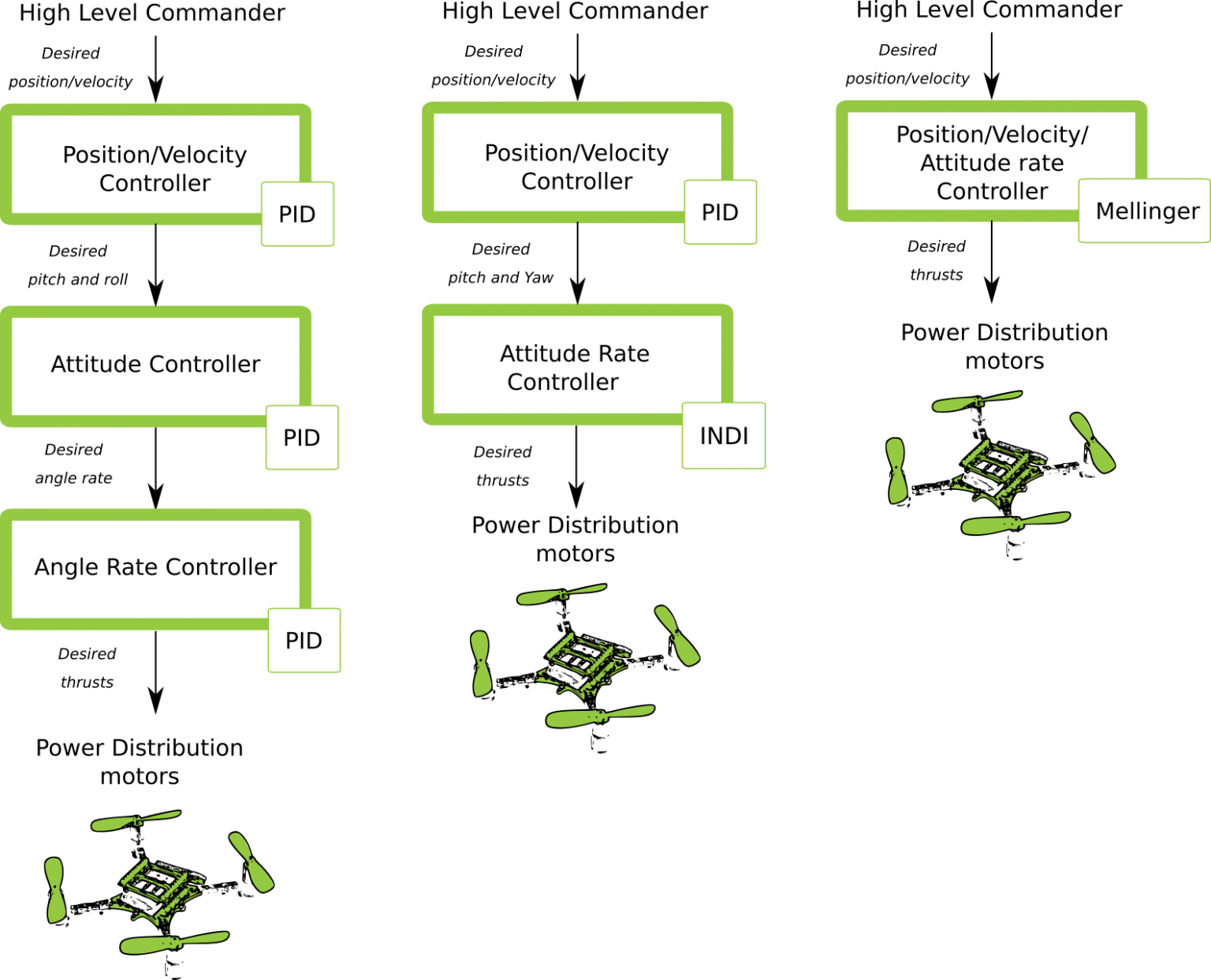
Here is an overview of the types of controllers there are per level:

We will now explain per controller how exactly they are being implemented in the crazyflie-firmware.
Cascaded PID controller
By default, the Crazyflie firmware utilizes proportional integral derivative (PID) control to manage the drone’s state. The firmware employs distinct PID controllers for each control level: position, velocity, attitude, and attitude rate. The output of each controller feeds into the input of the next, lower level controller, forming a cascaded PID structure. Depending on the control mode, different setpoints can be fed into the system, influencing which PID controllers are activated. For instance, when using attitude rate setpoints, only the attitude rate PID controller is active; for attitude setpoints, both the attitude and attitude rate PID controllers are used; and so on for velocity and position setpoints. Ultimately, regardless of the control mode, the angle rate controller translates the desired angle rates into PWM commands for the motors.
To enhance control stability and prevent issues during significant setpoint changes, we have implemented a workaround to avoid derivative kick—a sudden spike in control output caused by changes in the setpoint. This workaround calculates the derivative term using the rate of change of the measured process variable rather than the rate of change of the error. By preventing derivative kick, particularly during large setpoint changes, this approach ensures smoother and more reliable control.
Here is a block schematics of how the PID controllers are implemented.

Here are the different loops of the cascaded PID explained in more detail.
Attitude Rate PID controller
The attitude rate PID controller is the one that directly controls the attitude rate. It receives almost directly the gyroscope rates (through a bit of filtering first) takes the error between the desired attitude rate as input. This output the commands that is send directly to the power distribution power_distribution_quadrotor.c. The control loop runs at 500 Hz.
Check the implementation details in attitude_pid_controller.c in attitudeControllerCorrectRatePID().
Attitude PID controller
The absolute attitude PID controller is the outer-loop of the attitude controller. This takes in the estimated attitude of the state estimator, and takes the error of the desired attitude set-point to control the attitude of the Crazyflie. The output is desired attitude rate which is send to the attitude rate controller. The control loop runs at 500 Hz.
Check the implementation details in attitude_pid_controller.c in attitudeControllerCorrectAttitudePID().
Position and Velocity Controller
The most outer-loop of the cascaded PID controller is the position and velocity controller. It receives position or velocity input from a commander which are handled, since it is possible to set in the variable setpoint_t which stabilization mode to use stab_mode_t (either position: modeAbs or modeVelocity). These can be found in stabilizer_types.h. The control loop runs at 100 Hz.
Check the implementation details in position_controller_pid.c in positionController() and velocityController().
Mellinger Controller
Conceptually the Mellinger controller is similar to the cascaded PID controller, i.e. there is an attitude controller (running at 250 Hz) and a position controller (running at 100 Hz). The main difference to the cascaded PID controller is how errors are defined and how the position error is translated into desired attitude setpoints. Like the cascaded PID, this is a reactive geometric controller that uses the mathematical property of differential flatness. Details are given in the following scientific publication:
Daniel Mellinger, and Vijay Kumar
Minimum snap trajectory generation and control for quadrotors
IEEE International Conference on Robotics and Automation (ICRA), 2011
https://doi.org/10.1109/ICRA.2011.5980409
The implementation follows the paper, also for the names of the variables. The main difference is the addition of I-gains and a D-term for the angular velocity.
INDI Controller
This control algorithm is the Incremental Nonlinear Dynamic Inversion (INDI) controller. Details are given in the following scientific publication:
Ewoud J. J. Smeur, Qiping Chu, and Guido C. H. E. de Croon
Adaptive Incremental Nonlinear Dynamic Inversion for Attitude Control of Micro Air Vehicles
JCGD 2015
https://doi.org/10.2514/1.G001490
Brescianini Controller
Details of this controller are in the following scientific publication:
Dario Brescianini, Markus Hehn, and Raffaello D'Andrea
Nonlinear quadrocopter attitude control
Technical Report ETHZ, 2013
https://doi.org/10.3929/ethz-a-009970340
Lee Controller
Conceptually the Lee controller is similar to the cascaded PID controller, i.e. there is an attitude controller (running at 250 Hz) and a position controller (running at 100 Hz). The main difference to the cascaded PID controller is how errors are defined and how the position error is translated into desired attitude setpoints. Like the cascaded PID, this is a reactive geometric controller that uses the mathematical property of differential flatness. Compared to the Mellinger controller, a different angular velocity error and higher-order terms in the attitude controller are used. Details including a stability proof are given in the following scientific publication:
Taeyoung Lee, Melvin Leok, and N. Harris McClamroch
Geometric Tracking Control of a Quadrotor UAV on SE(3)
CDC 2010
https://doi.org/10.1109/CDC.2010.5717652
The implementation follows the paper, also for the names of the variables. The main difference is the addition of I-gains, which are not needed for the theoretical proof, but helpful on the practical system.