Introduction
The loco positioning system can be configured in two modes; Two Way Ranging (TWR) mode and in Time Difference of Arrival (TDoA) mode. The set up procedure is more straightforward in TWR mode and we recommend to use this mode also if you intend to use the system in TDoA mode as the switch to TDoA is easy to do after the setup. This guide describes the procedure using the TWR mode and at the end how to switch to TDoA mode.
In order to illustrate anchor placements we have documented two reference systems, one with 6 anchors and one with 8. The 6 anchor setup is mainly intended for TWR use while we recommend 8 anchors for the TDoA mode.
Update the Crazyflie to the latest loco positioning firmware
To be able to use the Loco positioning system you need to update the Crazyflie to the latest firmware. For more information on how to update the firmware, see the update firmware in the Crazyflie section in our Getting started with the Crazyflie 2.0 or Crazyflie 2.1(+).
You will also need the latest version of the Crazyflie client.
For mounting the Loco Positioning deck check out the Getting started with expansion decks tutorial.
Preparing the anchors
Before setting up the system you need to update the firmware and configure the the nodes.
Download the Loco Positioning configuration tool
Download and run the Loco Positioning configuration tool .exe installer to install the Loco Positioning tool.
Clone the Loco Positioning configuration tool GIT repo and follow the readme instruction to run the tool.
Download the Loco Positioning node firmware
For the latest Loco Positioning node firmware go here and download the “lps-node-firmware.dfu” file.
Update the nodes
- To update the node start by opening up the Loco Positioning configuration tool. Keep the DFU button on the node pressed while connecting to your computer via USB. This will start the node in DFU mode.
- If you are using Windows, the node will not be recognized the first time. You need to follow the instruction to install its USB driver using Zadig. In DFU mode, the node will be displayed as “STM32 BOOTLOADER” in Zadig.
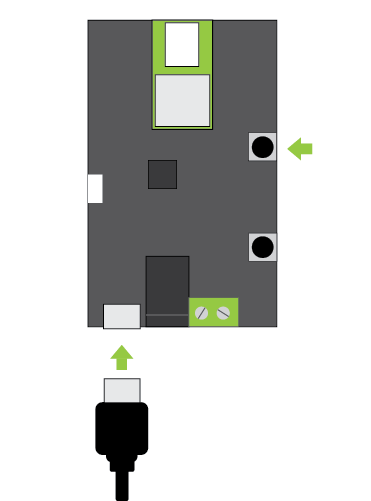
- Click browse and choose the Loco Positioning node firmware
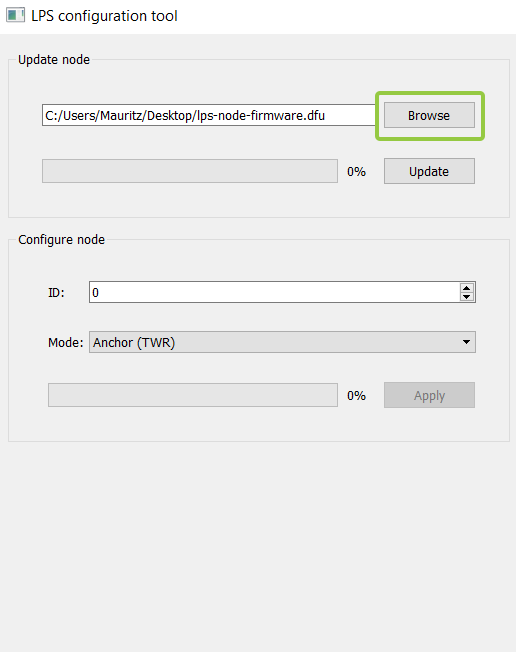
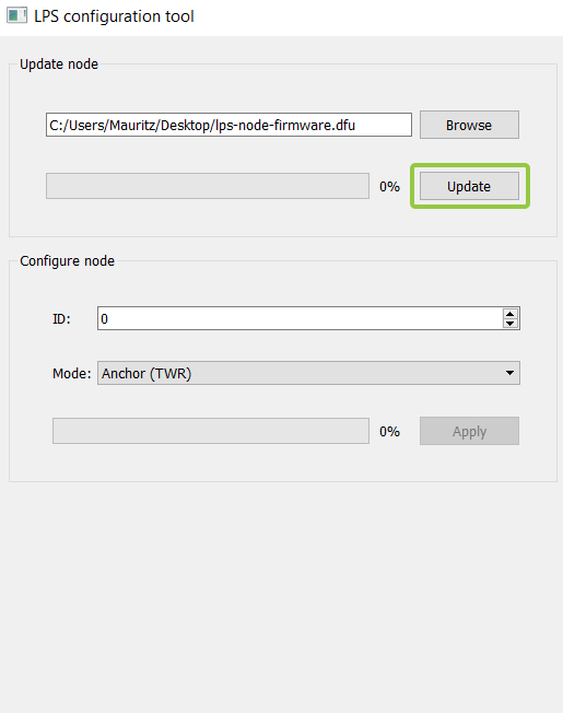
- Now update the node.
- When the update is done press reset.
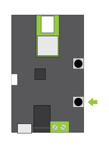
Disconnect the node from the USB and repeat the same procedure for all the nodes before configuring them.
Configuring the nodes into anchors
Now it’s time to set the mode for the nodes turning them into anchors, and setting the individual ids for each anchor. The anchors should be numbered from 0 and upwards.
Tip: to make it easy to identify the anchors and to manage the system in the future, it might be a good idea to mark the anchors with their ids.
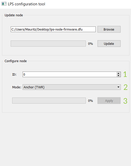
- Connect the first anchor to USB (without pressing any button)
- Select an appropriate ID
- Choose the “Anchor (TWR)” mode
- Click Apply to write the settings to the anchor
- Repeat the procedure for all anchors
Place the anchors in the room
Anchor positions
To get a good result there are some rules of thumb for the placement of the anchors:
- The anchors should be evenly distributed around the flying volume and at least 2m apart.
- The anchors should have line of site with the flying volume.
- The anchor antenna should be placed 15cm from any wall, ceiling or metal object to avoid interfering reflections. In our reference set-up we accomplish this by using these 3D printed stands. In the repository click “Raw” and then choose “save as” and save the file as a stl file.
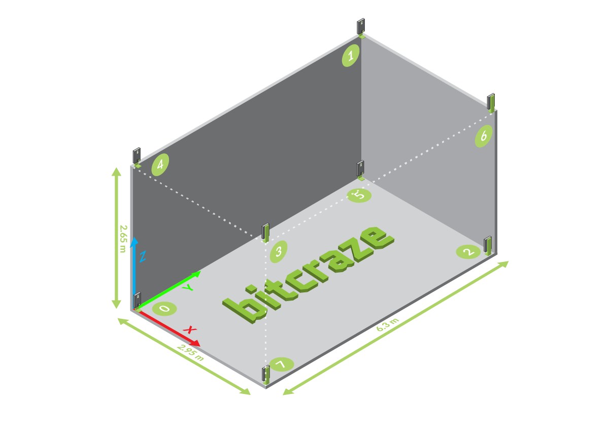
In our 8 anchor reference setup we have placed the nodes in the corners of a box as the position estimation for TDoA works best within the convex hull. The order of the IDs is important for TDoA2 but can be ignored for TDoA3.
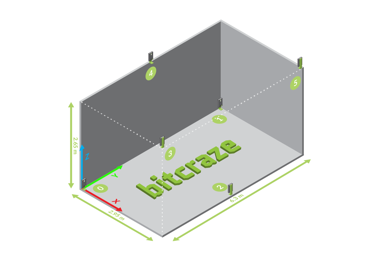
In our 6 anchor reference setup we have placed 3 anchors above and 3 anchors below the flight area, shaped in inverse triangles.
If you have more than 8 anchors, we suggest you setup a system with 8 anchors first and then switch your system to TDoA3 to add more anchors to the system. See the tdoa3 setup page for more information.
Powering the anchors
The anchor can be powered in three different ways.

- Micro USB. Good for fixed and portable setups were a external battery or power adapter is used.
- Barrel jack. Good for fixed and portable setup were power adapter is used.
- Screw terminal. Good for fixed installation and for chaining. Cable size up to 0,5mm2.
They can be connected at the same time so the anchor can still be power from the screw terminal when connecting the micro USB cable to do an update or when changing the configuration. All power options can handle 5-12V and the supply should be able to provide at least 150mA of current.
Configure and verify the system
The following section will show a 8 anchor system but the procedure is very similar for a 6 anchor setup were anchor 6 & 7 will be grayed out.
Open the Crazyflie client
Now when everything is mounted and powered it is time to configure the system, this is done from the Crazyflie client. Communication between the client and the anchors is relayed through the Crazyflie and the Loco Positioning deck.
- Place your Crazyflie 2.x in the center of the flying area.
- Open the CF client and connect to the Crazyflie 2.x
- If not already done, configure the Crazyflie 2.x in 2Mbit radio mode. This reduces interference with the UWB radio. If the configuration is changed a restart of the Crazyflie 2.x is required.
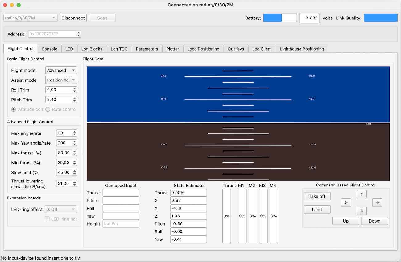
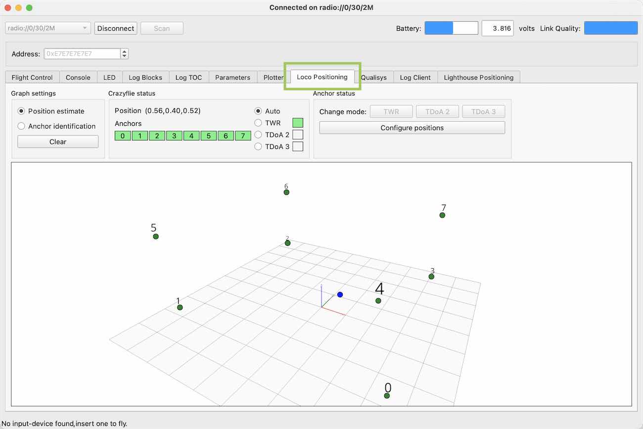
Click the Loco Positioning tab
Choose the Loco Positioning tab.
You may have to check it in the menu View->Tabs->Loco Positioning Tab to make it visible.
Check anchor status
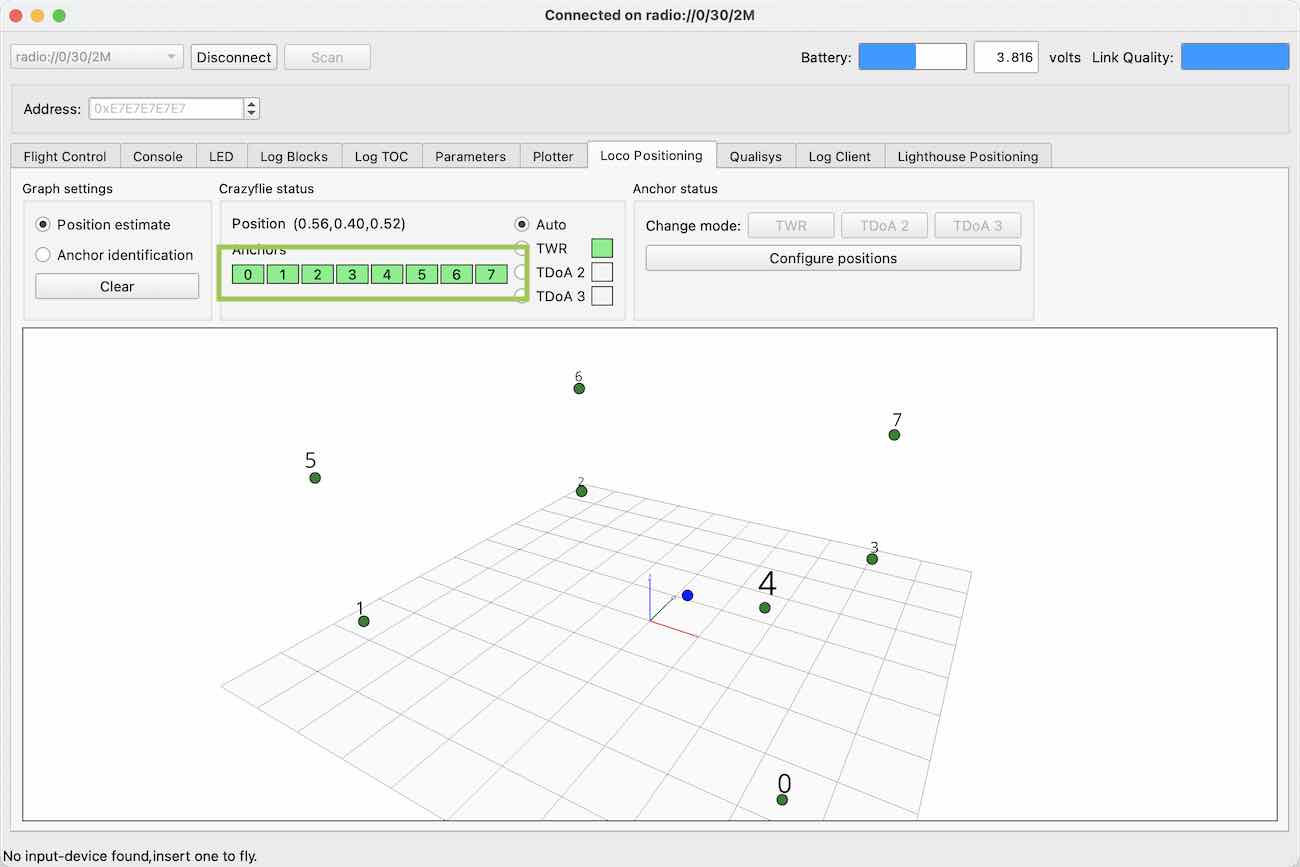
In the Anchor ranging status box, check that there are as many green boxes as there are anchors.
A red box indicates that the Crazyflie 2.x can not communicate with that anchor and does not get any ranging data. If this is the case, verify the anchor is configured correctly, powered and in line of sight.
Enter anchor positions
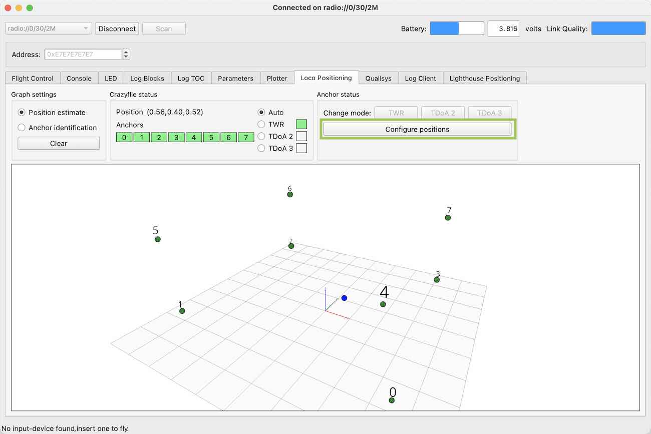
To start configuring the anchor position you need to click on the “Configure positions” button.
A pop-up window will appear. Click the button “Get from anchors” to get the list of anchors and fill up the positions with the values currently stored in the anchors.
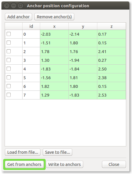
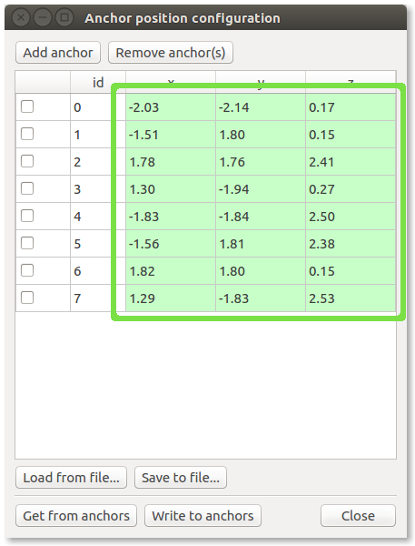
Anchors that do not already have a position stored will not appear in the list, in this case you have add them manually by clicking the “Add anchor” button.
Enter the positions (coordinates) of the anchors in your system. Note: measurements in meters.
When you enter a new value, the box turns red to indicate that it differs from the current value stored in the anchor.
Write position to anchors
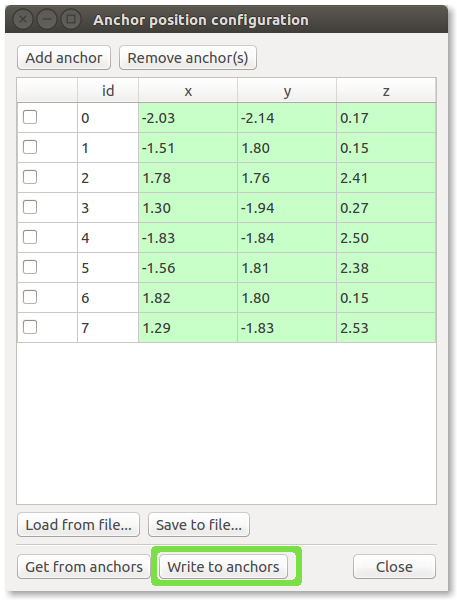
- To save the new anchor positions in the anchors press the “Write to anchors” button
- Verify that the anchor position boxes changes from red to green, which indiates that the new position has been written to the anchor and red back to the client. The read back process may take up to 5 seconds, please be patient. If no change has occurred after 5 to 10 seconds, the write did probably not work for all anchors, try to write again by clicking the “Write to anchors” button.
Verify anchor positions
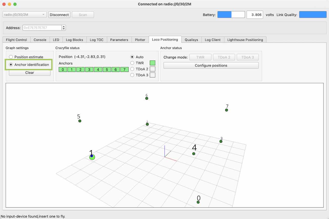
Verifying the anchor positions is good to rule out problems with the positioning later. The 3D graph shows the anchors and the position of the Crazyflie. The red line indicates the X-axis, green i the Y-axis and blue is the Z-axis. The Graph can be rotated, moved and scaled using the mouse.
- Switch the Graph Settings mode to “Anchor identification”
- Move the Crazyflie close to one anchor
- Verify that the correct anchor is indicated in the graph
- Repeat the procedure for all anchors and correct any wrongly configured anchor addresses
Verify estimated position
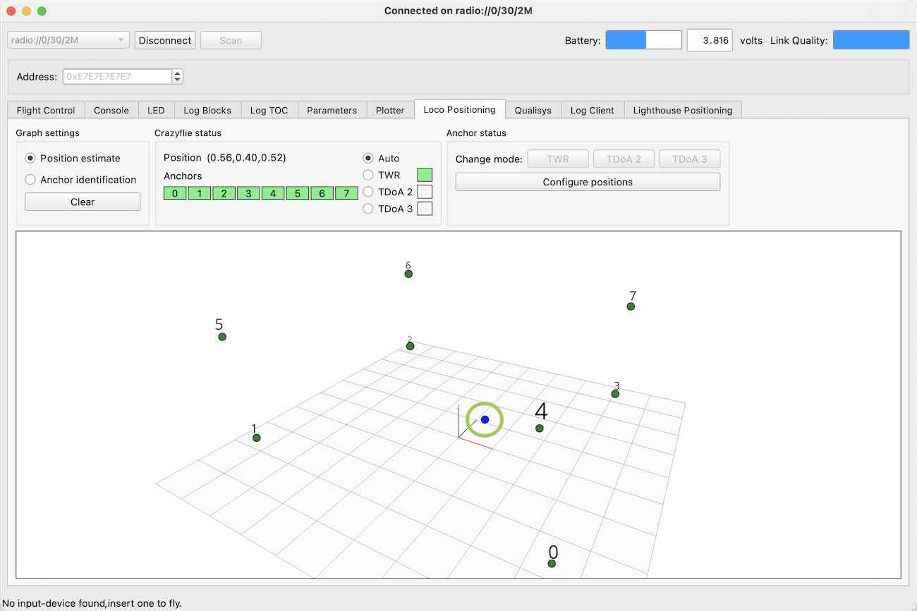
- Switch the Graph Settings mode back to “Position estimate”
- Move the CF around and verify that the movement in the graphs correspond to the physical movement
Calibration finished
Congratulations, the Loco Positioning System is now calibrated!
Switching system mode to TDoA
If you intend to use the system in TDoA mode to fly more than one Crazyflie it is now time to change the system mode. There exist two version of the TDoA ranging protocol.
- TDoA 2 works with 8 anchors.
- TDoA 3 is more robust and does not have any limitation in the number of anchors and so it can be used for bigger systems. The estimated position might be slightly more noisy compared to TDoA2.
Force the Crazyflie to use TWR mode
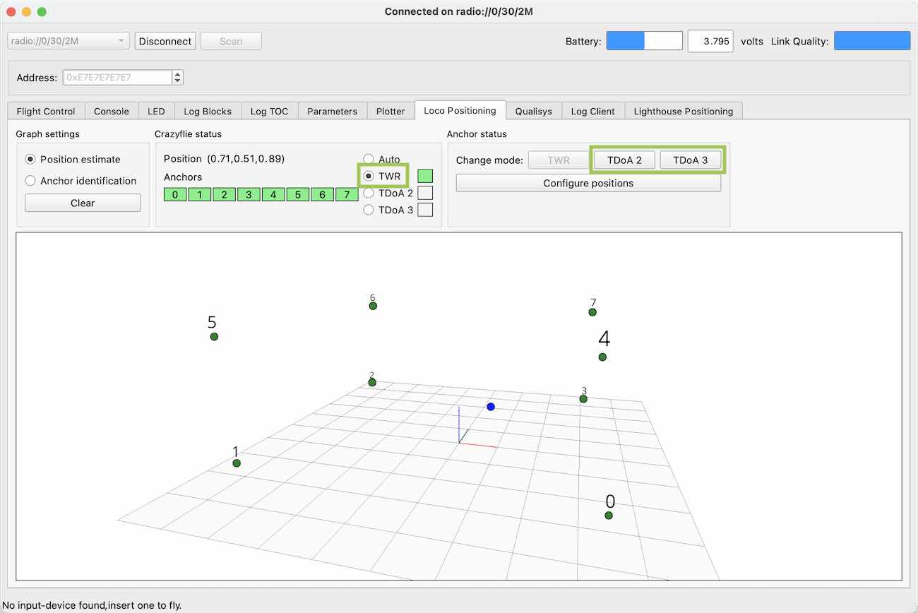
In the crazyflie status section tick the TWR radio button.
This will enable the “TDoA2” and “TDoA3” buttons in the anchor status section.
Switch anchors to TDoA mode
Click the “TDoA 2” or “TDoA 3” button to switch the anchors to one of the TDoA modes.
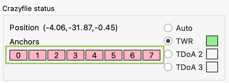
After a few seconds all anchor status boxes should turn red to indicate that the Crazyflie 2.x is no longer receiving TWR data from the anchors.
For details on system mode switching and troubleshooting, please see the documentation
Switch the Crazyflie back to auto mode
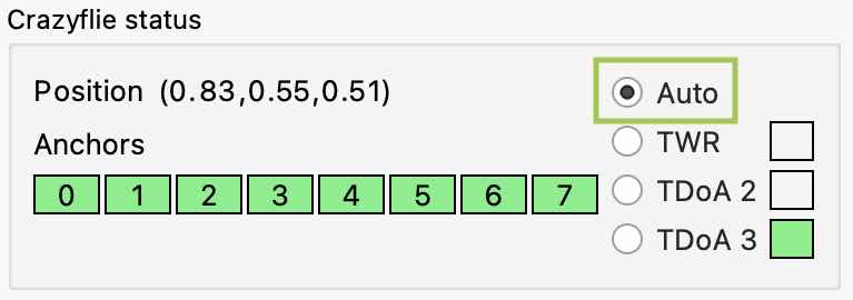
As a last step, confirm the TDoA mode by ticking the Auto radio button in the Crazyflie status section and verify that the TDoA2 box turns green.
The anchor boxes should also turn green when the Crazyflie switches to TDoA mode and starts to receive data from the anchors.
If not all anchor boxes go green, please see the documentation for touble shooting.
Next step
Now when you got the basic functionality of the system up and running you might want to try Getting started with Flying using Loco Positioning.
To read the more techy documentation go to the Loco positioning documentation page.