PID controller tuning
WARNING: When tuning the PID controller of a quadcopter, always take safety precautions. Secure the quadcopter in a safe environment to prevent accidents, as improper tuning can cause instability and unpredictable behavior. Use a tether or safety net, and wear protective gear to minimize risks. Make sure you have configured the emergency stop to a button on your controller.
Tuning a PID controller for a quadcopter is necessary for ensuring stable, responsive and precise flight control. For a custom-built quadcopter, for example using the Crazyflie Bolt, tuning becomes essential to adjust and optimize the drone’s performance according to the specific components and configurations used.
This tutorial provides fundamental PID tuning information aimed at beginners, covering essential concepts and step-by-step instructions. Additionally, it demonstrates specific tuning operations within our ecosystem, offering practical guidance that can also benefit advanced users.
Prerequisites
- Hardware
- Crazyflie 2.1, Crazyflie 2.0, or a custom-built quadcopter using the Crazyflie Bolt 1.1
- Crazyradio 2.0 or Crazyradio PA
- Optional: For tuning the velocity and position controllers, you need a positioning system such as the Lighthouse positioning system or the Flow deck v2.
- Recommended: a controller (e.g., PS3, Xbox, or a custom controller)
- Software
- Latest release of the cfclient
Make sure that you have gone through the how to get flying with a controller userguide before continuing with this tutorial.
Basic concept
The PID controller controls a process with three parameters; Proportional (P), Integral (I), and Derivative (D). It manages the process based on the error, which is the difference between a desired setpoint and the actual process value.
-
Proportional (P): This term produces an output that is proportional to the current error value. If the error is large, the control output is large, and if the error is small, the control output is small. It’s calculated as , where is the proportional gain and is the error at time .
-
Integral (I): This term is concerned with the accumulation of past errors. It integrates the error over time, which helps eliminate residual steady-state error. It’s calculated as , where is the integral gain.
-
Derivative (D): This term predicts future error based on its rate of change. It provides a damping effect, reducing the tendency to overshoot. It’s calculated as , where is the derivative gain.
The combined output of a PID controller is the sum of these three terms:
This output is used to adjust the process to achieve the desired setpoint.
The gains (Proportional Gain), (Integral Gain), and (Derivative Gain) are used to tune a PID controller:
- : Adjusts the responsiveness to the current error. Higher increases response speed but can cause overshoot.
- : Adjusts the response based on the accumulation of past errors. Higher eliminates steady-state error but can cause instability.
- : Adjusts the response based on the rate of error change. Higher provides damping, reducing overshoot and oscillations.
Tuning involves balancing these gains to achieve stable and accurate control.
Our firmware uses a cascaded PID controller structure, with separate controllers for attitude rate, attitude, velocity, and position.
Setup
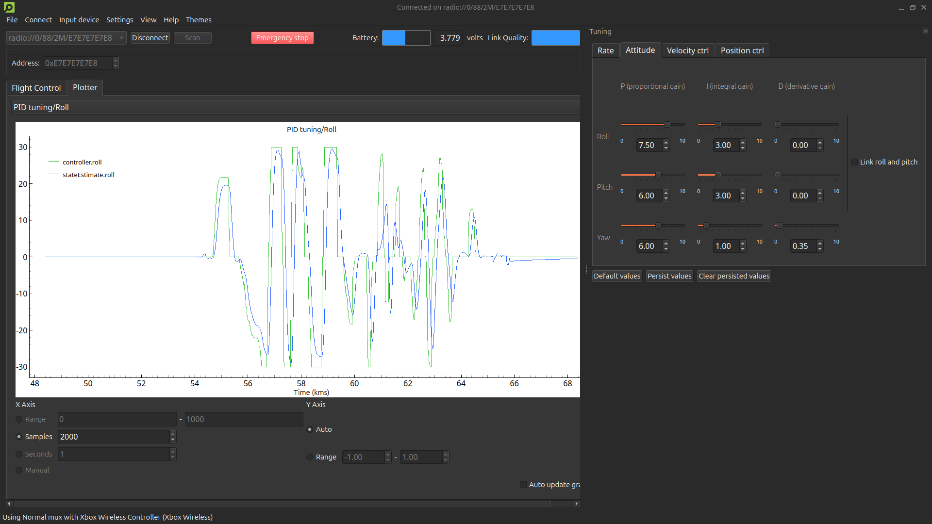
In this tutorial, we use cfclient to tune the PID controllers because it provides a comprehensive environment that allows us to simultaneously adjust PID gains, plot setpoints and state estimates, and control the drone with a controller or position setpoints.
To effectively tune each controller in the cascaded PID system, you must provide setpoints of the same order or higher than the respective controller’s level. For instance, position setpoints are necessary for tuning the position controller, while attitude, velocity or position setpoints suffice for the attitude controller. Attitude rate, attitude and velocity controllers are best made by conducting manual flight tests with a controller, as it allows for testing a variety of maneuvers. In this tutorial, we assume users will use a controller for manual flight tests. Setpoints can also be written and adjusted using other methods like through cflib or the app layer. However, using cflib to connect to the drone will prevent cfclient from connecting, so you cannot plot data or adjust gains directly from cfclient. Using the app layer can be cumbersome since it requires firmware flashing each time setpoints need adjustment, making the process more time-consuming.
Depending on what controller mode you will use to control your Crazyflie, it may be unnecessary to tune the higher level controllers.
- Open up cfclient
- Connect and configure your controller
- Connect to your Crazyflie
- Enable the plotter tab
- Enable the tuning toolbox
Basic PID Tuning
Set up the plotter to monitor both your desired setpoint and the estimated value of the controlled state. Adjust the gains in the tuning toolbox accordingly, observe the response in the plotter to fine-tune until the graphs of your desired setpoint and the estimated state align as closely as possible. WARNING: Do not change PID values while the drone is flying. Always land the drone before making adjustments.
Begin by tuning the attitude rate controller, then proceed to the attitude controller. These adjustments are best made after manual flight with a controller, as this allows you to fine-tune the PID controllers according to your specific flight preferences. Whether you prefer subtle inputs for a smooth flight, or you aim for a highly agile and responsive drone, manual flight testing enables you to tailor the tuning for the desired flight characteristics.
For tuning the velocity and position controllers some form of positioning system is required. The easiest method of tuning the velocity controller is to enable hover or position hold assisted control in the Flight Control tab. In these modes, velocity setpoints are automatically adjusted based on your controller inputs. Note that you must configure and hold a button on your controller to activate the assisted mode. For tuning the position controller we must send position setpoints. The most effective method for tuning this controller is by using the Command Based Flight Control in the Flight Control tab of the client.
Tips:
- Increase the number of samples or increase the logging period in the relevant logging configurations to extend the time window of the plot.
- Untick “Auto update graph” to pause the plotter and analyze the data.
- Tick “Link roll and pitch” to adjust the gains for both axes simultaneously. Roll and pitch can typically be tuned simultaneously due to symmetrical design of the Crazyflie.