brushless

Drones can perform a wide range of interesting tasks, from crop inspection to search-and-rescue. However, to make drones practically attractive they should be safe and cheap. Drones can be made safer by reducing their size and weight. This causes less damage in a collision with people or the environment. Additionally, being cheap means that the drones can take more risk – as it is less expensive to lose one – or that they can be deployed in larger numbers.

To function autonomously, such a drone should at least have some basic navigation capabilities. External position references such as GPS or UWB beacons can provide these, but such a reference is not always available. GPS is not accurate enough in indoor settings, and beacons require prior access to the area of operation and also add an additional cost.

Without these references, navigation becomes tricky. The typical solution is to have the drone construct a map of its local environment, which it can then use to determine its position and trajectories towards important places. But on tiny drones, the on-board computational resources are often too limited to construct such a map. How, then, can these tiny drones navigate? A subquestion of this – how to follow previously traversed routes – was the topic of my MSc thesis under supervision of Kimberly McGuire and Guido de Croon at TU Delft, and my PhD studies. The solution has recently been published in Science Robotics – “Visual route following for tiny autonomous robots” (TU Delft mirror here).

Route following

In an ideal world, route following can be performed entirely by odometry: the measurement and recording of one’s own movements. If a drone would measure the distance and direction it traveled, it could just perform the same movements in reverse and end up at its starting place. In reality, however, this does not entirely work. While current-day movement sensors such as the Flow deck are certainly accurate, they are not perfect. Every time a measurement is taken, this includes a small error. And in order to traverse longer distances, multiple measurements are summed, which causes the error to grow impractically large. It is this integration of errors that stops drones from using odometry over longer distances.

The trick to traveling longer distances, is to prevent this buildup of errors. To do so, we propose to let the drone perform ‘visual homing’ maneuvers. Visual homing is a control strategy that lets an agent return to a location where it has previously taken a picture, called a ‘snapshot’. In order to find its way back, the agent compares its current view of the environment to the snapshot that it took earlier. The trick here is that the difference between these two images smoothly grows with distance. Conversely, if the agent can find the direction in which this difference decreases, it can follow this direction to converge back to the snapshot’s original location.

The difference between images smoothly increases with their distance.

So, to perform long-distance route following, we now command the drone to take snapshots along the way, in addition to odometry measurements. Then, when retracing the route, the drone will routinely perform visual homing maneuvers to align itself with these snapshots. Because the error after a homing maneuver is bounded, there is now no longer a growing deviation from the intended path! This means that long-range route following is now possible without excessive drift.

Implementation

The above mentioned article describes the strategy in more detail. Rather than repeat what is already written, I would like to give a bit more detail on how the strategy was implemented, as this is probably more relevant for other Crazyflie users.

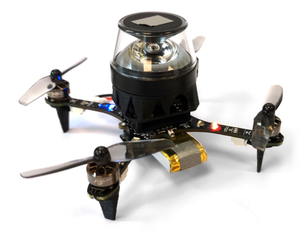
The main difference between our drone and an out-of-the-box one, is that our drone needs to carry a camera for navigation. Not just any camera, but the method under investigation requires a panoramic camera so that the drone can see in all directions. For this, we bought a Kogeto Dot 360. This is a cheap aftermarket lens for an older iPhone that provides exactly the field-of-view that we need. After a bit of dremeling and taping, it is also suitable for drones.

ARDrone 2 with panoramic camera lens.

The very first visual homing experiments were performed on an ARDrone 2. The drone already had a bottom camera, to which we fitted the lens. Using this setup, the drone could successfully navigate back to the snapshot’s location. However, the ARDrone 2 hardly qualifies as small as it is approximately 50cm wide, weighs 400 grams and carries a Linux computer.
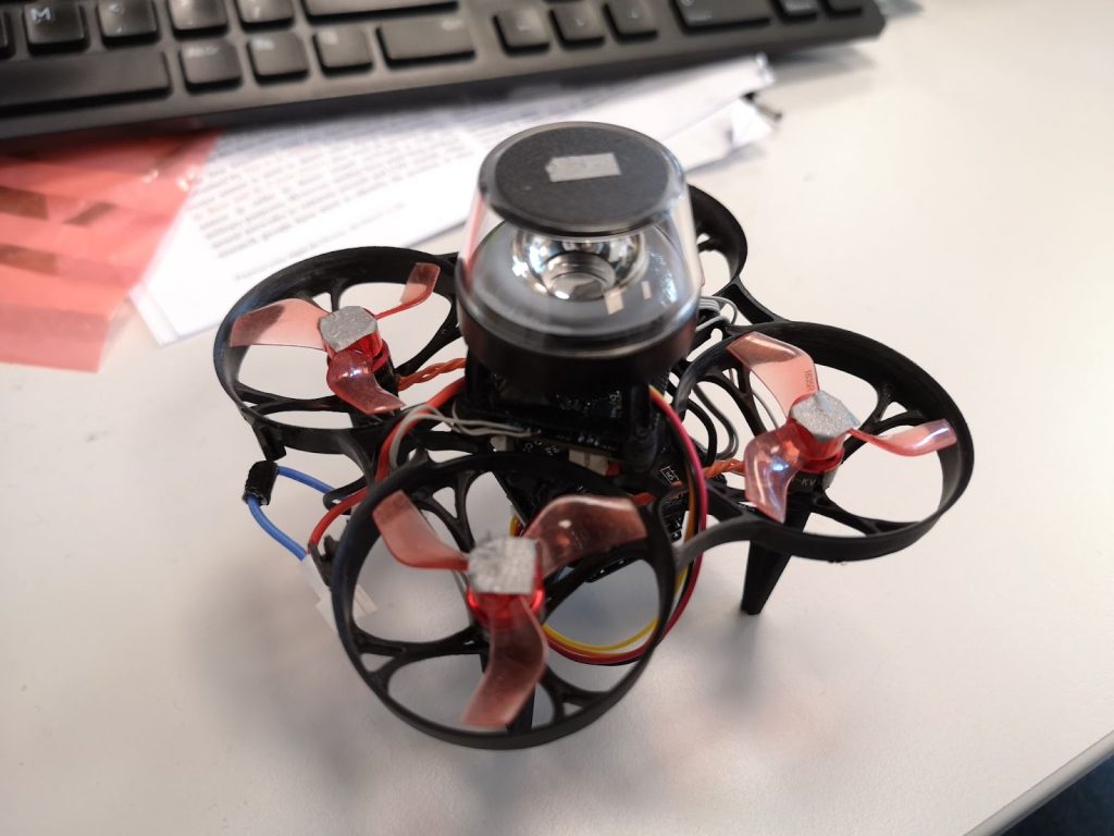
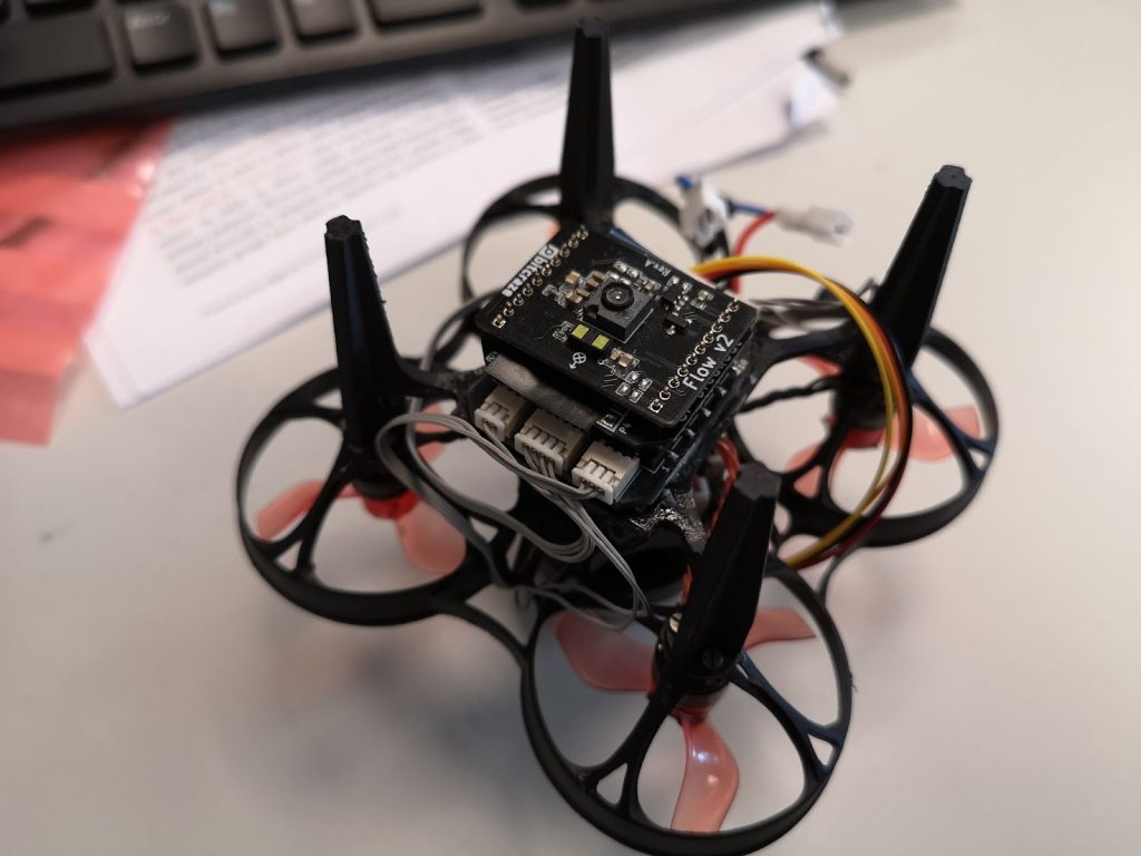
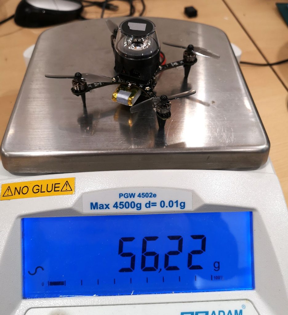
To prove that the navigation method would indeed work on tiny drones, the setup was downsized to a Crazyflie 2.0. While this drone could take off with the camera assembly, it would become unstable very soon as the battery level decreased. The camera was just a bit too heavy. Another attempt was made on an Eachine Trashcan, heavily modified to support both the camera, a flowdeck and custom autopilot firmware. While this drone had more than enough lift, the overall reliability of the platform never became good enough to perform full flight experiments.

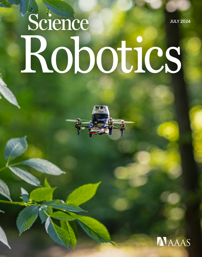
After discussing the above issues, I was very kindly offered a prototype of the Crazyflie Brushless to see if it would help with my experiments. And it did! The Crazyflie brushless has more lift than the regular platform and could maintain a stable attitude and height while carrying the camera assembly, all this, with a reasonable flight time. Software-wise it works pretty much the same as the regular Crazyflie, so it was a pleasure to work with. This drone became the one we used for our final experiments, and was even featured on the cover of the Science Robotics issue.
With the hardware finished, the next step was to implement the software. Unlike the ARDrone 2 which had a full Linux system with reasonable memory and computing power, the Crazyflie only has an STM32 microcontroller that’s also tasked with the flying of the drone (plus an nRF SoC, but that is out of scope here). The camera board developed for this drone features an additional STM32. This microcontroller performed most of the image processing and visual homing tasks at a framerate of a few Hertz. However, the resulting guidance also has to be followed, and this part is more relevant for other Crazyflie users.

To provide custom behavior on the Crazyflie, I used the app layer of the autopilot. The app layer allows users to create custom code for the autopilot, while keeping it mostly decoupled from the underlying firmware. The out-of-tree setup makes it easier to use a version control system for only the custom code, and also means that it is not as tied to a specific firmware version as an in-tree process.

The custom app performs a small number of crucial tasks. Firstly, it is responsible for communication with the camera. Communication with the camera was performed over UART, as this was already implemented in the camera software and this bus was not used for other purposes on the Crazyflie. Over this bus, the autopilot could receive visual guidance for the camera and send basic commands, such as the starting and stopping of image captures. Pprzlink was used as the UART protocol, which was a leftover from the earlier ARDrone 2 and Trashcan prototypes.

The second major task of the app is to make the drone follow the visual guidance. This consisted of two parts. Firstly, the drone should be able to follow visual homing vectors. This was achieved using the Commander Framework, part of the Stabilizer Module. Once the custom app was started, it would enter an infinite loop which ran at a rate of 10 Hertz. After takeoff, the app repeatedly calls commanderSetSetpoint to set absolute position targets, which are found by adding the latest homing vector to the current position estimate. The regular autopilot then takes care of the low-level control that steers the drone to these coordinates.

The core idea of our navigation strategy is that the drone can correct its position estimate after arriving at a snapshot. So secondly, the drone should be able to overwrite its position estimate with the one provided by the route-following algorithm. To simplify the integration with the existing state estimator, this update was implemented as an additional position sensor – similar to an external positioning system. Once the drone had converged to a snapshot, it would enqueue the snapshot’s remembered coordinates as a position measurement with a very small standard deviation, thereby essentially overwriting the position estimate but without needing to modify the estimator. The same trick was also used to correct heading drift.

The final task of the app was to make the drone controllable from a ground station. After some initial experiments, it was determined that fully autonomous flight during the experiments would be the easiest to implement and use. To this end, the drone needed to be able to follow more complex procedures and to communicate with a ground station.

Because the cfclient provides most of the necessary functions, it was used as the basis for the ground station. However, the experiments required extra controls that were of course not part of a generic client. While it was possible to modify the cfclient, an easier solution was offered by the integrated ZMQ server. This server allows external programs to communicate with the stock cfclient over a tcp connection. Among the possibilities, this allows external programs to send control values and parameters to the drone. Since the drone would be flying autonomously and therefore low-frequencies would suffice, the choice was made to let the ground station set parameters provided by the custom app. To simplify usability, a simple GUI was made in python using the CFZmq library and Tkinter. The GUI would request foreground priority such that it would be shown on top of the regular client, making it easy to use both at the same time.

Cfclient with experimental overlay (bottom right).

To perform more complex experiments, each experiment was implemented as a state machine in the custom app. Using the (High-level) Commander Framework and the navigation routines described above, the drone was able to perform entire experiments from take-off to landing.

While the code is very far from production quality, it is open source and can be viewed here to see how everything was implemented: https://github.com/tomvand/2020-visualhoming-crazyflie . The PCB used to fit Crazyflie decks to the Eachine Trashcan can be found here: https://github.com/tomvand/cf-deck-carrier .

Outcome

Using the hardware and software described above, we were able to perform the route-following experiments. The drone was commanded to fly a preprogrammed trajectory using the Flow deck, while recording odometry and snapshot images. Then, the drone was commanded to follow the same route in reverse, by traveling short sections using dead reckoning and then using visual homing to correct the incurred drift.

As shown in the article, the error with respect to the recorded route remained bounded. Therefore, we can now travel long routes without having to worry about drift, even under strict hardware limitations. This is a great improvement to the autonomy of tiny robots.

I hope that this post has given a bit more insight into the implementation behind this study, a part that is not often highlighted but very interesting for everyone working in this field.
We are happy to announce that release 2024.10 is now available! Special thanks to our community contributors for their valuable input and code contributions in this release!

Release overview

crazyflie-firmware release 2024.10 GitHub

crazyflie2-nrf-firmware release 2024.10 GitHub

crazyflie2-nrf-bootloader release 2024.10 GitHub

cfclient (crazyflie-clients-python) release 2024.10 GitHub, PyPI

cflib (crazyflie-lib-python) release 0.1.27 on GitHub, PyPI

User upgrade notice

While older versions may still function, users are encouraged to upgrade:

  • Minimum supported Python version changed to 3.10
  • Supported Ubuntu versions changed to 22.04 and 24.04

Major changes

  • Enhanced out-of-tree (OOT) kbuild configuration, allowing users to perform full Kconfig configuration for app layer applications.
  • Introduced recovery functionality, allowing users or scripts to safely re-enable the system after a crash without reboot.
  • Added a timeout for auto-disarming, allowing the system to remain armed during brief landings in manual arming mode.
  • Introduced a workaround for PID derivative kick, improving the performance of the PID controller during large setpoint changes (#1337, #1403).
  • Spiral and constant velocity high-level commander segments (#1410).
  • Changed BLE name format to include part of the NRF MAC address, allowing users to easily differentiate between Crazyflies.

For detailed release notes, check out the individual releases on GitHub. Links can be found in the release overview above.

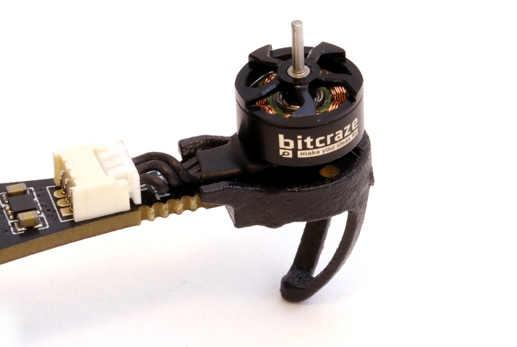
For the upcoming Crazyflie 2.1 brushless we developed, together with a leading motor manufacturing brand, a brushless 08028 motor, targeting high quality and high efficiency. The 08 – stator size motors are usually optimized for high power output, to serve the FPV market, but we where aiming for high efficiency. This means fitting maximum amount of copper around the stator, lowering KV, thin stator lamination sheets and high quality dual ball-bearings.

Specification

  • Stator size: 08028 (8.4mm x 2.8mm)
  • Stator lamination sheets: 0.2mm
  • Motor KV: 10000
  • Internal resistance: 0.52 Ohm
  • Weight: 2.4g
  • Dual ball-bearing design, using high quality NSK or NMB brands.
  • 1 mm shaft, 5 mm length
  • Matching propeller: Bitcraze 55-35mm
  • Peak current 1.8A, peak power 7.2W -> 30g thurst @ 4V (using 55-35)
  • Rated voltage: 4.2V

Together with the bitcraze 55-35 mm propeller we manage to achieve a system efficiency of over 5 W/g during hover, not to shabby. As a reference, FPV setups normally achieve around 2 W/g. This will bring the hover time for the Crazyflie 2.1 brushless, in the barebone configuration, a bit over 10 minutes.

It is easy to forget that the reason why it is nice to develop for the Crazyflie is because it weighs only about 30 grams. In case something goes wrong with your script or there is a fly-away, you can simply pick it up from the air without worrying about the propellers hitting you. Moreover, when the Crazyflie crashes, it usually only requires a brush off and a potential replacement of a motor-mount or propeller. The risk of damage to yourself, other people, indoor furniture, or the vehicle itself is extremely low. However, things become very different if you’ve built a larger platform with the Bolt or BQ deck with large brushless motors (like with this blogpost), where the risk of injury to people or to the vehicle itself increases significantly. That is one of the major reasons why the BQ deck and the Bolt are still in early access and have been for a while. In our efforts to get it out of early access, it’s time to start thinking about safety features.

In this blog post, we’ll be discussing how other open-source autopilot programs are implementing safety features, followed by a discussion on current efforts for Crazyflie, along with an announcement of the developer meeting scheduled for May 3rd (see below for more info).

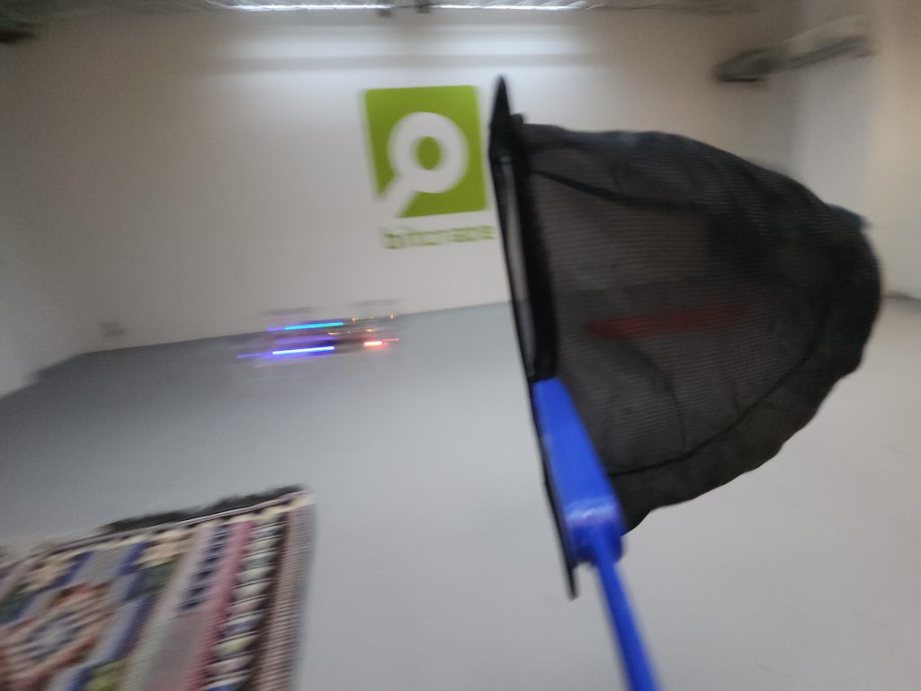
Catching the Crazyflie with a net

Safety in other Autopilots

We are a bit late to the game in terms of safety compared to other autopilot programs such as PX4, ArduPilot, Betaflight and Paparazzi UAV, which have been thinking about safety for quite some time. It makes a lot of sense when you consider the types of platforms that run these autopilots, such as large fixed VTOL or fixed-wing vehicles or 10-kilo quadcopters with cinematic cameras, or the degree of outdoor flight regulation. Flying a UAV autonomously or by yourself has become much more challenging as the US, EU, and many other countries have made it more restrictive. In most cases, you are not even allowed to fly if fail-safes are not implemented, such as what to do if your vehicle loses GPS signal. These types of measures can be separated into pre-flight checks and during-flight checks.

Pre-flight checks

Before a vehicle is allowed to fly, or even before the motors are allowed to spin, which is called ‘arming’, several conditions must be met. First, it needs to be checked if all internal sensors, such as the IMU, barometer, and magnetometer, are calibrated and functional, so they don’t give values outside of their normal operating range. Then, the vehicle must receive a GPS signal, and the internal state estimator (usually an extended Kalman filter) should converge to a position based on that information. It should also be determined if an external remote control is connecting to the vehicle and if there is any datalink to a ground station for telemetry. Feasibility checks can also be implemented, such as ensuring that the mission loaded to the UAV is not outside its mission parameters or that the start location is not too far away from its take-off position (assuming the EKF is functional). Additionally, the battery should not be low, and the vehicle should not still be in an error state from a previous flight or crash.

All of these features have the potential to be turned off or made less restrictive, depending on your situation. However, keep in mind that changing any of these may require recertification of the drone or make it fall outside what is required for outdoor flight regulation. Therefore, these should only be changed if you know what you are doing.

Preflight checks documentation

Fail-safe triggers during flight

Now that the pre-flight checks have passed, the UAV is armed and you have given it the takeoff command. However, there is so much more that can go wrong during a UAV flight, and takeoff is one of the most dangerous moments where everything could go wrong. Therefore, there are many more safety features, aka failsafes, during the flight than for the pre-flight checks. These can also be separated into ‘triggers’ and ‘behaviors,’ so that the developer can choose what the UAV should do in case of a failure, such as ‘GPS loss’ to ‘land safely’ and so on.

Thus, there are triggers that can enable the autopilot’s failsafe mechanics:

  • No connection with the remote control
  • No connection with the Ground station or Datalink
  • Low Battery
  • Position estimate diverges or full GPS loss
  • Waypoint going beyond geofence or Mission is not feasible
  • Other vehicles are nearby.

Also, sometimes the support of an external Automatic Trigger system is required, which is a box that monitors the conditions where the UAV should take action in case there is no GPS, other aerial vehicles are nearby, or the UAV is crossing a geofence determined by outdoor flight restrictions. Note that all of these triggers usually have a couple of conditions attached, such as the level of the ‘low battery’ or the number of seconds of ‘GPS loss’ deemed acceptable.

Fail-safe behavior

If any of the conditions mentioned above are triggered, most autopilot suites have some failsafe behaviors linked to those set by default. These behaviors can include the following:

  • No action at all
  • Warning on the console or remote control display
  • Continue the mission autonomously
  • Stay still at the same position or go to a home position
  • Fly to a lower altitude
  • Land based on position or safely land by reducing thrust
  • No input to motors or completely disarming the motors

Usually, these actions are set in regulation, but per trigger, it is possible to give a different behavior than the default. One can decide to completely disarm the vehicle, but then the chances of the UAV crashing are pretty high, which can result in damage to the vehicle or cause harm to people or objects. By the way: disarming is the opposite act of arming, which is not allowing the motors to spin, no matter if it is receiving an input. If you decide to never do anything and force the drone to finish the mission autonomously, then in a case of GPS or position loss, you risk losing your vehicle or that it will end up in areas where it is absolutely not allowed, such as airports. Again, changing these default behaviors should be done by someone who knows what they are doing, and it should be done with careful consideration.

Failsafe documentation other autopilot suites:

Emergencies

Fail-safes are measures that ensure safe flight. However, there will always be a chance that an emergency will occur, which will require an immediate action as well. If the vehicle has crashed during any of its phases or has flipped, or if the hardware breaks, such as the motors, arms, or perhaps even the autopilot board itself, what should be done then?

The standard default behavior for this is to completely disarm the vehicle so that it won’t react to any input to the motors itself. Of course, it’s difficult to do if the autopilot program is on, but at least it won’t try to take off and finish its mission while laying on its side. It might be that a backup system is connected to the ESCs that will take over in case the autopilot is not responding anymore, perhaps using a different channel of communication.

Also, the most important safety feature of all is the pilot itself. Each remote control should have a special button or switch that can put the drone in a different mode, make it land, or disarm it so that the pilot can act upon what they see. In case the motors are still spinning, have a net or towel available to throw over them, disconnect the battery as soon as possible, and make sure to have sand or a special fire retardant in case the LiPo batteries are pierced.

All of the autopilots have some tips to deal with such situations, but make sure to do some good research yourself on how to handle spinning parts or potential LiPo battery fires. I’m just giving a compilation of tips given in the documentation above here, but please make sure to read up in detail!

Safety in the Crazyflie Firmware

So how about the Crazyflie-firmware ? We have some safety features build in here and there but it is all over the code base. Since the Crazyflie is so safe, there was no immediate need for this and we felt it is more up to the developer to integrate it themselves. But with the Bolt and BQ deck coming out of early access, we want to at least do something. As we started already started looking into how other autopilot softwares are doing it, we can get some ideas, however we did notice that many of these are mostly meant for outdoor flight. The Crazyflie and the Crazyflie Bolt have been designed for indoor use and perhaps deal with different issues as well.

Current safety features

This is a collection of safety features currently in the firmware at the time of writing this blogpost. Most safety features in the Crazyflie are up for the developer to double check before and during flight, but these are some automatic once that are scattered around the firmware:

However, if for instance your Crazyflie or Bolt platform loses its positioning in air, or doesn’t have a flowdeck attached before takeoff, there are no default safety systems in check. You either need to catch it, make it land or use an self-made emergency stop button using one of the emergency stop services above.

Safety features in works

As mentioned earlier, we have safety features spread throughout the code base of the Crazyflie firmware. Our current effort is to collect all of these emergency stops and triggers in the supervisor module to have them all in one place.

In addition, since indoor positioning is critical, we want to be notified when it fails. For instance, if the lighthouse geometry is incorrect, we need to see if the position diverges. This check was done outside of the Crazyflie firmware in a cflib script, but it has not been implemented inside the firmware. We also want to provide some options in terms of behavior for these triggers. Currently, we are working on two options: ‘turn the motors off’ or ‘safe land,’ with ‘safe land’ decreasing the thrust while keeping the drone level in attitude.

Furthermore, we want to integrate these features into the cfclient as well. For example, we want to add more emergency safety features to our remote control through the cfclient, and show users how to arm and disarm the vehicle.

These are the elements we are currently working on, but there might be more to come!

Developer meeting May 3rd

You probably already guessed it… the topic about the next developer meeting will be about the safety features in the Crazyflie and the Bolt! We will present the current safety features in the Crazyflie and what we are currently working on to make it better. In this sense, we really want to have your feedback on what you think is important for brushless versions of the Crazyflie for indoor flight!

The Dev meeting will be on Wednesday May the 3rd at 3 PM CEST. Please keep an eye on the discussion forum in the developer meeting thread.