crazyflie

A while ago, we wrote a generic blog post about state estimation in the Crazyflie, mostly discussing different ways the Crazyflie can determine its attitude and/or position. At that time, we only had the Complementary filter and Extended Kalman filter (EKF). Over the years, we’ve made some great additions like the M-estimation-based robust Kalman filter (an enhancement of the EKF, see this blog post) and the Unscented Kalman filter.

However, we have noticed that some of our beginning users struggle with understanding the concept of Kalman filtering, depending on whether this has been covered in their curriculum. And for some more experienced users, it might be nice to have a recap of the basics as well, since this is a very important part of the Crazyflie’s capabilities of flight (and also for robotics in general). So, in this blog post, we will explain the principles of Kalman filtering and how it is applied within the Crazyflie firmware, which hopefully will provide a good base for anyone starting to delve into state estimation within the Crazyflie.

We will also have a developer meeting about Kalman filtering on the Crazyflie, so we hope you can join that as well if you have any questions about how it all works. Also we are planning to got to FOSdem this weekend so we hope to see you there too.

Main Principles of the Kalman Filter

Anybody remotely working with autonomous systems must, at one point, have heard of the Kalman filter, as it has existed since the 60s and even played a role in the Apollo program. Understanding its main principles is also important for anyone working with drones or robotics. There are plenty of resources available, and its Wikipedia page is filled with examples, so here we will focus mostly on the concept and principles and leave the bulk of the mathematics as an exercise for those who like to delve into that :).

So basically, there are several principles that apply to a Kalman filter:

  • It estimates a linear system that is driven by stochastic processes. The probability function that drives these stochastic processes should ideally be Gaussian.
  • It makes use of the Bayes’ rule, which is a general term in statistics that describes the probability of an event happening based on previous knowledge related to that event.
  • It assumes that the ‘to be estimated state’ can be described with a Markov model, which assumes that a sequence of the next possible event (or scenario) can be predicted by the current event. In other words, it does not need a full history of events to predict the next step(s), only the information from the event of one previous step.
  • A Kalman filter is described as a recursive filter, which means that it reuses (part of) its output as input for the next filtering step.

So the state estimate is usually a vector of different variables that the developer or user of the system likes to observe, for either control or prediction, something like position and velocity, for instance: [x, y, , ẏ, …]. One can describe a dynamics model that can predict the state in the next step using only the current time step’s state, like for instance: xt+1 = xt + t, yt+1 = yt + ẏt. This can also be nicely described in matrix form as well if you like linear algebra. To this model, you can also add predicted noise to make it more realistic, or the effect of the input commands to the system (like voltage to motors). We will not go into the latter in this blogpost.

The Concept of Kalman filters

Simplified block scheme of Kalman filtering

So, we will go through the process of explaining the steps of the Kalman filter now, which hopefully will be clear with the above picture. As mentioned before, we’d like to avoid formulas and are oversimplifying some parts to make it as clear as possible (hopefully…).

First, there is the predict phase, where the current state (estimate) and a dynamics model (also known as the state transition model) result in a predicted state. Also in the same phase, the predicted estimated covariance is calculated, which also uses the dynamics model plus an indication of the process noise model, indicating how much the dynamics model deviates from reality in predicting that state. In an ideal world and with an ideal model, this could be enough; however, no dynamics model is perfect, which is why the next phase is also very important.

Then it’s the update phase, where the filter estimate gets updated by a measurement of the real world through sensors. The measurement needs to go through a measurement model, which transforms the measurement into a measured state (also known as innovation or measurement pre-fit residual). Usually, a measurement is not a 1-1 depiction of one variable of the state, so the measurement model ensures that the measurement can properly be compared to the predicted state. This same measurement model, accompanied by the measurement noise model (which indicates how much the measurement differs from the real world), together with the predicted covariance, is used to calculate the innovation and Kalman gain.

The last part of the update phase is where the predictions are updated with the innovation. The Kalman gain is then used to update the predicted state to a new estimated state with the measured state. The same Kalman gain is also used to update the covariance, which can be used for the next time step.

An 1D example, height estimation

It’s always good to show the filter in some form of example, so let’s show you a simple one in terms of height estimation to demonstrate its implications.

1D example of height estimation

You see here a Crazyflie flying, and currently it has its height estimated at zt and its velocity at żt. It goes to the predict phase and predicts the next height to be at zt+1,predict, which is a simple model of just zt + żt. Then for the innovation and updating phase, a measurement (from a range sensor) rz is used for the filter, which is translated to zt+1, meas. In this case, the measurement model is very simple when flying over a flat surface, as it probably is only a translation addition of the sensor to the middle of the Crazyflie, or perhaps a compensation for a roll or pitch rotation.

In the background, the covariances are updated and the Kalman gain is calculated, and based on zt+1,predict and zt+1, meas, the next state zt+1 is calculated. As you probably noticed, there was a discrepancy between the predicted height and measured height, which could be due to the fact that the dynamics model couldn’t correctly predict the height. Perhaps a PID gain was higher than expected or the Crazyflie had upgraded motors that made it climb faster on takeoff. As you can see here, the filter put the estimated height closer to zt+1 to the measurement than the predicted height. The measurement noise model incorporated into the covariances indicates that the height sensor is more accurate than the height coming from the dynamics model. This would very well be the case for an infrared height sensor like the one on the Flow Deck; however, if it were an ultrasound-based sensor or barometer instead (which are much noisier), then the predicted height would be closer to the one predicted by the dynamics model.

Also, it’s good to note that the dynamics model does not currently include the motor input, but it could have done so as well. In that case, it would have been better able to predict the jump it missed now.

A 2D example, horizontal position

A 2D example in x and y position

Let’s take it up a notch and add an extra dimension. You see here now that there is a 2D solution of the Crazyflie moving horizontally. It is at position xt, yt and has a velocity of t, ẏt at that moment in time. The dynamics model estimates the Crazyflie to end up in the general direction of the velocity factor, so it is a simple addition of the current position and velocity vector. If the Crazyflie has a flow sensor (like on the Flow Deck), flow fx, fy can be detected and translated by the measurement model to a measured velocity (part of the state filter) by combining it with a height measurement and camera characteristics.

However, the measurement in the form of the measured flow fx, fy estimates that there is much more flow detected in the x-direction than in the y-direction. This can be due to a sudden wind gust in the y-direction, which the dynamics model couldn’t accurately predict, or the fact that there weren’t as many features on the surface in the y-direction, making it more difficult for the flow sensor to measure the flow in that direction. Since this is not something that both models can account for, the filter will, based on the Kalman gain and covariances, put the estimate somewhere in between. However, this is of course dependent on the estimated covariances of both the outcome of the measurement and dynamic models.

In case of non-linearity

It would be much simpler if the world’s processes could be described with linear systems and have Gaussian distributions. However, the world is complex, so that is rarely the case. We can make parts of the world more abstract in simulation, and Kalman filters can handle that, but when dealing with real flying vehicles, such as the Crazyflie, which is considered a highly nonlinear system, it needs to be described by a nonlinear dynamics model. Additionally, the measurements of sensors in more complex and 3D situations usually don’t have a one-to-one linear relationship with the variables in the state. Can you still use the Kalman filter then, considering the earlier mentioned principles?

Luckily certain assumptions can be made that can still make Kalman filters useful in the sense of non-linearity.

  • Extended Kalman Filter (EKF): If there is non-linearity in either the dynamics model, measurement models or both, at each prediction and update step, these models are linearized around the current state variables by calculating the Jacobian, which is a collection of first-order partial derivative calculations of the model and the state variables.
  • Unscented Kalman Filter (UKF): An unscented Kalman filter deals with linearities by selecting sigma points selected around the mean of the state estimate, which are backpropagated through the non-linear dynamics model.

However, there is also the case of non-Gaussian processes in both dynamics and measurements, and in that case a complementary filter or particle filter would be best suited. The Crazyflie contains a complementary filter (which does not estimate x and y), an extended Kalman filter and an experimental unscented Kalman filter. Check out the state-estimation documentation for more information.

So…. where is the code?

This is all fine and dandy, however… where can you find all of this in the code of the Crazyflie firmware? Here is an overview of where you can find it exactly in the sense of the most used filter of them all, namely the Extended Kalman Filter.

There are several assumptions made and adjustments made to the regular EKF implementation to make it suitable for flight on the Crazyflie. For those details I’d like to refer to the papers on where this implementation is based on, which can be found in the EKF documentation. Also for a more precise explanation of Kalman filter, please check out the lecture slides of Stanford University on Linear dynamical systems or the Linköping university’s course slides on Sensor Fusion.

Update: From the comments we also got notified of an nice EKF tutorial where you write the filter from scratch (github) from Prof. Simon D. Levy from Washington and Lee university. Practice makes perfect!

Next Developer meeting and FOSdem

As you would have guessed, our next developer meeting will be about the Kalman filters in the Crazyflie. Keep an eye on this Discussion thread for more details on the meeting.

Also Kimberly and Arnaud will be attending FOSdem this weekend in Brussels, Belgium. We are hoping to organize an open-source robotics BOF/meetup there, so please let us know if you are planning to go as well!

Today we have a guest blogpost by Thomas Izycki (Technische Hochschule Augsburg) and Klaus Kefferpütz (Ingolstadt Technical University of Applied Sciences, former Augsburg Technical University of Applied Sciences) talking about implementing Software-in -the-Loop for swarm simulation of the Crazyflie.

When our cooperative control lab at the Technical University of Applied Sciences Augsburg was founded a few years ago, our goal was to develop distributed algorithms for teams of UAVs. We quickly decided to use Crazyflies with the algorithms directly implemented in the firmware, thus having a platform for a truly decentralized system. Our ongoing projects focus on cooperative path planning, navigation, and communication.

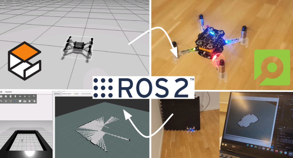
Since working with several drones at once, which have to communicate and coordinate with each other, can quickly become confusing and very time-consuming, a simulation was needed. It should preferably offer the possibility to integrate the firmware directly in the simulation environment and ideally also offer an interface to the crazyflie python API. With the relocation of our laboratory from Augsburg to the Technical University of Applied Sciences Ingolstadt, which however does not yet have a permanently established flying space, the need for a simulation environment was further increased in order to be less dependent on hardware accessibility. A look at the community and the available simulations quickly led us to the sim_cf flight simulator for the Crazyflie. A fantastic project supporting the use of the actual Crazyflie firmware in software-in-the-loop (SITL) mode and even in hardware-in-the-loop (HITL) mode on a real Crazyflie using the FreeRTOS Linux Port together with ROS and Gazebo. Unfortunately, the project has not been maintained for several years and also had no integration with the Crazyflie Python API. After a short chat with Franck Djeumou and his agreement to use the code of the original sim_cf simulation, the project was ready for an upgrade.

sim_cf2 Flight Simulator

With support for ROS coming to an end we decided to migrate the project to ROS2 and additionally support the current version of the Crazyflie firmware, which at this time is release version 2023.11. With the addition of a driver to connect the cflib to the SITL process, the same python cflib-based scripts can now be used with real Crazyflies and for use in the simulation environment. Only the corresponding driver needs to be loaded during initialization. Overall, the focus of the sim_cf2 simulation is now on using the Crazyflie python API instead of commanding the Crazyflies via ROS.

As for the Crazyflie firmware the whole build process has been fully integrated into the firmware’s KBuild build system. This also allows the use of the same code base for simulation and execution on the real Crazyflie. Depending on the configuration, the firmware is compiled for the STM32F on the Crazyflie or the host system running the SITL.

Components of the sim_cf2 Flight Simulator

To run the simulation, the three modules must therefore be started separately. Gazebo is started using the main launch file. The number and initial pose of the simulated Crazyflies is also defined in this file. Once the firmware for the host system has been built, the desired number of SITL instances can be started using the attached script. Finally, a cflib-based script, the Crazyflie client or the multi-agent client presented below is started. With no radio dongles attached to the computer, the simulation driver is initialized automatically and a connection to the simulated Crazyflie can be established.

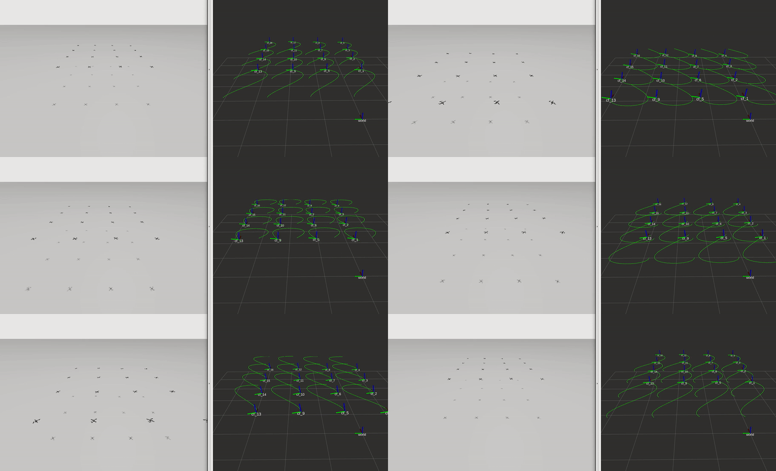
There are still a few open issues, including the absence of implemented decks for positioning, such as LPS and Lighthouse. Currently, the absolute position is sent from Gazebo to the SITL instance and fused in the estimator. Moreover, Gazebo requires quite a lot of computing power. We were able to run a maximum of four Crazyflies simultaneously on a relatively old laptop. However, a modern desktop CPU with multiple cores allows for simulating a significantly larger number of Crazyflies.

Multi-Agent Client

Independent of the simulation we designed a GUI for controlling and monitoring our multi-agent teams. It currently supports up to eight Crazyflies but could be upgraded for bigger teams in the future. So far it has been enough for our requirements.

Multi-Agent Client with six connected Crazyflies

A central feature is the interactive map, which makes up about half of the gui. This is a 2D representation of the flight area with a coordinate system drawn in. Connected Crazyflies are displayed as small circles on the map and a new target position can be assigned by clicking on the map after they have been selected by their corresponding button. If required, obstacles or paths to be flown can also be drawn into the map.

Pseudo-decentralized communication

An important aspect of a truly decentralized system is peer to peer communication. It allows information to be exchanged directly between agents and ideally takes place without a central entity. Currently peer to peer communication is not available in the Crazyflie ecosystem, but is in development.

For this reason, we have implemented a workaround in our client, enabling a pseudo-decentralized communication system. This involves adding an additional layer to the Crazy RealTime Protocol (CRTP), which we named the Multi-Agent Communication Protocol (MACP). It consists of an additional packet header made of the destination ID, source ID and a port as endpoint identifier. Every ID is unique and directly derived from the Crazyflie’s address.

These MACP packets are sent via the unused CRTP port 0x9. The packet routing mechanism implemented in the client forwards the packets to their destination. It is also possible to send packets as a broadcast or to address the client directly.

On the firmware side, we have added a corresponding interface to simplify the sending and receiving of macp packets. It is analogous to the CRTP implementation and allows the registration of callback functions or queues for incoming packets on corresponding ports. It can be activated via KBuild.

At least for use in the laboratory and the development of distributed algorithms, this method has proven its worth for us.

Project

We hope that the sim_cf2 simulation can also be useful to others. The complete source code is available on GitHub. Further information concerning installation and configuration can be found in the readme files in the respective repositories.

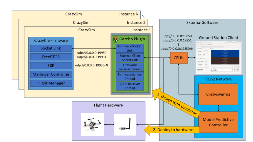
We would also like to point out that other simulations have been created that are based on sim_cf and therefore offer similar functionality. One of these projects is CrazySim, also available on GitHub. Moreover, there are ongoing efforts to officially integrate such a software-in-the-loop simulation into the Crazyflie firmware and ecosystem.

sim_cf2:

https://github.com/CrazyflieTHI/sim_cf2

Multi-Agent Client:

https://github.com/CrazyflieTHI/crazyflie-client-multi-agent-thi

Show-and-tell post of CrazySim:

https://github.com/orgs/bitcraze/discussions/995

For the original sim_cf Flight Simulator for the Crazyflie visit:

https://github.com/wuwushrek/sim_cf

A few years ago, we wrote a blogpost about the Commander framework, where we explained how the setpoint structure worked, which drives the controller of the Crazyflie, which is an essential part of the stabilization module. Basically, without these, there would not be any autonomy on the Crazyflie, let alone manual flight.

In the blogpost, we already shed some light on where different setpoints can come from in the commander framework, either from the Crazyflie python library (externally with the Crazyradio), the high level commander (onboard) or the App layer (onboard).

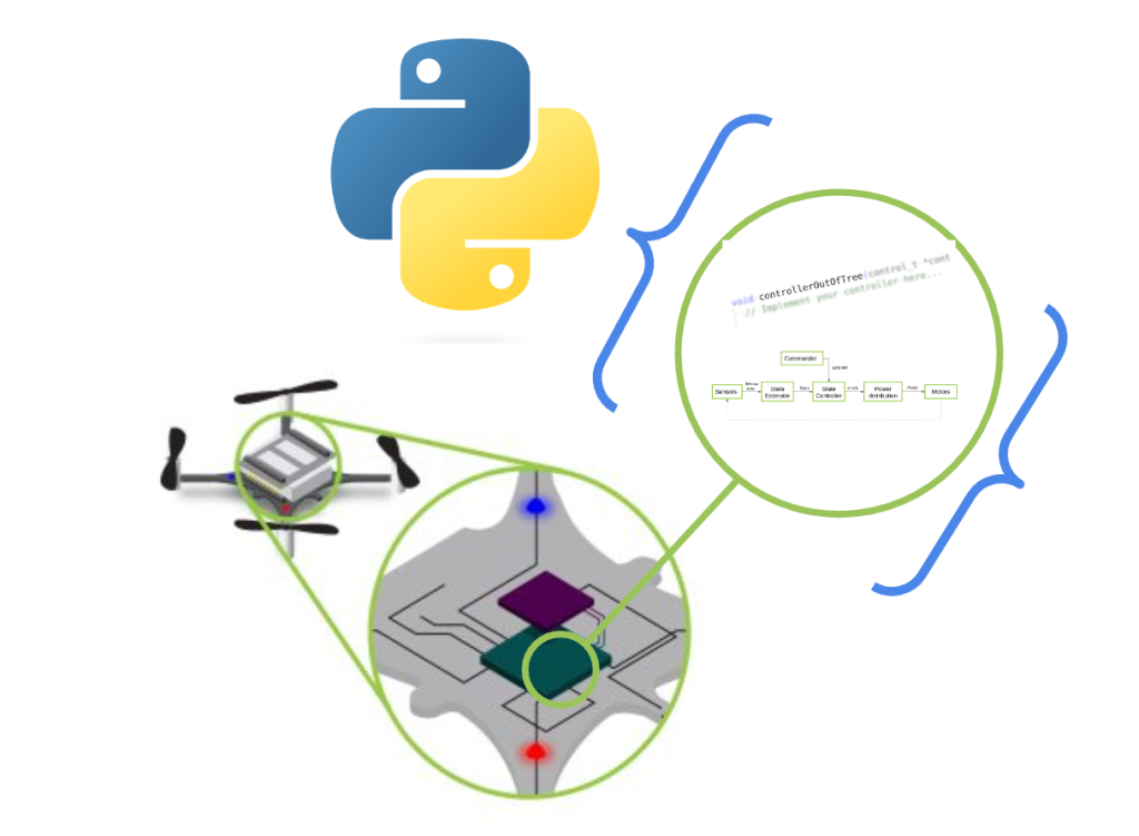
General framework of the stabilization structure of the crazyflie with setpoint handling. * This part is takes place on the computer through the CFlib for python, so there is also communication protocol in between. It is left out of this schematics for easier understanding.

However, we notice that there is sometimes confusion regarding these different functionalities and what exactly sends which setpoints and how. These details might not be crucial when using just one Crazyflie, but become more significant when managing multiple drones. Understanding how often your computer needs to send setpoints or not becomes crucial in such scenarios. Therefore, this blog post aims to provide a clearer explanation of this aspect.

Sending set-points directly from the CFlib

Let’s start at the lower level from the computer. It is possible to send various types of setpoints directly from a Python script using the Crazyflie Python library (cflib for short). This capability extends to tasks such as manual control:

send_setpoint(roll, pitch, yawrate, thrust)

or for hover control (velocity control):

send_hover_setpoint(vx, vy, yawrate, zdistance)

You can check the automatic generated API documentation for more setpoint sending options.

If you use these functions in a script, the principle is quite basic: the Crazyradio sends exactly 1 packet with this setpoint over the air to the Crazyflie, and it will act upon that. There are no secret threads opening in the background, and nothing magical happens on the Crazyflie either. However, the challenge here is that if your script doesn’t send an updated setpoint within a certain amount of time (default of 2 seconds), a timeout will occur, and the Crazyflie will drop out of the sky. Therefore, you need to send a setpoint at regular intervals, like in a for loop, to keep the Crazyflie flying. This is something you need to take care of in the script.

Example scripts in the CFlib that are sending setpoints directly:

Setpoint handling through Motion Commander Class

Another way to handle the regular sending of setpoints automatically in the CFLib is through the Motion Commander class. By initializing a Motion Commander object (usually using a context manager), a thread is started with takeoff that will continuously send (velocity) setpoints at a fixed rate. These setpoints can then be updated by the following functions, for instance, moving forward with blocking:

forward(distance)

or a giving body fixed velocity setpoint updates (that returns immediately):

start_linear_motion(vx, vy, vz, rate_yaw)

You can check the Motion Commander’s API-generated documentation for more functions that can be utilized. As there is a background thread consistently sending setpoints to the Crazyflie, no timeout will occur, and you only need to use one of these functions for the ‘behavior update’. This thread will be closed as soon as the Crazyflie lands again.

Here are example scripts in the CFlib that use the motion commander class:

Setpoint handling through the high level commander

Prior to this, all logical and setpoint handling occurred on the PC side. Whether sending setpoints directly or using the Motion Commander class, there was a continuous stream of setpoint packets sent through the air for every movement the Crazyflie made. However, what if the Crazyflie misses one of these packets? Or how does this stream handle communication with many Crazyflies, especially in swarms where bandwidth becomes a critical factor?

This challenge led the developers at the Crazyswarm project (now Crazyswarm2) to implement more planning autonomy directly on the Crazyflie itself, in the form of the high-level commander. With the High-Level Commander, you can simply send one higher-level command to the Crazyflie, and the intermediate substeps (setpoints) are generated on the Crazyflie itself. This can be achieved with a regular takeoff:

take_off(height)

or go to a certain position in space:

go_to(x, y)

This can be accomplished using either the PositionHLCommander, which can be used as a context manager similar to the Motion Commander (without the Python threading), or by directly employing the functions of the High-Level Commander. You can refer to the automated API documentation for the available functions of the PositionHLCommander class or the High-Level Commander class.

Here are examples in the CFlib using either of these classes:

Notes on location of autonomy and discrepancies

Considering the various options available in the Crazyflie Python library, it’s essential to realize that these setpoint-setting choices, whether direct or through the High-Level Commander, can also be configured through the app layer onboard the Crazyflie itself. You can find examples of these app layer configurations in the Crazyflie firmware repository.

It’s important to note some discrepancies regarding the Motion Commander class, which was designed with the Flow Deck (relative positioning) in mind. Consequently, it lacks a ‘go to this position’ equivalent. For such tasks, you may need to use the lower-level send_position_setpoint() function of the regular Commander class (see this ticket.) The same applies to the High-Level Commander, which was primarily designed for absolute positioning systems and lacks a ‘go forward with x m/s‘ equivalent. Currently, there isn’t a possibility to achieve these functionalities at a lower level from the Crazyflie Python library as this functionality needs to be implemented in the Crazyflie firmware first (see this ticket). It would be beneficial to align these functionalities on both the CFlib and High-Level Commander sides at some point in the future.

Hope this helps a bit to explain the commander frame work in more detail and where the real autonomy lies of the Crazyflie when you use different commander classes. If you have any questions on what the Crazyflie can do with these, we advise you to ask your questions on discussions.bitcraze.io and we will try to point you in the right direction and give examples!

It’s not often a blog post happens on the 25th of December, so this time, you’re having a treat with some new Bitcraze prototypes as a present from us! If you have time to get away from the Christmas table, there’s something we’d love you to watch:

Now let’s try to see if you noticed all the new stuff you see in this video!

Our new flight lab

We teased it, but in the beginning of December, we got our extended flight lab! We added 110 m2 to our flight space. It was a rush to have everything ready for the video – we cleaned everything, painted the walls and the green logo, set up the positioning system without our truss… But now we’re happy to show you how big the space is! Even if it’s hard to convey the real size on camera.

The Crazyflie 2.1 brushless

We already talked about it in this blog post, but the brushless has made significant progress and we feel confident that you will get your hands on it in 2024. Here, we use the extra power for a fast and agile flight. It also was very stable and didn’t crash once during the shooting!

The Lighthouse V2

Yes, you counted right! The Brushless flew with 16 base stations! We’ve worked really hard this past three months to create a new Lighthouse deck – the Lighthouse deck 2.0. It could get its position from 16 base stations. That’s 4 times more than what was previously possible! It behaved consistently well during the different tries, and we are really happy with the result. Right now, it’s just a prototype, but we’re hoping to get it to the next step in the coming months.

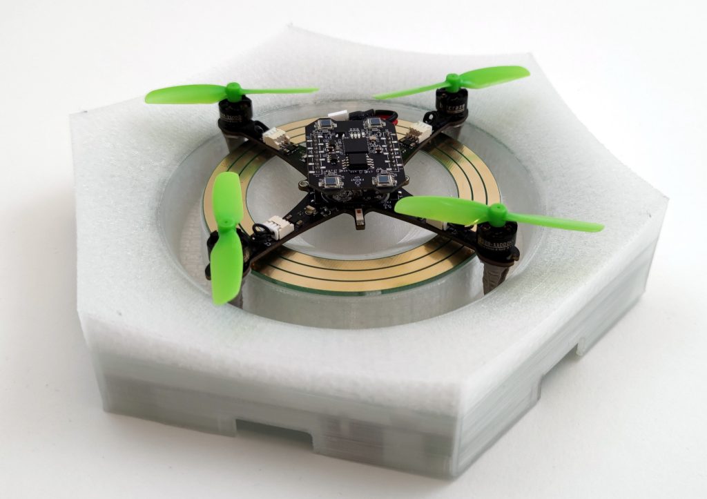
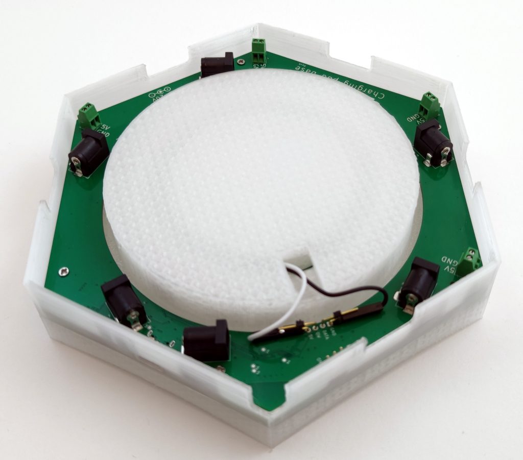
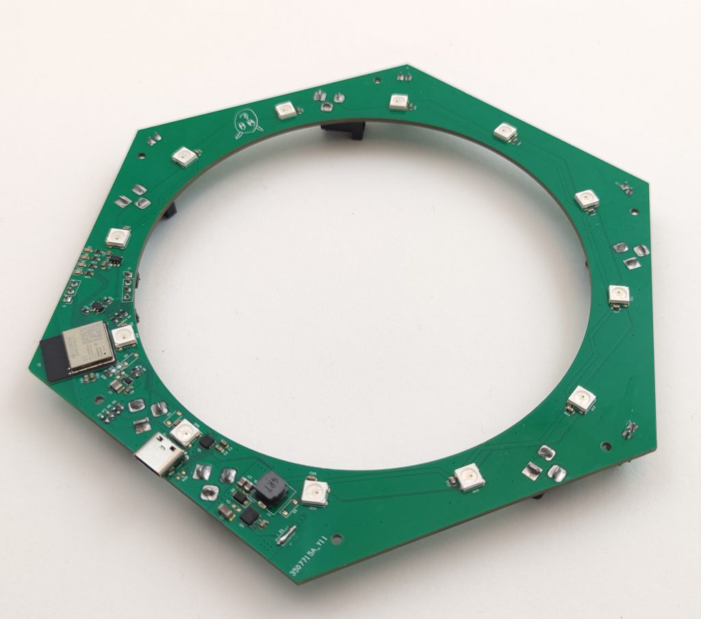
The contact charging station

Marcus created a power charger for the Brushless that doesn’t need any extra deck to allow for charging. It connects with the brushless feet. It has also the cool feature of changing LEDs indicating the status (idle, charging or charged). It is also a prototype, and we don’t know if this will end up being a product

The high-power LED

This is trickier to see, but it’s not our usual LED ring that the brushless carries. It’s a new, powerful LED underneath. It is so powerful that it nearly blinded us when we tried it for the first time. We put a diffuser on it, and it allowed the Crazyflie to be visible at such a high pace! This is a prototype too of course and we’re not sure if we will release it, but it’s fun to use for this kind of project.

Other announcements

During this week, our office is closed- we take this week to celebrate and rest a little before 2024. This means that shipping and support will be greatly reduced.

But we’re back the week after- at a somewhat reduced pace though. The developer meeting on the 3rd of January is maintained but without any presentation. We’ll take this time to answer any questions you have and talk a little! The details are here.

Bitcraze got their presents this year: a handful of working prototypes! We hope we got your wishes too, merry Christmas to you!

Before we start settling down and preparing for Christmas, it’s time for another release! The last one was before the summer in July, and we’ve had quite a few changes on the development master branch that we’d like to share. You can now download the latest Cfclient through pip and install the newest firmware on the Crazyflie to 2023.11 via the CFclient.

Latest changes in CFclient and Cflib

The most significant change in the CFclient is that we have finally transitioned from QT5 to QT6 for the GUI graphics. Additionally, we have addressed some issues with the toolboxes. Finally, we have added an information box to indicate the state of the supervisor, such as whether the Crazyflie is considered tumbled, flying, or if a restart is required because it is locked.

Cfclient when the crazyflie is tumbled with supervisor info

For the backend, namely the Crazyflie Python library, some important changes have been implemented. Along with fixes to the parameter and logging framework, full-state setpoints have been introduced. This feature has existed in firmware for a while due to the Crazyswarm1 project (now Crazyswarm2), but it wasn’t implemented in the cflib until now. Additionally, it’s now necessary to use `notify_setpoint_stop` in cases of switching between high-level setpoints and regular position setpoints. There is also a generic motion capture example now based on the libmotioncapture library.

Note that even though the CFclient has been converted to QT6, there are several examples in the Cflib folder that have not been updated yet. This will be fixed soon, and a ticket has been created for it. Additionally, in the Bitcraze-VM, there have been some reported issues with QT6 (see this ticket).

Latest changes in the firmware

The firmware has undergone some important changes too. On the STM side of things, the hybrid TDOA mode has been merged (check out this recent blog post). This feature is still considered experimental, so please refer to the documentation for the right settings. Additionally, support for the supervisor information box in the CFclient has been added. To utilize it, both the firmware and CFclient need to be updated. There is also a new example demonstrating communication between gap8 and cpx. Last but not least, it is now possible to create Python bindings for portions of the Kalman filter, mainly for the Loco positioning system. On the other hand, the NRF firmware has no added functionalities except for some build changes and fixes.

Crazyradio2 + LPS tools

We’ve also made some improvements in other firmware or tools. Starting with the Crazyradio2, which includes fixes for broadcasting (important for you Crazyswarm2 folks!). We also aimed to make a new release of LPS tools since we heard that people were experiencing issues with USB devices. Unfortunately, there are some problems with the GitHub release actions, so that will likely be delayed. For anyone facing USB issues, you can install the LPS tools from source with Python following the ReadMe’s instructions.

Release details and Remaining issues

So here are the details of all that is released:

Some things still require attention that are a bit affected by this release, but we haven’t had the time to fix it yet:

  • Fix issues with LPS tools and release (see this ticket)
  • CFclient seems to be broken on the bitcraze-VM (see this ticket)
  • CFlib examples with QT-based GUI are still on QT5 (see this ticket)
  • The newest CFclient seems to need additional packages in some cases ( see this and this ticket)

Please let us know at https://discussions.bitcraze.io if you are having more problems.

Developer meeting this Wednesday

As we already announced last week in the Monday blog post, we will be having a developer meeting this Wednesday (6th Dec, 3 pm CET) regarding the Flow deck (refer to this discussion thread for joining information). Since we usually don’t fill up the entire hour, the last part of the developer meeting is available for some generic support questions face-to-face (online), including questions about the release!

The Flow deck has been around for some time already, officially released in 2017 (see this blog post), and the Flow deck v2 was released in 2018 with an improved range sensor. Compared to MoCap positioning and the Loco Positioning System (based on Ultrawideband) that were already possible before, optical flow-based positioning for the Crazyflie opened up many more possibilities. Flight was no longer confined to lab environments with set-up external systems; people could bring the Crazyflie home and do their hacking there. Moreover, doing research for exploration techniques that cannot rely on external positioning systems was possible with it as well. For example, back in my day as a PhD student, I relied heavily on the Flow deck for multi-Crazyflie autonomous exploration. This would have been very difficult without it.

However, despite the numerous benefits that the Flow deck provides, there are also several limitations. These limitations may not be immediately familiar to many before purchasing a Crazyflie with a Flow deck. A while ago, we wrote a blog post about positioning systems in general and even delved into the Loco Positioning System in detail. In this blog post, we will explore the theory of how the Flow deck enables the Crazyflie to fly, share general tips and tricks for ensuring stable flight, and highlight what to avoid. Moreover, we aim to make the Flow deck the focus of next week’s Developer meeting, with the goal of improving or clarifying its performance further.

Theory of the Flow deck

I won’t delve into too much detail but will provide a generic indication of how the Flow deck works. As previously explained in the positioning system blog post, the Flow deck is a relative positioning system with onboard estimation. “Relative” means that wherever you start is the (0, 0, 0) position. The extended Kalman filter processes flow and height information to determine velocity, which is then integrated to estimate the position—essentially dead reckoning. The onboard Kalman filter manages this process, enabling the Crazyflie to use the information for stable hovering.

Image from Positioning System Overview blogpost

The optical flow sensor (PMW3901) calculates pixel flow per frame (this old blog post explains it well), and the IR range sensor (VL53L1x) measures height up to 4 meters (under ideal conditions). The Kalman filter incorporates a measurement model that describes the relationship between these two values and the velocity of the Crazyflie. More detailed information can be found in the state estimation documentation. This capability allows the Crazyflie to hover, as explained in the getting started tutorial.

Image from state estimation repo documentation

Tips & Tricks and Limitations

If you want to fly with the Crazyflie and the Flow deck, there are a couple of things to take in mind:

  • Take off from a floor with texture. Natural texture like wood flooring is probably the best.
  • The floor shouldn’t be too shiny, and be aware of infrared scattering for the height sensor
  • The room should be well-lit, as the sensor needs to see the texture.

There are certain situations that the Flow deck has some issues with:

  • Low or no texture. Flying above something that is only one plain color
  • Black areas. Similar reason to flying above no texture, but it’s more difficult than usual. Especially with startup, the position estimate diverges
  • Low light conditions
  • Flying over its own shadow

We made a video that shows these types of behaviors, starting of course with the most ideal flying conditions:

Moreover, it is also important to note that you shouldn’t fly too high or yaw too often. The latter will make the Crazyflie drift, as the optical flow cannot be distinguished as being caused by the yaw movement.

Developer meeting about Flow deck

We believe that many of the issues people experience are primarily due to the invisibility of the positioning quality. In many of our examples, the Crazyflie will not take off if the position is stable. However, we don’t have a corresponding functionality in our CFclient, as it is more up to the user to recognize when the positioning is diverging. There is a lot of room for improvement in this regard.

This is the reason why the next developer meeting will specifically focus on the Flow deck, which will be on Wednesday the 6th of December, 3 pm central European time. During the meeting, we will explain more about the Flow deck, discuss the issues we are facing, and explore ways to enhance the visibility of positioning quality. Check out this discussion thread for information on how to join.

It seems that many of you are very interested in simulation. We might have gotten the hint when we noticed that our July’s development meeting had our best attendance so far! Therefore, we will be planning a new developer meeting to discuss the upcoming plans for supporting simulation for the Crazyflie.

Getting Started with Simulation tutorial

Perhaps you are not aware, but there is actually a Getting Started tutorial for simulation that has been available for a little over 2 months now. Unfortunately, circumstances prevented us from writing a blog post about it, but we’ve noticed that not all of you are aware of it yet!

The getting-started tutorial demonstrates how to set up the Webots simulator, which already includes Crazyflie models and some cool examples:

  • An example that you can control the Crazyflie with the keyboard
  • An example that the Crazyflie does wall following autonomously

The latter is based on the example app layer for wall-following in the crazyflie-firmware repository. Starting this year, there’s also a Python library equivalent available.

The tutorial concludes with instructions on how to edit these controllers. Alternatively, you can choose to run the files directly from the crazyflie-simulation repository. After completing the tutorial, you can explore the simulation repository documentation for more information and to access additional examples.

Upcoming plans

With so many plans and so little time! This is a common phrase at Bitcraze, and it’s a symptom of being an overly ambitious, but too small, team. By the way, we are still looking for more people :). Nonetheless, we have big plans to take our Crazyflie simulation to the next level:

  • ROS 2 Crazyflie model for Webots: The Crazyflie has been a part of the Webots standard robots for 2 years now, but we still need to implement the Crazyflie into the Webots ROS 2 repository.
  • Better (new) Gazebo support: Currently, we only have a very simple example for Gazebo, which is limited to motors with no control input. Working with the C++ API can be a bit challenging, so it might be worth considering the use of ROS 2 in the loop here. Let’s see what comes out of it.
  • Integration into Crazyswarm2: Once the Webots ROS2 node has been released, integrating the Crazyflie simulation into Crazyswarm2 will become more straightforward.
  • Improvement to the Python bindings: We’ve had Python bindings for controllers and the high-level commander for a while. Recently, we also added Python bindings for the estimator (currently for loco positioning only). However, there are still some issues to address with the Python bindings for the controllers due to timing issues with the simulators.
  • Linking with our CFLIB: Currently, both Webots and the Crazyflie Python library use entirely different APIs. This means that these scripts are not compatible and you’ll need to be creative not to reuse new code. However, wouldn’t it be nice to use a python example from the python library with a --sim and that it would actually control the Crazyflie in the simulator instead?

Of course, there are probably more improvements that we haven’t thought of yet, but that’s why we have developer meetings!

Come and join us at the Developer meeting.

We will be hosting another developer meeting on November 1st at 15:00 Central European Time (accounting for the time-shift from summer to autumn). You can find details on how to join in the discussion thread here.

Just for your information, I (Kimberly) am the main driving force behind our simulation efforts. However, I’m currently on partial sick leave and will soon be on full leave for a while. I kindly ask for your patience with the pace of ongoing developments. Remember, it’s an open-source project, so if you’d like to contribute and help out, we would greatly appreciate it :)

We talked about it before the summer, and it’s finally here! The 350 mAh battery is now available in our shop. It implies some changes in the products we offer, so here is a breakdown of what’s new:

The 350 mAh battery

It’s here!

It is more powerful than the 250 mAh battery that comes with your Crazyflie. We based it on the Tattu 350mAh 3.7V 30C 1S1P but with some custom works like gold connectors, tailored wire length, and awesome Bitcraze graphics on it. On top of the added power, the upgrade has higher capabilities, (30C burst current, which is more than 10 Amp) and higher energy density (~130 Wh/kg instead of ~105 Wh/kg). It all means that this could boost your hover time up to 10 minutes, and you’ll have more punch during acceleration! It is, though, more expansive than the 250 mAh.

The pin headers

The 350 mAh is thicker than the stock battery, which means you would need longer pin headers in order to snug it onto your Crazyflie. For that, there are now 9mm pin headers available in the shop. This means that now, you can get 3 different male connectors:

  • the 8+14mm is the one that comes with your Crazyflie kit. It’s meant to be phased out at some point. It allows to fit 1 or 2 decks and the 250 mAh battery.
  • the 9+15mm is slightly longer and is available in the shop – both as a spare part and in the upgraded battery bundle. It allows to fit 1 or 2 decks and the 350 mAh battery.
  • the male long connector: the longest pin of all, it’s the one that allows you to fit 3 decks.

Since it makes more sense to have slightly longer pins, the male connectors as spare parts are now slightly longer ones than those you get in your Crazyflie kit.

If you’re not sure, you can always buy the upgraded battery bundle that offers the 350 mAh battery with the right pin headers.

Bundles

The 350 mAh battery is much more suited for swarms than the 250 mAh, that’s why we’re planning on having an upgraded offer for our swarm bundles. In the coming week, both the Lighthouse and the Loco Swarms will be fitted for the updated offer. That would mean that it will include the new batteries with the right pin headers as well – there will be a slight price increase to match the price of the batteries.

Bare PCB

But that’s not the only surprise waiting for you in the shop: you can now also buy a spare Crazyflie PCB! We thought it would be good to have this option in the store – in case you have crashed too many times and you only just need the PCB!

Right now, it may seem a little confusing, between our different propellers, batteries, or pin headers. It’s mainly because we are trying to, slowly, build up a better, upgraded offer – which will, eventually, culminate in an upgraded Crazyflie 2.1, where the 47-17 propellers and the 9mm pin headers are standards. We’re also planning to publish a guide to help you quickly figure out what would best suit your needs!

Today, Suryansh Sharma from TU Delft presents the open-source Gimbal they devised. Enjoy!

Crazyflies (and other drones in this weight class) are extremely fun to fly and prototype with! But if you are also a scientist or tinkerer and not a well-skilled drone pilot then you might struggle with flying these platforms especially when testing new control loops or experimental code. While crashing also teaches a lot about the behavior of the system, sometimes we are interested in seeing the system dynamics without breaking the drone.

Currently, doing this for such small drones is not easy. We need something lightweight and still accessible. To solve this, we made Open Gimbal: a specially designed 3 degrees of freedom (DoF) platform that caters to the unique requirements of these tiny drones. We make two versions, (a) Tripod version which can be mounted on a camera / light tripod with a screw thread of sizes 1/4-20 UNC or 3/8-16 UNC (b) Desktop version which can be placed on a table top.

Our approach focuses on simplicity and accessibility. We developed an open-source, 3-D printable electro-mechanical design that has minimal size and low complexity. This design facilitates easy replication and customization, making it widely accessible to researchers and developers. The platform allows for unrestricted and free rotational motion, enabling comprehensive experimentation and evaluation. You can see the movement from the CAD version below:

Degrees of Rotational freedom that Open Gimbal provides

You can also check out the interactive CAD model and see how the gimbal moves here. All of the 3D model files as well as the BOM and instructions for assembly can be found in our repository here.

In our publication, we also address the challenges of sensing flight dynamics at a small scale. To do so, we have devised an integrated wireless batteryless sensor subsystem. Our innovative solution eliminates the need for complex wiring and instead uses wireless power transfer for sensor data reception. You can read all about how we do this in our paper here.

If you do end up using the platform for research then you can cite us using the details below:

@ARTICLE{10225720, author={Sharma, Suryansh and Dijkstra, Tristan and Prasad, Ranga Venkatesha}, journal={IEEE Sensors Letters}, title={Open Gimbal: A 3 Degrees of Freedom Open Source Sensing and Testing Platform for Nano- and Micro-UAVs}, year={2023}, volume={7}, number={9}, pages={1-4}, doi={10.1109/LSENS.2023.3307121}}

I hope that you find the Open Gimbal useful! Feel free to reach out to me at Suryansh.Sharma@tudelft.nl if you have any ideas/questions or if you end up making an Open Gimbal yourself!

After a nice (but rainy) summer, everyone is back at the office and we’re coming back to business as usual at Bitcraze. This blog post is dedicated to various bits of news, in order to get you caught up on what’s been happening during the summer.

Dev meeting theme

There were no dev meetings in August to allow everyone to rest and enjoy their vacations, but after this hiatus, we’re back in the saddle! The dev meeting will happen, as usual, on the first Wednesday of the month, so the 6th of September, at 15.00 CEST.

This month, Arnaud is going to talk about the lib: what is its current status, its architecture, and some hopes we have for the future. As usual, we’ll have a short presentation, and then a discussion; you can also join if you have more general questions or feedback. If you’re interested and willing to take part in this discussion, you can check the information on Github: https://github.com/orgs/bitcraze/discussions/884

Chargers out of stock

Some items were out of stock during the summer (like the HQ propellers) that we thankfully received soon after we came back. Unfortunately, one product is still not available: the battery charger. Since it’s part of the Swarm bundles, it also means that the bundles are out of stock too. But the wait for their restocking shouldn’t be too long, as they are scheduled to arrive around the end of next week. We’re hoping it’s not a big inconvenience for you and we thank you for your patience!

Problems with payment

We’ve noticed that some of you had some problems getting their payment through in our shop. If you’re one of the unlucky ones who faced this issue, we apologize for the inconvenience, and we want you to know we’re working with our payment provider to figure out a solution. This, unfortunately, can take some time because of the number of parties involved (there’s us, the payment provider, different banks, so the situation gets quite complex quickly). In the meantime, if you should encounter such a problem, don’t hesitate to send us an email at contact@bitcraze.se and we can help out. It would also help us to know who is facing this issue.